Category The Enigma of. the Aerofoil

Introduction: The Question to Be Answered

’Tis evident, that all the sciences have a relation, greater or less, to human nature; and that however wide any of them may seem to run from it, they still return back by one passage or another.

david hume, A Treatise of Human Nature (1739-40)1

Why do aircraft fly? How do the wings support the weight of the machine and its occupants? Even the most jaded passengers in the overcrowded airliners of the present day may experience some moments of wonder—or doubt—as the machine that is to transport them lifts itself off the runway. Because the action of the air on the wing cannot be seen, it is not easy to form an idea of what is happening. Some physical processes are at work that must generate powerful forces, but the nature of these processes, and the laws they obey, are not open to casual inspection. If the passengers looking out of the window really want an explanation of how a wing works, they must do what any lay person has to do and ask the experts. Unfortunately the answers that the ex­perts will give are likely to be highly technical. It will take patience by both parties if communication is not to break down. But given goodwill on both sides, the experts should be able to find some simplified formulations that will be useful to the nonexperts, and the nonexperts should be able to deepen their grasp of the problem.

In this book I discuss the question of why airplanes fly, but I approach the problem in a slightly unusual way. I describe the history behind the technical answer to the question about the cause of “lift,” that is, the lifting force on the wing. I analyze the path by which the experts, after much disagreement, ar­rived at the account they would now give. I am therefore not simply asserting that airplanes fly for this or that reason; I am asserting that they were under­stood to fly for this or that reason. I am interested in the fact that different and rival understandings were developed by different persons and in different places. I cannot speak as a professional in the field of aerodynamics; nor is my position exactly that of a layperson. I speak as a historian and sociologist of science who is poised between these categories.2

What are the specific questions that I am addressing and to which I hope to offer convincing answers? To identify them I first need to give some back­ground. The practical problem of building machines that can be flown, that is, the problem of “mechanical” or “artificial” flight, was solved in the final years of the nineteenth century and the early years of the twentieth century. In the 1890s Otto Lilienthal in Germany successfully built and flew what we today would call hang gliders. From 1903 to 1905 the Wright brothers in the United States showed that sustained and controlled powered flight was pos­sible and practical. What had long been called the “secret” of flight was now no longer a secret. But not all of the secret was revealed. Some parts of it remained hidden, and indeed, some parts are still hidden today. The practi­cal successes of the pioneer aviators still left unanswered the question of how a wing generated the lift forces that were necessary for flight. The pioneers mostly worked by trial and error. Some had experimented with models and taken measurements of lift and drag (the air resistance opposing the motion), but the measurements were sparse and unreliable.3 No deeper theoretical un­derstanding had prompted or significantly informed the early successes of the pioneers, nor had theory kept pace with the growth of practical under­standing. The action of the air on the wing remained an enigma.

A division of labor quickly established itself. Practical constructors con­tinued with their trial-and-error methods, while scientists and engineers be­gan to study the nature of the airflow and the relation between the flow and the forces that it would generate. For this purpose the scientists and engineers did not just perform experiments and build the requisite pieces of apparatus, such as wind channels. They also exploited the resources of a branch of ap­plied mathematics that was usually called hydrodynamics. The name “hydro­dynamics” makes it sound as if the theory was confined to the flow of water, but in reality it was a mathematical description that, with varying degrees of approximation, was applied to “fluids” in general, including air. Thus was born the new science of aerodynamics. The birth was accompanied by much travail. One problem was that the mathematical theory of fluid flow was im­mensely difficult. The need to work with this theory effectively excluded the participation of all but the most mathematically sophisticated persons, and this did not go down well with the practical constructors. The mathematical analysis also depended for its starting point on a range of assumptions and hypotheses, about both the nature of the air and the more or less invisible pattern of the flow of air over, under, and around the wing. Only when the flow was known and specified could the forces on the wing be calculated. Assumptions had to be made. The unavoidable need to base their investiga­tions on a set of assumptions proved to be deeply divisive. Different groups of experts adopted different assumptions and, for reasons I explain, stuck to them.

The first part of this historical story, the practical achievement of con­trolled flight, has been extensively discussed by historians. Pioneers, such as the Wright brothers, have been well served, and the attention given to them is both proper and understandable.4 The second part of the history, the de­velopment of the science of aerodynamics, is somewhat less developed as a historical theme, though a number of outstanding works have been written and published on the subject in recent years.5 The present book is a contribu­tion to this developing field in the history of science and technology.

In the early years of aviation there were two, rival theories that were in­tended to explain the origin and nature of the lift of a wing. They may be called, respectively, the discontinuity theory and the circulatory (or vortex) theory. The names derive from the particular character of the postulated flow of air around the wing. (I should mention that the circulatory theory is, in effect, the one that is accepted today.) My aim is to give a detailed account of how the advocates of the two theories developed their ideas and how they oriented themselves to, and engaged with, the empirical facts about flight. To do this I found that I also needed to understand how they oriented them­selves to, and engaged with, one another. I show that these two dimensions cannot be kept separate. This is why I have prefaced the work with the quo­tation from the famous Edinburgh historian and sociologist David Hume. The more one studies the technical details of the scientific work, the more evident it becomes that the social dimension of the activity is deeply impli­cated in these details. The more closely one analyses the technical reasoning, the more evident it becomes that the force of reason is a social force. The historical story that I have to tell about the emerging understanding of lift is, therefore, at one and the same time both a scientific and a sociological story. To understand the course taken by the science it is necessary to understand the role played by the social context, and to appreciate the role played by the social context it is necessary to deconstruct the technical and mathematical arguments.

In principle none of this should occasion surprise. Scientists and engi­neers do not operate as independent agents but as members of a group. They cannot achieve their status as scientists and engineers without being educated, and education is the transmission of a body of culture through the exercise of authority. Education is socialization.6 Scientists and engineers see them­selves as contributing to a certain discipline, as being members of certain institutions, as having loyalties to this laboratory or that tradition, as being students of A or rivals of B. Their activities would be impossible unless behav­ior were coordinated and concerted. For this the individuals concerned must be responsive to one another and in constant interaction. Their knowledge is necessarily shared knowledge, though, in its overall effects, the process of sharing can be divisive as well as unifying. The sharing is always what Hume would call a “confined” sharing.

All too frequently, when scientific and technical achievements become objects of commentary, analysis, or celebration, these simple truths are ob­scured. Academic culture is saturated with individualistic prejudices, which encourage us to trivialize the implications of the truth that science is a col­lective enterprise and that knowledge is a collective accomplishment. Phi­losophers of science actively encourage historians to distinguish between, on the one side, “cognitive,” “epistemic,” or “rational” factors and, on the other side, “social” factors. They enjoin the sociologist to “disentangle” scientific reasoning from “social influences” and to distinguish what is truly “internal” to science from what is truly “external.”7 These recommendations are treated as if they were preconditions of mental hygiene and based on self-evident truths. Historians and sociologists of science know better. They know that the problem of cognitive order is the problem of social order.8 These are not two things, even two things that are closely connected; they are one thing described from different points of view. The division of a historical narrative into “the cognitive” and “the social,” or “the rational” and “the social,” is wholly artificial. It is methodologically lazy and epistemologically naive.

I shall now briefly sketch the overall structure of the events I describe in this volume. Of the two theories of lift that I mentioned, one of them, the dis­continuity theory, was mainly developed in Britain. It was based on work by the eminent mathematical physicist Lord Rayleigh. The other, the circulatory theory, was mainly developed in Germany. It is associated primarily with the German engineer Ludwig Prandtl, although it had originally been proposed by the English engineer Frederick Lanchester. It rapidly became clear that the discontinuity theory was badly flawed because it only predicted about half of the observed amount of lift. At this point, shortly before the outbreak of World War I (or what the British call the Great War) in 1914, the British awareness of failure might have reasonably led them to turn their attention to the other theory, the theory of circulation. They did not do this. They knew about the theory but they dismissed it. At Cambridge, G. I. Taylor, for example, treated the discontinuity theory as a mathematical curiosity, but he also found Lanchester’s theory of circulation equally unacceptable. The reasons he gave to support this judgment were important and widely shared. Meanwhile the Germans embraced the idea of circulation and developed it in mathematical detail. The British also knew of this German reaction but still did not take the theory of circulation seriously. It was not until after the war ended in 1918 that the British began to take note. They found that the Germans had developed a mathematically expressed, empirically supported, and practically useful account of lift. Even then the British had serious res­ervations. The negative response had nothing to do with mere anti-German feeling. The British scientific experts were patriots, but, unlike some in the world of aviation, they were not bigots. Why then were they so reluctant to take the theory of circulation seriously? This is the main question addressed in the book.9

There are already candidate answers to this question in the literature, but they are answers of a different kind to the one I offer. The neglect of Lan – chester’s work became something of a scandal in the 1920s and 1930s, so it was natural that explanations and justifications were manufactured to account for it. Sir Richard Glazebrook, the head of the National Physical Laboratory, played an important role in British aviation during these years and was the source of one of the standard excuses, namely, that Lanchester did not pres­ent his ideas with sufficient mathematical clarity. Well into the midcentury, British experts in aerodynamics, who, along with Glazebrook, shared respon­sibility for the neglect of Lanchester’s ideas, were scratching their heads and wondering how they could have allowed themselves to get into this position. Clarity or no clarity, they had turned their backs on the right theory of lift and had become bogged down with the wrong one.

The retrospective accounts and excuses that have been given have been both fragmentary and feeble, though Lanchester’s biographer, P. W. Kings – ford, writing in 1960, still went along with a version of Glazebrook’s excuse.10 Other existing accounts merely tend to embellish the basic excuse by invok­ing the personal idiosyncrasies of the leading actors. The problem is ana­lyzed as a clash of personalities. It is true that some of those involved had strong characters as well as powerful intellects, and some of them could pass as colorful personalities. All this will become apparent in what follows. The psychology of those involved is clearly an integral part of the historical story, but such accounts miss the very thing that I want to emphasize and that I believe is essential for a proper analysis, namely, the interconnection of the sociological and technical dimensions. Only an account that is technically informed, and sensitive to the social processes built into the technical content of the aerodynamic work, will make sense of the history. I want to show that the real reasons for the resistance to the vortex or circulatory theory of lift were deep and interesting, but not really embarrassing at all.

Although I have posed the question of why the British resisted the the­ory of circulation, I do not believe it can be answered in isolation from the question of why the Germans embraced it. Both reactions should be seen as equally problematic. The historical record shows that the same type of causes were at work in both British and German aerodynamics. In both cases the ac­tors drew on the resources of their local culture and elaborated them in ways that were typical of their milieu and were encouraged by the institutions of which they were active members. Of course, the cultures and the institutions were subtly different. My explanation of the German behavior is thus of the same kind as my explanation of the British. The same variables are involved, but the variables have different values. Seen in this way the explanation pos­sesses a methodological characteristic that has been dubbed “symmetry.” Be­cause the point continues to be misunderstood, I should perhaps emphasize the words “same kind.” I am not saying that the very same causes were at work but that the same kinds of cause were in operation. Symmetry, in this sense, is now widely (though not universally) accepted as a methodologi­cal virtue in much historical and sociological work. Conversely, it is widely rejected as an error, or treated as a triviality, by philosophers. I hope that see­ing the symmetry principle in operation will help convey its meaning more effectively than merely trying to capture it in verbal formulas or justify it by abstract argument.

The overall plan of the book is as follows. In chapter 1 I start my account of the early British work in aerodynamics with the foundation of the con­troversial Advisory Committee for Aeronautics in 1909. The committee was presided over by Rayleigh. The frontispiece, taken from the Daily Graphic of May 13, 1909, shows some of the leading members of the committee striding purposefully into the War Office for their first meeting, and then emerging afterward looking somewhat more relaxed. The minutes of that important meeting are in the Public Record Office and reveal what they talked about in the interval between those two pictures.11 It is a matter of central concern throughout this book. Chapter 2 lays the foundation for understanding the two competing theories of lift by sketching the basic ideas of hydrodynam­ics and the idealized, mathematical apparatus that was used to describe the flow of air. A nontechnical summary is provided at the end of the chapter. In chapter 3, I introduce the discontinuity theory of lift and describe the British research program on lift and the frustrations that were encountered. Chap­ter 4 is devoted to the circulatory or vortex theory and describes the hostile reception accorded to Lanchester among British experts. I pay particular at­tention to the reasons that were advanced to justify the rejection. In chapter 5, I identify and contrast two different intellectual traditions that were brought to bear on the theory of lift. One of them was grounded in the mathematical physics cultivated in Britain and preeminently represented by the graduates of the Cambridge Mathematical Tripos. The other tradition, called technische Mechanik, or “technical mechanics,” was developed in the German technical colleges and was integral to Prandtl’s work on wing theory. Chapters 6 and 7 provide an account of the German development and extension of the circu­lation theory as worked out in Munich, Gottingen, Berlin, and Aachen. In chapters 8 and 9 there is a description of the British postwar response, which took the form of a period of intense experimentation; it also gave rise to some remarkable and revealing theoretical confrontations. What, exactly, did the experiments prove? The British did not find it easy to agree on the answer.

The divergence between British and German approaches was effectively ended in 1926 with the publication, by Cambridge University Press, of a text­book that became a classic statement of the circulation theory. The book was Hermann Glauert’s The Elements of Aerofoil and Airscrew Theory.12 Glauert, an Englishman of German extraction, was a brilliant Cambridge mathemati­cian who, in the 1920s, broke ranks and became a determined advocate of the circulation theory. As the title of Glauert’s book indicates, he did not just work on the theory of the aircraft wing, but he also addressed the theory of the propeller. This is a natural generalization. The cross section of a propel­ler has the form of an aerofoil, and a propeller can be thought of as a rapidly rotating wing. The “lift” of this “wing” becomes the thrust of the propeller, which overcomes the air resistance, or “drag,” as the aircraft moves through the air. Glauert’s book also dealt with the theory of the flow of air in the wind channel itself, that is, the device used to test both wings and propellers. This aspect of the overall theory was needed to ensure that aerodynamic experi­ments and tests were correctly interpreted. As always in science, experiments are made to test theories, but theories are needed to understand the experi – ments.13 The discussions of propellers and wind channels in Glauert’s book are important and deserve further historical study, but, on grounds of prac­ticality, I set aside both the aerodynamics of the propeller and the methodol­ogy of wind-channel tests in order to concentrate exclusively on the story of the wing itself.14

In the final chapter, chapter 10, I survey the course of the argument and consider objections to my analysis, particularly those that are bound to arise from its sociological character. I use the case study to challenge some of the negative and inaccurate stereotypes that still surround the sociology of scien­tific and technological knowledge. I also ask what lessons can be drawn from this episode in the history of aerodynamics. Does it carry a pessimistic mes­sage about British academic traditions and elitism? What does it tell us about the difference between Gottingen and Cambridge or between engineers and physicists? Finally, I ask what light the history of aerodynamics casts on the fraught arguments between historians, philosophers, and sociologists of sci­ence concerning relativism.15 Does the success of aviation show that relativ­ism must be false? I believe that, by drawing on this case study, some clear answers can be given to these questions, and they are the opposite of what may be expected.

During the writing of this book I had the great advantage of being able to make use of Andrew Warwick’s Masters of Theory: Cambridge and the Rise of Mathematical Physics.16 Although historians of British science had previously accorded significance to the tradition of intense mathematical training that was characteristic of late Victorian and Edwardian Cambridge, Warwick took this argument to a new level. By adopting a fresh standpoint he compellingly demonstrated the constitutive and positive role played by this pedagogic tra­dition in electromagnetic theory and the fundamental physics of the ether in the early 1900s.17

For me, one of the intriguing things about Warwick’s book is that the ac­tors in his story are, in a number of cases, also the actors in my story. What is more, his account of the resistance that some Cambridge mathematicians displayed to Einstein’s work runs in parallel with my story of the resistance to Prandtl’s work. Like Warwick I found that their mathematical training could exert a significant hold over the minds of Cambridge experts as they formu­lated their research problems. In many ways the study that I present here can be seen as corroborating the picture developed in Warwick’s book. Of course, shifting the area of investigation from the history of electromagnetism to the history of fluid mechanics throws up differences between the two studies, and not surprisingly there is some divergence in our conclusions. Whereas Warwick’s attention is mainly (though not exclusively) devoted to the British scene, my aim, from the outset, is that of comparing the British and German approaches to aerodynamics. Furthermore, on the British side, I follow the actors in my story as they move out of the cloisters of their Cambridge col­leges into a wider world of politics, economics, aviation technology, and war. If Warwick studied Cambridge mathematicians as masters of theory, I ask how they acquitted themselves as servants of practice.

Bernoulli’s Equation

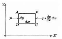
The Euler equations permit the deduction of an important result known as Bernoulli’s law.26 Stated simply, Bernoulli’s law implies that the pressure of the fluid increases when the velocity decreases, and vice versa. There are technical restrictions imposed on its application, but the law has many practical uses in aerodynamics. It lies at the basis of an important measuring instrument used for determining the speed of flow of a real fluid such as air. The instru­ment is called a Pitot-static probe and is used, for example, in wind tunnels to establish the speed of flow. Furthermore, every aircraft is equipped with this device in order to determine the speed of flight. The instrument registers pressures, but it yields information about velocities in virtue of the relation given by Bernoulli’s law.

Stated quantitatively, the version of Bernoulli’s law to which I have re­ferred is

p+1 pV2 = H,

where H is a constant called Bernoulli’s constant. The formula only strictly applies to the steady, irrotational motion of an ideal fluid. It refers, in the first instance, to a single streamline and relates the pressure and velocity at any point on the streamline to the value of H that characterizes the streamline. In aeronautics all the streamlines can be taken to originate from a region of constant pressure and velocity, and then all of the streamlines have the same value of H. The Bernoulli constant has the same value for all parts of the flow, and its value can be established for the entire flow if it is known for any given point in the fluid. The first term in the equation, p, is called the static pressure. The second term is called the dynamic pressure, and their sum, H, the Bernoulli constant, is the sum of the static and dynamic pressures and is therefore called the total pressure. The formula indicates that as the velocity V increases at some point in the flow, the static pressure p goes down at that point because the two quantities, p and (1/2) p V2, must always add up to the same value. Furthermore, by knowing the density p and the value of p and H, we can calculate V, the speed of the flow. This is evident because the formula can be rearranged and restated as

Подпись: У =2(H – p)

Both the static pressure (p) and the total pressure (H ) of a flow can be mea­sured. Figure 2.3 shows a simple arrangement of tubes and manometers that

Bernoulli’s Equation

would yield measures of these quantities. The total pressure measurement (a) uses an open-ended tube. The static pressure measurement (b) uses a closed tube with a small hole in its side. The side hole is called the static tap. Both tubes are connected to their respective manometers. The third part of the figure (c) indicates how the two measuring devices can be unified to form a Pitot-static probe. In the combined instrument, the single manometer mea­sures the pressure difference (H – p) needed to establish the velocity.

Measuring the speed of flow by means of a Pitot-static probe can be ac­curate to about 0.1 percent, but it has a slow response rate and demands care and suitable conditions. The formula contains a term for the density of the
air, and density varies with altitude, a fact of importance when the instru­ment is used in an aircraft to measure speed. Furthermore, the Pitot probe itself can disturb the flow it is used to measure. Small faults such as a burr around the mouth of the static tap, or a misalignment of the probe, as well as turbulence in the flow, can significantly affect the readings.27 Conditions such as the formation of ice in and around the inlet holes can also falsify the instrument readings of an aircraft, and for this reason such devices are usually equipped with electrical heating elements. The formula underlying the use of the Pitot-static probe, which I have given, only applies to airflows that can be considered as incompressible and has to be modified to allow for compression effects for high-speed subsonic flight. Yet further modifications are needed to correct for the presence of shock waves at the nose of the Pitot tube as the speed of sound is approached.28

Four Practical Men

In 1907 Herbert Chatley, lecturer in applied mechanics at Portsmouth Tech­nical Institute, published The Problem of Flight: A Text-Book of Aerial Engi­neering. The book went through two further editions, in 1910 and 1921. In the preface Chatley explained that, in terms of mathematics, he followed the practice, “well established in engineering,” of omitting factors that appear unimportant: “The formulae are therefore ‘engineering formulae’ in the strict sense of the word, i. e. they are not the result of a deep mathematical analysis which it is, in the majority of cases, almost impossible to apply.”67

Chatley’s account of lift was eclectic. It involved elements of perfect fluid theory and discontinuity theory along with the Newtonian analysis and its problematic sin2 formula. To overcome the difficulties he added various em­pirical corrections. These cut across the deductive links between the formulas in a manner that might have been calculated to offend the sensibilities of a wrangler. He began by mentioning the continuous flow of a perfect fluid over an inclined plane. This, said Chatley, is described in Lamb’s Hydrody­namics, and its reality has been demonstrated by photographs taken by Prof. Hele-Shaw. (In fact Hele-Shaw’s photographs show the behavior of a viscous fluid in slow motion between two glass plates that are very close together. Stokes was able to show that, under these conditions, “creeping motion,” as it is called, provides an accurate simulation of the flow of a perfect fluid. The forces at work and the boundary conditions are different, but the pho­tographs show what a perfect fluid flow would look like.)68 Chatley went on to assert that at greater speeds this flow breaks down and is replaced by one showing surfaces of discontinuity enclosing pockets of turbulence on the rear of the plate. These eddies reduce the pressure. So far, Chatley’s qualitative pic­ture is approximately that of Kirchhoff-Rayleigh flow, combined with some of Kelvin’s ideas about the turbulence in the dead-water region.

Chatley then introduced some mathematics and deduced Newton’s sin2 formula in the manner just described. What Chatley meant by an engineer­ing formula became clear when he asserted (without giving evidence) that the effect of the eddying on the rear of the plate is to augment the pressure by half as much again. He therefore repeated the above formula, but now multiplied by 3/2, and called it Nmax.. Chatley claimed that this formula agrees “very fairly” with some experimental results of Coulomb, although it was conceded that, for small angles, experimenters disagree greatly. In what is presumably a reference to Rayleigh’s paper, he went on: “The latest results are almost unanimous in making the variations of thrust as sin0 and not as sin2 0. All these following expressions are thus divided by sin 0” (29). Thus the sin2 0 term in the Newtonian formula was simply altered to sin0. In the 1921 edition this abrupt step was justified by saying that the original formula is approximately correct for large angles of incidence (from 60° to 90°), but for small angles, “owing to the continuity of the air, sin0 must be substituted for sin2 0” (31). In the 1910 and 1921 editions the reader was told that the end result is “practically correct” for plane surfaces and, with “slight correction to the coefficients,” also applies to curved surfaces.

Algernon Berriman was the chief engineer at the Daimler works in Cov­entry and the technical editor of Flight. In 1911 both Flight and Aeronautics published accounts of his lectures titled “The Mathematics of the Cambered Plane,” and in 1913 he published Aviation: An Introduction to the Elements of Flight.69 This book was based on lectures he had given at the Northampton Polytechnic Institute. Berriman also started from the Newtonian idea of ac­tion and reaction. Lift came from the reaction on the wing of the mass of air that was, by some means, forced downward by the wing. Thus, “the wing in flight continually accelerates a mass of air downwards, and must derive a lift therefrom.”70 The basic formula is Force = Mass X Acceleration, but how is this formula to be applied? What is the mass of air that is involved? The original Newtonian picture must have underestimated this mass, hence the underestimation of the lift that can be generated.

Berriman assumed that the wing sweeps out, and pushes down, a greater area than is suggested by the simple geometry of an inclined plane. The wing exerts an influence on “all molecules within an indefinite proximity to the plane; in other words a stratum of air of indefinite depth.”71 Instead of stating that a wing of area A engages with a quantity of air determined by the frontal projection A sin0, the assumption was made that it sweeps out a larger area, AS, whose sweep factor S is typically much larger than sin 0. Berriman said that “practical considerations” gave reason to believe that “the effective sweep of a cambered plane may be defined in terms of the chord of the plane” (5). In other words, Berriman put S = 1. This equation was based on the experience of the pioneers and experimenters, such as Langley, who found by trial and error that they got the best results with a biplane when they positioned one wing about one chord length above the other.72 The reasoning was hardly rig­orous, but the assumption allowed Berriman to avoid the troublesome sine – squared term.

Although the concept of “sweep” was popular with the practical men, it had few practical advantages. All that could be done was to determine the lift empirically and then deduce that the quantity called sweep must have such and such a numerical value. No one could go in the other direction. There was no way to predict the lift from the sweep. One might argue, inductively, that similar wings will have similar sweeps, but one could also say that similar wings have similar lifts, so in practice nothing is gained by introducing the concept. G. H. Bryan, after expressing irritation with Berriman’s casual way with trigonometric formulas,73 identified the source of the difficulty:

there is no such thing as “sweep” except in Newton’s ideal medium of non­interfering particles satisfying the sine squared law. In a fluid medium the disturbance produced by a moving solid theoretically extends to an infinite distance, gradually decreasing as we go further off. Mr. Berriman’s “sweep” is, physically speaking, an impossibility. If, however, “sweep” is defined as the depth of a hypothetical column of air, the change of momentum in which would represent the pressure on the plane, then the introduction of this new quantity is only a useless and unnecessary complication. Instead of facilitating the determination of the unknown data of the problem, it merely replaces one variable which is physically intelligible and capable of experimental determi­nation by another variable satisfying neither of these conditions. (265)

The practical men never found a way to use the idea of sweep so that they could sustain what Kuhn called a “puzzle-solving tradition.”74

The work reported in Albert Thurston’s Elementary Aeronautics of 1911 was based on the hope of identifying the significant properties of the flow, such as the sweep of a wing, in an empirical manner.75 Thurston had worked for Sir Hiram Maxim and then became a lecturer in aeronautics at the East London Technical College. He took numerous photographs of airflows made visible by jets of smoke as they streamed past objects of various shapes. The objects ranged from rectangular blocks to aerofoil shapes, or “aero-curves” as Thurston called them. He concluded that the important qualitative factor in the flow over a wing was that the entry at the leading edge was smooth and avoided the “shock” detectable in the case of a simple, flat plate. The avoid­ance of shock was possible because of the rounded and slightly dipped front edge characteristic of a wing, a shape whose advantages had been discovered empirically by Horatio Phillips and Otto Lilienthal.76 The essential thing, ac­cording to Thurston, was to maintain a smooth “streamlined” flow. The at­tempt to impose sudden changes in the velocity of the air merely produces surfaces of discontinuity (20). The photographs showed that with a good, winglike shape at small angles of incidence, “the air divides at the front edge and hugs both sides as it passes along; its resistance to change of motion caus­ing a compression on the lower side of the plane and a rarefaction or suction on the upper side. As the inclination is increased a critical angle appears to be reached, after which the stream line ceases to follow the upper side and forms a surface of discontinuity with corresponding eddies” (21-24).

As with the work of Eden, Bairstow, and Melvill Jones at the NPL, such photographs revealed that the model of discontinuous flow was not going to provide a basis for understanding lift. The photographs did, though, support ideas about the extended sweep of a wing. Thurston avoided using the word “sweep” but referred to the “field” of a wing and, on the basis of his photo­graphs, asserted: “The air affected by an aeroplane [= wing], that is the field of an aeroplane, is greater than the air lying in its path. Thus. . . it will be seen that air, which is considerably above the front edge of the plane, is within the range of the plane, and is deflected downwards” (26-27).

Even with photographs of smoke traces in the flow, it proved impossible to identify the sweep in a quantitative way, and the underlying causes of the qualitative effects visible in the photographs remained obscure. Thurston, however, was convinced that the secret of good design, both for wings and other components, was attention to streamlining, that is, ensuring that the lines of flow in the immediate neighborhood of the body coincide with the surface of the body. Like Chatley, Thurston drew on the work of Hele-Shaw to show how streamline flow works and what it looks like.77

Frederick Handley Page also appealed to Hele-Shaw’s photographs. Hand­ley Page was one of the celebrated pioneers in the British aviation industry. Despite its early inability to deliver BE2s, his firm was later to achieve fame for its manufacture of large bomber and passenger aircraft. In April 1911 he gave a lecture at the Aeronautical Society titled “The Pressure on Plane and Curved Surfaces Moving through the Air.”78 He began by discussing the re­sult that had caused so much difficulty for the discontinuity theory, namely, that the formation of “dead” air behind the plate happens when it has passed the critical angle. Practical aeronautics by contrast, said Handley Page, deals with small angles of incidence where the flow hugs the back of the plate or aerofoil. There is then a maximum of lift to drift and a minimum of eddy disturbance. Commenting on a Hele-Shaw photograph of the flow of a per­fect fluid past an inclined plane, Handley Page said, “The air on meeting the plane divides into two streams. . . the streams meeting again at the back of the plane. At high velocities the eddies and turbulence at the rear of the plane completely obscure this, but up to the critical angle at which the ‘live’ air stream leaves the plane back, the effect is still the same” (48).

Handley Page, like Chatley and Thurston, took ideal fluid theory to pro­vide an accurate picture of real flow round a wing, even when there are no surfaces of discontinuity or other complications such as vortices in the flow. Hele-Shaw’s photographs, however, depicted d’Alembert’s “paradox” in ac­tion, not a wing delivering lift. The practical men were thus walking into the trap that Greenhill had identified in his lectures at Imperial. They were proposing a picture of the flow which the mathematician would immediately recognize as one that gave neither lift nor drag.

No one in the audience at the Aeronautical Society mentioned this prob­lem in the subsequent discussion. Even if the point had been raised it would have had little impact on Handley Page’s eclectic argument because, immedi­ately after this appeal to hydrodynamic theory, the perspective was changed. He adopted the neo-Newtonian approach but suggested refining the idea of sweep by dividing it into two parts. This modification revealed his real inter­est in the Hele-Shaw pictures. The portrayal of the flow at the leading edge suggested to Handley Page that two different processes were at work. There was the sweep associated with the flow upward from the stagnation point to the leading edge, and the sweep associated with the downward flow toward the rear edge. This complication enabled him to refine the mathematics of the sweep picture, but it did not get round Bryan’s objections: it merely doubled the number of unknowns. Handley Page still had to infer the total sweep from the observed lift and had no way to apportion the contributions of the two components of the sweep that he postulated.

Handley Page’s lecture was generally well received, though no mathemati­cians contributed to the discussion—if, indeed, any were present. Cooper, who had been so scathing about Greenhill, congratulated Handley Page on getting a formula that applied to experimental results: “it is not everybody,” he added, “who does that.” Cooper was either being polite or had failed to see how little had been achieved. He went on to say that he thought Handley Page’s analysis applied more to the flat plate, where the leading edge caused a “shock” in the flow, than it did to an aerofoil with its rounded, dipping front edge. Here, claimed Cooper, the stagnation point would be on the very front, not below the leading edge on the underside of the wing, as it was in Hele – Shaw’s picture of the plate. In what may have been meant, at least in part, as a response to this point, Handley Page said, “It seems to me that the entering front edge is only a kind of transformer. . . a curved plane is more efficient than a flat one because you have a more efficient transformer” (63). Unfortu­nately, no attempt was made to explain the metaphor of the “transformer.”

A few years after this exchange Handley Page introduced the famous, and commercially lucrative, Handley Page wing. The standard wing was modified by introducing a slot along the leading edge which changed the flow at the leading edge by directing air from underneath the front of the wing onto its upper surface. It was, in effect, a small extra aerofoil that ran along the leading edge of the main wing. The resulting change in the flow significantly increased the lift and delayed the stall.79 Could this innovation have been a result of the earlier conception of the leading edge as having a capacity to “transform” the flow? When Handley Page described his invention in the Aeronautical Journal, he made no mention of the metaphor of the transformer. Indeed, he never gave a clear account of the thought processes behind his invention, so the question must remain unanswered. (He had originally tried making slots that ran from the leading edge to the trailing edge, that is, along the chord of the wing rather than along the span. This suggests that the process of inven­tion was trial and error, rather than theory-led.) The value of the leading – edge slot is an example of that intriguing phenomenon “simultaneous dis­covery” and, almost predictably, gave rise to a priority dispute.80 The slot was developed independently in Germany by G. Lachmann, and for many years Thurston also argued his claim to be recognized as the inventor.81

A Precedent

Lanchester’s critics insisted on reading his work as an exercise in inviscid fluid theory. Bryan, Taylor, Bairstow, Cowley, and Levy all made this move. This should be puzzling. It must have been evident to any reader of Lanchester’s book that he was not simply thinking in terms of perfect fluids. He was con­stantly moving back and forth between viscous and inviscid approaches, try­ing, as it were, to negotiate some rapprochement between them. How could this have been overlooked? One answer is that it was not overlooked at all. Perhaps it was perceived clearly but seen as a weakness in the text. The inclu­sion of both viscous and inviscid strands in the argument may have seemed like mere ambiguity. Reading Lanchester as a purely inviscid theorist may have been a way to repair the ambiguity. Wouldn’t this be a natural thing for mathematically sophisticated readers to do?

There may be some truth in this suggestion, but it cannot be the whole story. It does not explain why the ambiguity was resolved by turning Lan – chester into an exponent of the inviscid approach rather than an exponent of a viscous approach. Either would have resolved the ambiguity, so why did the inviscid reading prevail? Here is a possible answer to that question. There was a precedent for the preferred assimilation, namely, the received understanding of Rayleigh’s paper on the irregular flight of the tennis ball. Rayleigh had done exactly what Lanchester had done, that is, work with an informal mixture of ideal-fluid theory and viscous considerations. The math­ematics of Rayleigh’s tennis ball paper dealt with an inviscid fluid, but the circulation described by this mathematics could not have arisen from any processes conceptualized within it. Friction was needed to account for the circulation. The fluid was therefore taken to be viscous at one point in the account and inviscid at another point, thus rendering the argument logically inconsistent. How did readers respond to this oscillation between viscous and inviscid fluids? In Cambridge the tennis ball paper was absorbed into the literature on inviscid theory. The ambiguity was resolved by playing down the appeal to viscosity and treating the analysis as if it began at the point where a circulation could be taken as a given. This approach had the virtue of focusing on the part of the work that was easiest to develop mathematically, and indeed it may explain why the assimilation went this way rather than the other. It was in these terms that Rayleigh’s tennis ball result found its way into the Cambridge examination papers.6

Section iv. the lift on the curved surface

Having arrived at the value of the circulation, Kutta immediately multiplied the circulation by the density of the air and the speed of flight to give the lift. He did not state the relevant formula, L = p V Г (where Г = circulation), but he used it implicitly. Here, then, was the lift on a Lilienthal-type wing specified in terms of known quantities: p, the density of the air; V, the speed of flight; r, the radius of the circular arc of the wing; b, the length of the wing; a, which was half the angle subtended by the arc; and p, the angle of incidence. The formula was

а (а і

Lift = 4npV2rbsin—sinI ~+P •

Kutta did not simply take the general lift formula p УГ for granted. He an­nounced that he was going to offer a general proof based on energy consid­erations, which he proceeded to do. The proof not only gave the magnitude of the resultant aerodynamic force as the product of density, velocity, and circulation, but it also carried the implication that the force must be at right angles to the direction assumed by the free stream at large distances from the wing.31 In other words: there was no drag. Given that Kutta was treating the air as an ideal fluid in irrotational motion, this result was a necessary conse­quence of his premises.

Kutta now had to confront a logical problem. If the fluid is perfect it will slide effortlessly over any material surface. This means that it can only exert a force normally to the surface. Consider a flat plate in a steady flow of ideal fluid and add a circulation around the plate. Suppose that the flow at a dis­tance from the plate is horizontal and that the plate has an angle of attack p to this flow. If the forces on the plate are normal to the plate, then won’t the resultant R be normal to it? It will be tilted back at an angle p to the verti­cal (see fig. 6.3). The resultant R will then have a drag component of R sinp. This contradicts the result of the general lift theorem, which Kutta had just proved, where the resultant is vertical, that is, normal to the flow but not

Section iv. the lift on the curved surface

ate a drag and contradict the Kutta-Joukowsky law of lift, according to which the resultant aerodynamic force must be normal to the flow, not the plate.

normal to the plate, so that the drag component is 0. Kutta was primarily considering an arc, not a flat plate, but the same result holds even though the geometry is more complicated. Much of the rest of his paper was spent exploring this apparent paradox.

Kutta said there was no contradiction because the force resulting from the normal pressures was not the only force at work. There must also be another force that operates on the very tip of the plate, hence his remark in the intro­duction when he said that the lift had two components. Kutta thus identified a suction force that was tangential to the surface at the leading edge. When this force is combined with the normal pressure forces, the resultant is verti­cal. The forward component of the suction counterbalances the backward component of the pressure forces to produce the zero-drag outcome. Again, the situation can be seen more simply with a flat plate. The tangential suction and the normal pressure forces on the plate are shown in figure 6.4. Intro­ducing the leading-edge suction restores consistency with the results of the kinetic energy proof that Kutta had provided for the law of lift.32

Kutta did not treat the leading-edge suction as a mere device to avoid a problem. He proceeded to investigate the flow field near the leading edge by introducing various approximations and assumptions about the shape of the streamlines. An idealized fluid flowing around an idealized, sharp edge would have an infinite speed. This would produce an infinitely large suction force concentrated on an infinitely small area, which suggests that the math­ematics would assume the indeterminate form ^/0. By reasoning that the approximate shape of the streamline would be that of a parabola, Kutta used the results he had already established to argue that the actual force would

Подпись: FIGURE 6.4. The “paradox” resolved. There must be another force at the leading edge. The normal pressure on the plate plus the suction force at leading edge give a resultant normal to the flow (but not normal to the plate).

converge to a determinate and finite value. He deduced that this value was exactly that which was required to turn the backward-leaning pressure resul­tant into a vertical lift and to give it the magnitude predicted by the general lift theorem.

The Elliptical Distribution of Lift

Ideally the shape of the graph of Г(х) showing the distribution of circula­tion, and hence lift, along the span of the wing, would be deduced from first principles. The deduction would start with the governing equations of fluid motion and, by inserting data about the shape of the wing and the angle of attack, the mathematics should yield the function Г(х) relating the circula­tion to the x-coordinate along the span. This, said Prandtl later, was the first question that he and his group posed for themselves but the last one to be answered. (During the war the problem was solved for a rectangular wing by Betz. His analysis formed the substance of a 1919 inaugural dissertation submitted to Gottingen.)73 Initially, however, it was necessary to proceed by trial and error and under the guidance of experiment. The character of the lift distribution along the wingspan could be established empirically by pressure measurements made on a model of the wing in a wind channel. If a math­ematical representation could be found for the distribution, and if that func­tion could be integrated, then the equations of the theory (given in the last section) could be employed to deduce further characteristics of the wing. The function Г(х) governing the distribution of circulation had to be (1) empiri­cally plausible and (2) mathematically tractable. Experimentally it transpired that most of the wings used in practice had a similar distribution of lift and hence circulation along their span. There was a strong “family resemblance” between their distributions, and the family in question was well known.74 The distribution typically resembled the upper half of an ellipse. The expression Г(х) is essentially nothing more than the equation for an ellipse.

The equation for an ellipse is simple. Using standard x – and y-coordinates,
the ellipse that has a major axis of length b in the x-direction and a minor axis of length a in the y-direction is represented by the equation

f—T+(—T=l

1 b/2 j fa/2j

The Elliptical Distribution of Lift

The ellipse is shown in figure 7.12a. If the y-axis is used to represent the circu­lation, then the formula describing an elliptical distribution of circulation of the kind shown in figure 7.12b is, by analogy,

The ellipse has one semi-axis of length Г0 (the maximum circulation) and the other semi-axis of length b/ 2 (the half span). This formula can be manipulated

Подпись: xThe Elliptical Distribution of LiftПодпись: (b)Подпись: FIGURE 7.12. The geometry of an ellipse provides a model for the lift distribution (a). In (b) there isПодпись:The Elliptical Distribution of Lift(a)

Tietjens 1931, 213. (By permission of Springer Science and Business Media)

to give an expression for Г (as a function of x). An elliptical lift distribution is thus given by

rM■

With this formula at hand, the reasoning set out in general terms in the previous section can be reworked to produce quantitative predictions about lift and induced drag. Following this line of reasoning, Prandtl was able to generate three important results. First, he showed that the induced drag along the span of a wing should be constant if the distribution of circula­tion is elliptical. Second, he showed that under these conditions the induced drag should increase according to the square of the lift coefficient. Third, he predicted a relation between the induced drag and the planform of the wing. He showed that induced drag should be inversely proportional to the aspect ratio. The narrower the wing, the lower the induced drag. This result had immediate implications for the aircraft designer. I shall now show how he reached these conclusions mathematically and then say more about their importance.

Differentiation of the formula for Г(х) gives the expression dr/dx, and the result can be substituted into the formula for the induced velocity, or downwash, that was arrived at in the previous section. The differentiation of the elliptical distribution gives

dr 4Г0 x

dx b (l-4×2/ b2 )1/2’

The induced velocity is then

p +b/2

Подпись:—у f —– ^—– dx.

nb — b/2 (l — 4×2/b2) )x’ — x)

The next problem was to evaluate the complicated-looking integral in order to give an actual value to the downwash. It turned out that the integral re­duced to a very simple expression. It was equal to – nb/2. The induced veloc­ity at the point x’ of the wing was then

Г

^’)=—20.

The induced angle of incidence for this point on the wing follows im­mediately:

w Г

q>(x’) = = ——.

V 2bV

Two features of these formulas for w and ф deserve notice. First, inspec­tion shows that all the quantities that enter into them are constants. The span of the wing, the speed of the free stream, and the value of the circulation at the center of the wing do not change as different positions along the span come under consideration. Both expressions are therefore independent of x’. It follows that for any given wing, provided it has an elliptical lift distribution, both the induced velocity and the induced angle of incidence are constant along the span. The unreal, infinite, induced velocities at the wingtip have been avoided. This was progress.

The second point of note is that both of the formulas have b, the span of the wing, in the denominator. Thus, as b approaches infinity, both w and ф approach zero. The theory therefore implies that for an infinite wing there will be no downwash, that is, no induced velocity, and thus no induced drag. This fits perfectly with the previous work of Kutta and Joukowsky. For an in­finite wing moving through an ideal fluid, the absence of induced drag means the absence of all drag, and this was one of the more disconcerting conse­quences of their analysis. However, the results of the two-dimensional theory turn out to be a limiting case of the more realistic, three-dimensional theory. On Prandtl’s approach, Kutta and Joukowsky were not studying the unreal aerodynamics of an imaginary world; they were studying the aerodynamics of the real world but dealing with limiting cases.

The value of the circulation Г(х) given earlier by the formula for the el­liptical distribution can be inserted into the Kutta-Joukowsky law. This gives an expression for the total lift of a wing with an elliptical distribution:

Lift = pVT0 J I 1 – — I dx ■

A change of variable simplified the integration and gave Lift = pVT0

If the lift is now expressed as a coefficient and the equation is rearranged to give an expression for Г0, the maximum circulation, it becomes
2VFCl

Подпись:bn

where F is the area of the wing. This value of Г0 can be inserted into the pre­viously derived expression for the induced angle of incidence, which gives

.C

nb2

This expression yields a relation between the induced angle of incidence and the planform of the wing.

Because of its importance it is worth making this relation explicit and restating the formula. For a rectangular wing of, say, span b and chord a, the area F = ab and the aspect ratio is b/a. This definition of the aspect ratio can be generalized for more complicated shapes. For wings that do not have a constant chord, the chord length can be replaced by F/b, that is, the area divided by the span, thus giving the aspect ratio as b2/F. If the aspect ratio is represented by the symbol AR, then the above formula for the induced angle of incidence becomes

This expression reaffirms the point made previously—that for a wing with an elliptical distribution, the induced angle of incidence will be constant along the span. The utility of the new formulation, however, is that it leads to a revealing expression for the induced drag. To arrive at this result it is only necessary to insert the above expression for ф into the formula for the coef­ficient of induced drag given previously. In the last section it was shown how Prandtl’s theory had given the following general result for the coefficient of induced drag:

2 +bl2

CD = — J Г(х)(p(x)dx.

Because an elliptical distribution for the circulation has been assumed, all of the component parts of this integral are now known. The expression for ф is a constant whose value has just been expressed in terms of the aspect ratio. It can thus be taken out from beneath the integration sign. The remaining integral of the elliptical shape Г(х) has already been evaluated. These results

The Elliptical Distribution of Lift The Elliptical Distribution of Lift

can be combined so that (again using AR to signify the aspect ratio) the coef­ficient of induced drag can now be written in the form

This formula expressed a highly significant result. It indicated two things. First, it showed that the induced drag increases rapidly with increased lift. The drag grows with the square of the lift coefficient. Second, it implied that to reduce the drag it was necessary to increase the aspect ratio of the wings. It therefore carried an important lesson for the aircraft designer because it linked a specific design feature of a wing to definite aerodynamic effects. The significance of the aspect ratio of a wing had long been recognized at an empirical level, but now a fundamental, theoretical understanding was emerging.

This deeper understanding had a typically engineering character to it. It identified the need to trade one advantage against another advantage. It pointed to the costs that had to be paid and the compromises that had to be made to get the benefits of increased lift and decreased drag. Increased lift brought increased induced drag. Induced drag could be reduced by in­creasing the aspect ratio, but an engineer would immediately see a problem. High aspect ratio may be desirable, but a long, narrow wing is not easy to build. Such a wing confronts the designer with the problem of how to make it strong enough without making it too heavy.

Glauert versus Taylor

There was clearly a desire by the members of the Aeronautical Research Committee to put the theory of circulation and Prandtl’s analysis of the finite wing to the test, but disagreement emerged about how to proceed. This gave rise to a sequence of technical reports in which Taylor and Glauert crossed swords. Part of the problem concerned experimental technique. A further difficulty was that Glauert was sensitive to the fundamental distinction be­tween the ideas underlying the two-dimensional picture of Kutta flow (that is, flow that is smooth at the trailing edge) and Prandtl’s three-dimensional picture of the wing as a lifting line with trailing vortices. Glauert wanted these ideas kept distinct, while other participants in the discussion ran these two ideas together and counted them as forming one single theory whose basic assumption was the irrotational character of the flow.

To explain what was at issue it is necessary to go back to December 1921 and the mathematical report submitted by Muriel Barker.4 She had suggested that the theoretical streamlines she had plotted for the flow over a Joukowsky aerofoil with circulation could be the basis for an experimental test: “it would be most instructive,” she had written, “if these same quantities could be ob­tained practically” (3). Miss Barker’s report and the question of what to do next were discussed by the Aerodynamics Sub-Committee and by the full Research Committee during February and March 1922.5 Should they follow her suggestion and place a model of a Joukowsky aerofoil in a wind channel or should they use a more practical aerofoil, for example, the RAF 15? If they used a real section then should they ask Miss Barker to generate the theoreti­cal streamlines by tedious computation or could a quicker method be found? Were mechanical or electrical methods of generating the theoretical stream­lines of comparable accuracy to those produced by the laborious calculations that would be needed? Lamb was in favor of using the Joukowsky profile and direct calculation. Southwell wanted to use a more realistic profile and a me­chanical method. He mentioned that Taylor had developed a piece of appara­tus that enabled him to use a soap film to model the potential surfaces of ideal fluid flow. Bairstow added that he and Sutton Pippard had devised graphical methods for solving Laplace’s equation.6 Then there was the possibility of using the techniques developed by Hele-Shaw derived from photographs of creeping flow. It was decided that Southwell and Taylor would report back on different analogue methods of producing theoretical streamlines.

Southwell started with his report T. 1696.7 He supported Muriel Barker’s suggestion that comparisons be made of theoretical and empirical stream­lines for an infinite wing, that is, where the model wing would reach right across the tunnel to exclude the effect of flow around the tips. In this way, said Southwell, “a direct check can be imposed upon one of the fundamental assumptions of the Prandtl theory” (2). Southwell then described the method developed by Taylor for simulating the streamlines and the bench-top ap­paratus that had been built.8 A soap film was stretched between the walls of a box while precise measurements were made of the position of the film. The film connected the outline of a small wing profile to other boundaries within the confines of the box. (These boundaries represented the walls of the wind tunnel.) Southwell explained how this technique could take into account the circulation as well as automatically correcting for the effect in the flow of the tunnel walls. “Using orthodox mathematical methods,” said Southwell, “it would appear that the problem thus presented is one of extreme difficulty”

(2) . Taylor, however, followed this up with a brief note, designated T. 1696a, in which he said that he had actually applied the soap-film method to a model aerofoil but had not taken the matter further.9 The small size of the apparatus prevented the measurements being made with the required accuracy. Tay­lor therefore backed the use of an electrical method, and eventually such a method was developed by E. F. Relf and formed the basis of the experimental comparisons that were later published.10

At this point Glauert intervened. In May 1922 he submitted his “Notes on the Flow Pattern round an Aerofoil” (T. 1696b).11 First, he took issue with Southwell’s claim that it would be difficult to allow for the influence of the channel walls by use of analytical methods. Glauert said that the effects could be represented in a simple way using standard mathematical techniques, the so-called method of images. He then went on to make some comments about the proposed experimental comparison involving an infinite wing and two­dimensional flow. It was important “to have a clear understanding of its bear­ing on the general question of aerofoil theory” (2). The implication was that some of the thinking behind the proposal lacked the requisite clarity. Not every test of the two-dimensional work was automatically a test of the three­dimensional claims, for example, the hypothesis that the flow over a wing is smooth at the trailing edge is not a necessary presupposition of Prandtl’s work. Prandtl used the idea that lift is proportional to circulation and that the circulation around a wing can be replaced by the circulation around a line vortex, that is, that the chord is negligible. But, said Glauert, no assump­tion is made “as to the relationship between the form and attitude of the aerofoil and the circulation round it, the analysis always being used only to estimate the behaviour of one aerofoil system from the known behaviour of another system of the same aerofoil section” (2). Taken in its own terms, he went on, the Prandtl theory has been applied “with considerable success” to three cases: (1) the effect of changes of aspect ratio, (2) the estimation of the behavior of multiplane structures on the basis of monoplane data, and (3) the description of flow patterns such as downwash. The comparison of predicted and observed data shows that the “agreement is reasonable.” This, Glauert insisted, constitutes “a satisfactory check of the fundamental equation” (3).

Glauert acknowledged that the hypothesis that the rear stagnation point is on the trailing edge overestimates the circulation and therefore the lift. It does so because of departures from the idealized condition of irrotational flow. The real flow detaches itself from the top surface of a wing before reach­ing the trailing edge and forms a “narrow, eddying wake behind the aerofoil.” Glauert had discussed this in his earlier report, “Aerofoil Theory,” but the committee seemed to be using the well-known facts about the existence of a turbulent wake as an objection to Prandtl’s work. If the wake really was to be a focus of interest, it would be necessary to make assumptions about the distribution of vorticity associated with “the contour of the aerofoil and in­side the wake region.” Prandtl’s aim was to give a first-order approximation for the flow at a distance from the aerofoil, and at points outside the wake. The vorticity of the aerofoil can then be concentrated at a point or, in the three-dimensional case, in a line, just as Prandtl assumed. It is legitimate un­der these circumstances to “ignore completely the series of alternative small vortices in the wake” (4). Glauert concluded by saying that the proposed ex­periment on an infinite wing would, indeed, illuminate the relation between aerofoil sections and the circulation round them, “but will not have any bear­ing on Prandtl’s aerofoil theory” (4).

Taylor did not agree. He produced a written reply, designated T. 1696c, in which he challenged both Glauert’s response to Southwell about mathemati­cal techniques and Glauert’s claim that the experiment would be irrelevant to Prandtl’s theory.12 On the latter point, Taylor declared that all the reasons Glauert “brings up to support his view were well known to most of the Com­mittee which discussed the proposed experiments and some of them were actually brought up in the discussion. It is curious, therefore, that Mr. Glau – ert should come to a view which is different from that of the members who proposed the experiments” (1).

Taylor said that the experiment on the infinite wing would constitute a test of Prandtl’s theory because the theory was based on the assumption

Glauert versus Taylor

figure 9.1. G. I. Taylor (1886-1975). Taylor, a Trinity mathematician, had dismissed Lanchester’s ap­proach in his Adams Prize essay of 1914. In the postwar years Taylor acted as an astute and creative critic of the new theories in aerodynamics and the experimental evidence advanced in their favor. (By permission of the Royal Society of London)

that the flow at a distance from the wing was irrotational. Glauert’s posi­tion, it seemed to Taylor, was that this assumption can be made a priori, but it cannot. It is an empirical matter, and the proposed experiment was designed to test it. Second, Glauert had said that the experimental evidence gathered so far had provided a satisfactory check on the fundamental equa­tions of the theory. Taylor replied that if “satisfactory” meant “sufficient” he could not agree. The fundamental equation L = p V Г, relating lift and circu­lation, might hold true for some body of data, and some experimental ar­rangement, but not for the reason that Prandtl had given, that is, not because the flow was irrotational. In fact, said Taylor, “there are an infinite num­ber of kinematically possible distributions of velocity for which this is the case, but only certain of them will correspond with irrotational motions”

(3) . Finally, Taylor turned to Prandtl’s assumption that the chord of the wing could be neglected. Again, insisted Taylor, this could not be assumed a pri­ori. “The assumption can only be justified by experiment or by calculation of the type indicated by Miss Barker or by the purely empirical method of comparing the results of Prandtl’s calculations with observed lifts and drags”

(4) . For these reasons, said Taylor, “I do not agree with the conclusions reached by Mr. Glauert.”

Subcultures and Status

One of the subcultures I identify in my explanation (German technical me­chanics) belongs to the general field of technology, while the other (British mathematical physics) falls more comfortably under the rubric of science. My explanation therefore presupposes a society in which technological and sci­entific activity are understood to be different from one another. The picture is of culture with a division of labor in which the roles of technologist and scientist are treated as distinct or distinguishable. These labels are the catego­ries employed by the historical actors themselves. Their role in my analysis derives from their prior status as actors’ categories.15 Although the members of the two subcultures interact with one another, my data justify attributing a significant degree of independence to them. To speak of “subcultures” car­ries the implication that the practitioners within each respective subculture routinely draw upon the resources of their own traditions as they perform their work and confront new problems.16 A symmetrical stance requires that both science and technology be placed on a par with one another for the pur­poses of analysis. This injunction is directed at the analyst and is consistent with the historical actors themselves according a very different status to the two activities: for example, some of the actors may see science as having a higher status than technology. The point of the methodological injunction to be “symmetrical” is that it requires the analyst to ask why status is distributed in this particular way by the members of a group and to keep in mind that it could be distributed differently.17

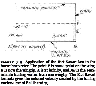
Attributions of status can be expressed in subtle ways. They may take the form of assumptions (made by both actors and analysts) about the depen­dence of one body of knowledge on another. Is technology to be seen as the (mere) working out of the implications of science? Is the driving force of tech­nological innovation typically, or always, some prior scientific innovation?18 An inferior status may be indicated by an alleged epistemological dependence and a reluctance to impute agency and spontaneity to technology. The sym­metry postulate does not assert the truth or falsity of any specific thesis about dependency or independence, but it does require that such a thesis is not in­troduced into the analysis as an a priori assumption. At most the dependency of technology on science is merely one possible state of affairs among many other possibilities; for example, science may depend on technology rather than technology on science, or the two may be completely fused together or completely separate. The actual relation is to be established empirically for each episode under study. In the case of the theory of lift it is clear that the technologically important ideas worked out by Lanchester, Kutta, and Prandtl were not the result of new scientific developments. On the contrary, they exploited an old science and old results, namely, ideal fluid theory, the Euler equations of inviscid flow, and the Biot-Savart law. The shock engen­dered after the Great War by the belated British recognition of the success of this approach was not the shock of the new but the shock of the old.19 The science that was exploited was not only old; it was also discredited science— discredited, that is, in the eyes of Cambridge mathematical physicists pushing at the research front of viscous and turbulent flow.

The advocates of the circulatory theory of lift brought together the ap­parently useless results of classical hydrodynamics and the concrete prob­lems posed by the new technology of mechanical flight. The theory of lift in conjunction with the theory of stability constituted the new science of aero­nautics. Given the way that scientific knowledge was harnessed to techno­logical concerns, the new discipline might be called a technoscience. Some commentators have argued that “technoscience,” the fusing of science and technology, is a recent, indeed a “postmodern,” phenomenon, exemplified by the allegedly novel patterns of development shown in information tech­nology and computer science. Others have argued that, because the division of labor between science and technology is a relatively recent development, so their fusion into “technoscience” is, in fact, a return to the original con­dition of science.20 Did not science, in its early modern form, derive from a fusion of the work of the scholar and the craftsman?21 Whether or not this account of the origins of science is true, identifying early twentieth-century aerodynamics as an instance of technoscience would support the thesis that technoscience is not a novelty.

In the 1930s Hyman Levy, who had earlier coauthored Aeronautics in The­ory and Experiment, wrote a number of books of popular science. Along with Bernal, Blackett, J. B. S. Haldane, Hogben, and Zuckerman, Levy belonged to a remarkable group of scientists who played a significant role in British cultural and political life during the interwar years.22 One of Levy’s books was titled Modern Science: A Study of Physical Science in the World Today.23 Aero­dynamics was one of his main examples. He did not call it a technoscience, but he did offer it as an exemplary case of the unity of theory and practice. Writing from a Marxist standpoint, he cited the work of Prandtl and von Karman and offered the strange transitions from laminar to turbulent flow as evidence that nature embodied the laws of dialectics. While it is plausible to see the later developments of aerodynamics as moving toward a unification of theory and practice, the fact remains that in the early years there was a dis – cernable difference between the stance of the mathematical physicists and the engineers. The history of Levy’s contributions, and his own earlier, negative stance toward the circulation theory, underlines this point. When Levy was active in the field and working at the National Physical Laboratory, there was still a significant difference in approach between mathematical physicists and technologists—at least, between British mathematical physicists and German technologists.24 It is clear that behind the emerging “synthesis” of theory and practice, there still lay the “thesis” of mathematical physics and the “antith­esis” of engineering. Historical contingency rather than historical necessity determined the balance between them. I now look at one such contingency.

Mathematicians versus Practical Men:. The Founding of the Advisory. Committee for Aeronautics

In the meantime every aeroplane is to be regarded as a collection of unsolved math­ematical problems; and it would have been quite easy for these problems to have been solved years ago, before the first aeroplane flew.

g. h. bryan, “Researches in Aeronautical Mathematics” (1916)1

The successful aeroplane, like many other pieces of mechanism, is a huge mass of compromise.

Howard t. wright, “Aeroplanes from an Engineers Point of View” (1912)2

The Advisory Committee for Aeronautics (the ACA) was founded in 1909. This Whitehall committee provided the scientific expertise that guided Brit­ish research in aeronautics in the crucial years up to, and during, the Great War of 1914-18. From the outset the ACA was, and was intended to be, the brains in the body of British aeronautics.3 It offered to the emerging field of aviation the expertise of some of the country’s leading scientists and engi­neers. In 1919 it was renamed the Aeronautical Research Committee, and in this form the committee, and its successors, continued to perform its guid­ing role for many years. After 1909 the institutional structure of aeronauti­cal research in Britain soon came to command respect abroad. When the United States government began to organize its own national research effort in aviation in 1915, it used the Advisory Committee as its model.4 The result­ing American National Advisory Committee for Aeronautics, the NACA, was later turned into NASA, the National Aeronautics and Space Administration. The British structure, however, was abolished by the Thatcher administration in 1980, some seventy years after its inception.5

If the Advisory Committee for Aeronautics was meant to offer the best, there were some in Britain, especially in the early years, who argued that, in fact, it gave the worst. For these critics the ACA held back the field of Brit­ish aeronautics and encouraged the wrong tendencies. The reason for these strongly divergent opinions was that aviation in general, and aeronautical sci­ence in particular, fell across some of the many cultural fault-lines running through British society. These fault lines were capable of unleashing powerful

and destructive forces. From the moment of its inception the Advisory Com­mittee was subject to the fraught relations, and conflicting interests, that divided those in government from those in industry; the representatives of the state from those seeking profit in the market place; the university-based academic scientist from the entrepreneur-engineer; the “mathematician” and “theorist” from the “practical man.” Throughout its entire life these struc­tural tensions dominated the context in which the ACA had to work.6

Lines of Equal Potential

Suppose the mathematician has managed, by good fortune or guesswork, to write down the stream function for a steady flow of fluid under certain boundary conditions. By equating the stream function to a sequence of con­stants, a family of streamlines can be drawn and a picture of the flow can be exhibited. Now suppose that, guided by the streamlines, the mathematician draws another family of curves. These new curves are to be drawn so that they always cut across the streamlines at right angles. A network of orthogonal lines is built up. If the first set of lines were the streamlines of the flow, what are these new lines that have been drawn so that they are always at right angles to them?

They are called potential lines. They are in fact another way of implic­itly representing the velocity distribution of a flow. Their immediate interest is that the potential lines of a given flow can always be reinterpreted as the streamlines of a new flow, while the old streamlines become the potential lines of the new flow. Streamlines and potential lines can be interchanged, provided that appropriate changes are made to the boundary conditions of the flow. This possibility of interchange can be interpreted to mean that, just as there exists a stream function, so there must exist another, closely related function ready to perform the same role with regard to the lines of potential that у played with regard to streamlines. This function is called the potential function, and it is conventionally designated by the Greek letter phi, ф. The role of the potential function may be illustrated by the uniform flow along the x-axis, where the axis can be taken as a solid boundary. This flow is the one discussed earlier whose stream function is у = – Uy. The streamlines are
horizontal lines parallel with the x-axis, so the potential lines are vertical lines parallel with the y-axis. Now switch the potential lines and the streamlines, that is, switch the two families of curves given by у = constant and ф = con­stant. The streamlines are now vertical and parallel with the y-axis, which can be treated as a boundary to the new flow. The horizontal lines parallel with the x-axis are the new potential lines.

Lines of Equal Potential Подпись: —дф and dx

The intimate relationship between potential lines and the streamlines finds expression in the mathematics of irrotational flow. Because the two families of curves are orthogonal, it is possible to write the equations for the velocity components u and v of a given flow either in terms of the stream function that applies to the flow or in terms of the potential function that applies to it. The result gives rise to the following relationships between ф and у:

= dy = дф dx dy

It follows immediately from these equations that the potential function ф obeys Laplace’s equation, just as the stream function does when represent­ing an irrotational flow. One useful mathematical property of solutions to Laplace’s equation is that they are additive. If yj is a solution and y2 is a solution, then y3 = yj + У2 is also a solution. Stream functions can be added. Again, the point can be illustrated by reference to the simplest possible cases. The flow of speed U along the x-axis (yj = – Uy) can be combined with, say, a flow of the same speed U but along the y-axis (that is, the flow arrived at by switching the streamlines and the potential lines of the original flow so that y2 = Ux), and the result is another flow that moves diagonally and whose stream function is y3 = yj + У2. In this way complicated flows can be con­structed out of simple flows.