an has dreamed of flying since deep antiquity. Man’s restless spirit felt challenged to master an environment God had denied, and to move in three dimensions at a speed immeasurably greater than possible on the earth’s surface. The deep blue of the sky fascinated the eye and excited human imagination.
It was probably the thirst for flight that produced the beautiful and didactic story of Icarus. Told more than two millennia ago by Roman poet Ovid, it is the first recorded expression of the idea of flight.
In 750BC, Cretan King Minos invited Greek sculptor Daedalus to construct a Labyrinth so elaborate as to render any escape impossible. Daedalus arrived on Crete with his son Icarus, and in fulfilling his commission created one of the Wonders of the World.
Reluctant to part with so accomplished a master, Minos did all he could to prevent his return. However, Daedalus decided to flee in a way the tyrant could not foresee. He gathered birds’ feathers and glued them together with wax, making pairs of wings for himself and Icarus. Training his son for the flight, he told
|

The legend of Icarus: a source of inspiration and a challenge to human ingenuity
|
|
him he would be safe at a height where neither waves would wet the feathers, nor solar heat would melt the wax.
Came the day of the flight, and the pair set off successfully. But when the best part of the journey was behind them, Icarus, taken with the experience and forgetting his father’s advice, shot upward towards the searing sun. The hot rays soon melted the wax, the wings melted, and the sea claimed the youth’s body. Ever since, a portion of the Aegean bears the name of Icarus.
The freedom that flight grants bestows many benefits in battle. Ancient strategists knew this. Their attempts to use flight in warfare employed neither aircraft, nor aerostatics and tethered balloons. It was the kite, invented in China 2300 years ago, that was used by the soldiers of the day to take observers aloft for the purpose of spying on enemy movements. Thirteenth Century Italian traveller Marco Polo observed such an ascent during his journey around China. The same nation also invented missiles (rocket propelled arrows) in time to use them with some success against Mongol invaders in 1232AD.
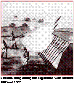
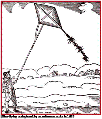 Kites and rockets later spread to medieval Europe. There is no written confirmation that Europeans used kites to haul men aloft. However, rockets had been tested in battle by the middle of the 15th Century. Though fitted with fins, up until the late 19th Century they were unstable and imprecise, and this inhibited their popularity among soldiers.
Be tween 1475 and 1505, scientific genius Leonardo da Vinci worked on the problem of enabling man to inhabit the air and descend safely. His paper entitled On the Flight of Birds dealt in part with how man could copy birds’ movements and hence their ability to fly. Arriving at certain conclusions, Leonardo described and drew apparatus for flying. His orni – thopter had the body of a boat, controllable tail surfaces, and a retractable
undercarriage. Borrowing from nature,
 Leonardo formulated principles of lift, and methods of attaining stable controlled flight. In order to increase the sweep of each wing stroke, he employed the combined strength of arms and legs. In his declining years, aware of man’s inadequate and waning physical prowess, the genius directed more attention to fixed wing flying machines. In the closing year of the 15th Century, he devised an ornithopter with partially fixed surfaces, and a technique for gliding during which ornithopter flyers could recoup their strength.
Leonardo’s helicopter also relied upon muscle power. Its wing was shaped like an Archimedean screw which pushed air downward as it spun. Toys employing this principle had emerged in the first quarter of the 15th Century, and their descendants are available today.
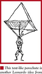
Leonardo even proposed an early parachute. His drawing of it states that if one owns a tent whose sides are 12 sajena in breath and width, one may safely jump from any height. The inventor’s manuscripts archived in Paris contain a sketch of a man
descending with the aid of a flat rectangular surface. Control is stated to be possible by tilting the surface. It is likely that the idea came to Leonardo as he watched sheets of paper fall.

In Leonardo’s day, science and craft had not advanced sufficiently to attain the desired result of flight. One man’s efforts, notwithstanding his genius, were insufficient to accomplish the required leap. Human progress follows its own logic. During the 17 th Century, Englishman Robert Hook and Italian Giovanni Borelli independently reached the conclusion that human strength on its own was insufficient to haul man aloft. Hook succeeded in building a working model of a powered ornithopter, but no documents survive to tell us what it looked like.
In 1643, Italian scientist Torricelli proved the existence of air pressure. Eleven years later, his discovery was confirmed by Otto von Gerricke, an inventor of gauges.
The latter undertook a rather impressive experiment. The air was drawn from a smallish sphere comprising two equal parts. Then each hemisphere was harnessed to eight pairs of horses which tried to separate them: an impossible task.
This led von Gerricke to conclude that similar lightweight spheres filled with rarefied air might be able to fly.
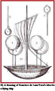
Developing von Gerricke’s conclusions, Italian researcher Francisco de Lana Torzi published a treatment describing an aerial ship. This consisted of a boat with sails, 1485
to which were attached four vacuum balloons. Torzi claimed such a device might launch rockets to scupper enemy ships or raze enemy cities. From that moment onward the idea of using the air in battle was no longer new. Torzi’s project was unfeasible: the materials available would either have made the spheres too weak to withstand atmospheric pressure as the air was drawn out, or would have been so heavy that flight would have been unthinkable. Ideas of similar apparatus reappeared in the early 20th Century as aluminium alloys became available.

 Dutch scientist and mechanic Cristiaan Huigens (1629—1695) left a wealth of papers. One of his inventions was a pilotless drone with two airscrews spinning in opposing directions and powered by twisted and stretched animal tendons: a prototype of today’s bungee chord-powered flying models. The wings were rectangular and had upturned tips for lateral stability. Hui – gens’ airscrews were the first proposal to use blades for motive power in the air. Their prototypes must have been the innumerable Dutch windmills, which Huigens is known to have studied over an extended period. No record suggests that this drone was ever built and flown, yet the drawing alone is evidence that Huigens overtook developments by over a century.
Bernouli’s classical work on hydrodynamics appeared in 1738. In it, the Swiss scholar laid the basis of today’s gas dynamics by clothing the theory of gas kinematics into mathematics.
Scientists were not alone in showing the way to flight. In 1742, the Marquis de Bac-
—————————————— >——————————————–
queville decided to cross the Seine by air. Having strapped wings to his arms and legs, the sixty-year-old jumped into uncertainty from the roof of a tall Paris hotel. Before the gaze of numerous onlookers, he managed to cover the great distance across the river before falling into a boat moored off the opposite bank. The feat is commemorated in many engravings, and a detailed description of the event survives.
In order to measure air temperatures a thousand metres above the ground, Alexander Wilson from the University of Glasgow attached a thermometer to the tether rope of a kite in 1749. Three years later, statesman and philosopher Benjamin Franklin barely avoided electrocution while studying the nature of lightning with the aid of a kite.
While researching meteorology and gas physics, Russian scientist and researcher Lomonosov also pondered how to elevate measuring apparatus to a great height. At an Academy of Sciences meeting on 4 February 1754, he delivered a general description of an Aerodynamic Machine based on Leonardo’s helicopter. Later that year, Lomonosov delivered an account of experiments with the Machine before the Academic Council. Sadly, the experiment had been a failure. For the next half-century, attempts to build heavier-than-air flying devices were confined to small-scale devices more reminiscent of toys than businesslike machines.
The separation of hydrogen, and the devising of a process for its production in quantity by Henry Cavendish in 1766, marked a leap in human attempts to shake off the bounds of Earth. The discovery drew the attention of scholars on both sides of the
|
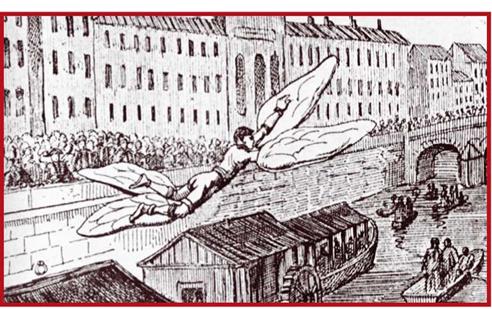
I Marquis Bacqueville overflying the Seine
|
Channel. A decade later, chemist Joseph Priestley published a number of experiments from research with gases.
These efforts gave a powerful impetus to the creation of lighter-than-air flying apparatus. However, the first ascent of a balloon took place far from Europe, and independent of European discoveries. Vanconne, a French missionary in China, came across a document dating back to 1624 in the Peking State Military Archives. This described how, during the celebrations marking the accession of Emperor Fo King in 1306, a hot-air balloon had been launched into the air. The event had remained unknown in far-off Europe, and the chance finding of its written record had no influence there: however, the natural progression of events did follow its logic.
French paper manufacturer Joseph Montgolfiere who lived and worked in An – onis, 55km south-west of Lyons, was one of Priestley’s readers. In 1782, he embarked on a series of experiments with balloons, all making use of the known fact that air is lighter when heated. He burned organic materials to obtain volatile gases, and conducted the first trials indoors, using small balloons made of thin silk. Filled with hot air obtained from burning paper, these floated to the ceiling. Later, Joseph successfully tested a balloon with a diameter of 3.5m, which he had made with the help of his brother Etienne.
Encouraged, the brothers embarked on making an 11.4m diameter sphere which they believed would be able to haul a man aloft. The balloon was made of paper-covered broadcloth. The official demonstration on 5 June 1783 was a great success. After the

|
I Etienne Montgolfier, 1745-1799
|
|
|
I Josef Montgolfier,
1740-1810
|
|

|
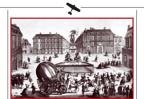
I Professor Charles’s first balloon goes through Paris escorted by guards
|
balloon was duly filled with hot air, its guy ropes were cut and the vessel rose aloft. On reaching a height of 2000m, it descended two kilometres from the place of ascent. The Mongolfieres sent an official record of the event to the Paris Academie des Sciences.
This achievement by a non-scientist was a challenge to metropolitan scholars, who felt slighted by a provincial backwater taking the lead. An appeal quickly raised 10,000 francs. By resolution of the Academie, Parisian scholars turned to 37-year-old Physics professor Jacques-Alexandre Charles. The young scientist took up the challenge with verve. Hiring the artisan brothers Robert as assistants, he ordered them to make a sphere of fine taffeta with a rubber backing, a diameter of four metres, and a volume of 33.5cu m. He decided to fill this with the newly discovered gas, hydrogen, which is 14 times lighter than air. Preparations for the filling began on 23 August. An enormous crowd gathered to watch. Three days later, filling was pronounced satisfactory to lift the balloon to a height of 30 to 35m. Held down by ropes, the flying machine passed triumphantly through the streets of Paris to the Champs de Mars escorted by mounted guards. The ascent was set for 27 August. After a 45-minute flight, the balloon landed near a village 25km from Paris. Taking it for a monster, the locals there had it dismembered into small pieces in a matter of minutes.
After an unsuccessful ascent attempt on 19 September, the Montgolfieres organised a demonstration before the Royal Family at Versailles. The balloon had a 13.5m diameter and a volume of almost 1300 cu m. The ascent was to a height of just 600m, the flight
|
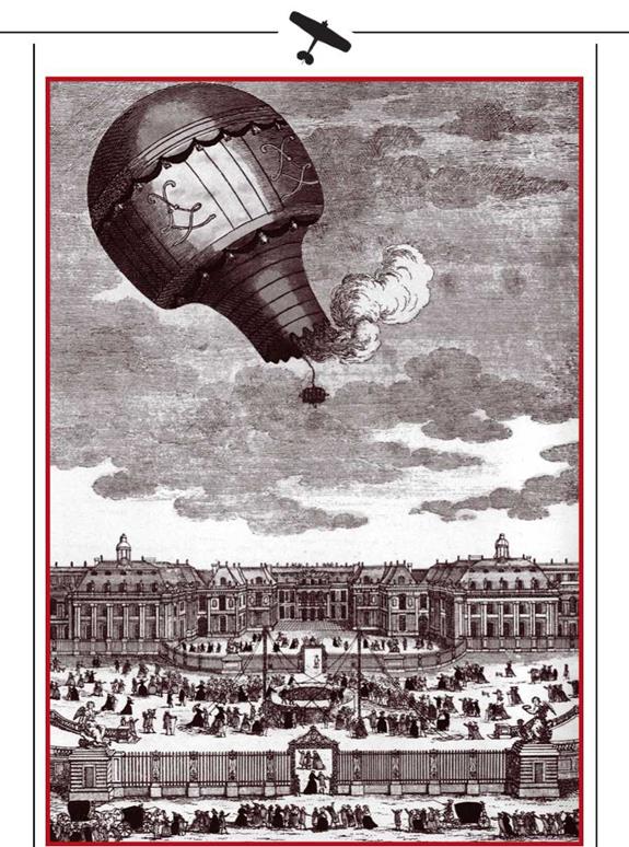
The Montgolfier brothers’ demonstration before the Royal Family at Versailles
|
|
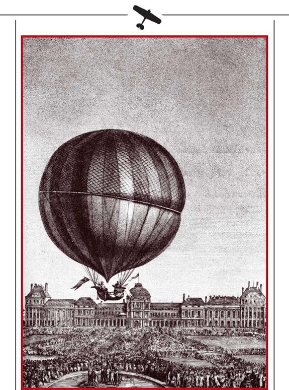
I The first ascent of a hydrogen-filled balloon on 1 December 1783
|
 lasting eight minutes. After a soft landing four kilometres from the Royal stand, the pioneering Aeronauts were recovered safe. Louis XVI and Queen Marie-Antoinette were impressed and congratulated the Montgolfieres on their success.
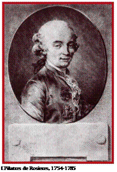
Observers of the Versailles demonstration included 26-year-old physicist Pilatres de Ro – sieres. He was later to devise a tethered balloon and accomplish several test ascents during which he took additional fuel into the gondola. He proved that ascent and descent could be controlled by the rate of combustion. On 21 November 1783, Rosieres and the Marquis d’Arland were the first to make a free flight in a man-made apparatus. This had the impressive size of 14m diameter and over 1400m3 volume, and enabled eight kilometres to be covered in 25 minutes.
A hydrogen balloon departed the Tuilleries on 1 December 1783, carrying Professor Charles and the elder of the Robert brothers. Having flown for two hours at a height of 650m and covered 40km, they descended to a soft landing by dumping part of the hydrogen through a specially designed valve. Robert stayed on the ground, while Charles ascended to 3500m.
French success did not remain unnoticed elsewhere in Europe. In February 1784, Paolo Andreanni of Milan accomplished the first Italian flight in a hot-air balloon alongside the two artisans who made the balloon. The flight lasted 20 minutes. Seven months later Vicenzo Lunardi de Lucca, a clerk at the Neapolitan Embassy to London, ascended from the Honourable Artillery Company’s grounds in Moorfields in a hydrogen-filled balloon, accompanied by a dog, a cat, and a pigeon. He flew for 33km, attempting to control flight altitude and direction by means of paddle-like surfaces.
The title of first British aeronaut, more for courage than achievement, goes to James Titler of Edinburgh. In the late summer of 1784, he employed a crude balloon and the properties of hot air to make a couple of brief hops into the air. The first such hop was on 25 August: three weeks prior to Lunardi’s historic flight. The second and last hop was on 1 September. However, the pioneer British aeronaut in the proper sense was James Se – dler. His first ascent was on 4 October 1784, when he covered the distance between Oxford and Islip in a hot-air-balloon. His next flight was on 12 November. On that occasion he used hydrogen to fill the balloon, hoping for a more notable result. And
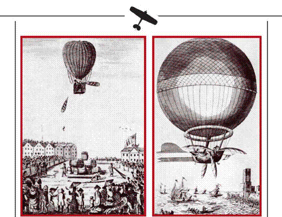
indeed, the change proved justified: he covered the 23km from Oxford to Hartwell in 17 minutes. In 1785 Sedler made five flights which included an 80km flight. He then gave up ballooning for 25 years.
Other feats, which made aeronautics something of a craze rather than a risky pursuit, included the ascents of Francois Blanchard. If we exclude Lunardi, Blanchard was the first professional aeronaut. Accompanied by anatomist John Shelton in a hydrogen- filled balloon, on 16 October 1784 Blanchard covered the 115km from Chelsea to Ramsay in Hampshire. Success drove the Frenchman undertake a risky attempt to fly the Channel. The epic 12-hour flight took place on 7 January 1785, in the company of American Doctor John Geoffrey: financier of the attempt determined to convince himself that the aeronaut would not cheat. Between 1785 and 1789, Blanchard made a series of demonstration flights in various European countries, using hydrogen more often than hot air. He set a 480km distance record with the aid of air currents.
After the start of the French Revolution, Blanchard was accused of anti monarchist propaganda in Austria and was arrested there but managed to flee to the USA. There on 9 January 1793 he performed the first ascent in America. This was in Philadelphia, using a hydrogen filled balloon. Returning to France in 1798, he resumed receiving the
 pension awarded him by Jouis XVI on the occasion of overflying the Channel.
This exceptional man died of a heart attack in 1809 after his 60 th ascent.
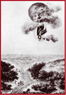
Aeronautics claimed its first victim all too soon. Two years after his first ascent, Pilatres de Rosieres perished while attempting to fly the Channel, taking with him co-traveller Pierre Romain.
Before Englishman Charles Green used lighting gas in a balloon, a serious drawback of hydrogen was the considerable time and effort expended in filling balloons. Hydrogen could not be generated in flight; ascents could only be made where the heavy process plant and none too widely available materials could be procured. On the other hand, hot-air balloons needed nothing more than matches, readily available fuel, and a furnace box. However, they had limited endur – ■ The death of Pilatres de Rosieres ance and payload. In both cases, aeronauts were at the mercy of wind speed and direction: Lunardi’s and Blanchard’s guidance devices were of no help at all. Balloons strictly followed the wind. A dirigible could not have been built in the late 18th Century due to the lack of any suitable powerplant.
The above account forms the background to the formation of the first component of nascent air power: the invention of a sufficient number of reliable flying machines. Initially, balloons were used for research; but the issue of their other uses arose soon enough. Charles’s Flying Sphere made him ponder possible applications. Seeing far beyond the 4m diameter sphere, the Professor stressed balloons’ military promise in letters to friends in Philadelphia, London, and Vienna.
Data on enemy positions, movements and actions on the battlefield and beyond were considered the key to military success. The use of spies and informers always put their lives at risk. The cavalry was trained for rapid raids around the field of battle, partly to discover enemy locations. Invariably, the purpose was to determine the status of the other side: to ‘look over the hill’ or over the horizon, so to speak. And even while still primitive, balloons were ideal for this purpose.
In 1794, an anonymous French author published a monograph, LArt de Guerre change par l’Usage de Machines Aerostatiques. This early study of the significance of
balloons in combat claimed that they could lead to a sea change in the art of war. In the early 1790s, the eminent chemist Guiton de Morveaux laid down the basics of aerial reconnaissance by tethered balloon. French Army officer Meunier, a capable engineer and physicist, presented a paper describing gas balloons’ safety and stability before the Academie des Sciences. He went on to make a spherical balloon with the basic propelling and controlling devices of an elevator and three large propellers. Meunier’s remarkable project embodied all achievements up to that moment. Its major disadvantage was the lack of an engine: in its absence, the designer had to rely upon the combined muscle power of the balloon’s occupants.
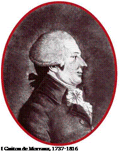 France became embroiled in Revolution and the war against Austria. Meunier was killed near Meinz in 1793. On 14 July the same year, a Convent session approved the use of balloons for military purposes. Means and premises for war balloon production were set aside, with the proviso that sulphur oxide, vital to the artillery, was not to be diverted for hydrogen production. An officer, Jean Coutelle, was put in charge of testing. He managed the task of obtaining large amounts of hydrogen in field conditions brilliantly. The first installation was built near Meudon. Meanwhile, an elastic varnish had been discovered to seal balloons against gas leakage, treated balloons maintaining their shape for two to three months. Tests of the LEntreprenant combat balloon intended for quantity production ended successfully, and in April 1794 the basis of the eventual planned Balloon Division was laid. Initially, it comprised a single Balloon Company. To try out the Eyes in the Sky concept in combat, the Convent ordered Captain Coutelle to Belgium at the disposal of General Jourdain. The latter, and the majority of officers viewed the new arrival with incredulity.
On 2 June 1794, Capt Coutelle took his place in the gondola along with his assistant and gave orders for ascent. Two groups of soldiers, each 32-strong, began releasing the guy ropes. Soon the aeronauts were a thousand feet up and began history’s first aerial reconnaissance, comparing their maps with the battlefield they surveyed.
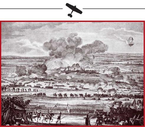
When the Battle of Mobeuge began two days later, General Jourdain’s Adjutant Morleaux was in the gondola alongside Coutelle. Over the next eight hours, the two sent a stream of messages regarding the rapidly evolving situation. The battle was won with the active help of the aerial observers.
|
I The Battle of Mobeauges: the use of an airborne vehcle in warfare becomes fact
|
Regardless of the heavy intallations, some of them stationary and having to be built in situ, the balloon was shown to be a reasonably effective means of observing and directing artillery fire. General Jourdain’s command sent apologies for its initial doubts. A new order sent the Balloon Company to the aid of French troops near Fleurix, some 20km distant from its camp.
The journey turned out fraught. The balloon was transported erect, tethered at a height sufficient to clear roof tops. Coal dust smokescreens masked its progress. Fifteen hours after it had set off, the unit was ready for action.
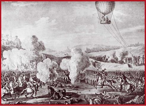
The French Army faced difficulties. After heavy battles for control of Charleroi, Gen Jourdain split the 73,000 men under his command into three, posting them west, north-east and north of the city with the order to defend it. The approaching Allied Army was of approximately the same size, but its commander, Prince Ferdinand of Saxe-Coburg-Gotha, made a fateful error at the outset. He split the attackers five ways and set seven directions of advance. The tactic was not unusual in its day, but the Austrian noble had no inkling of the new French way of getting reconnaissance.
On 29 June 1794, Gen Jourdain himself is likely to have been in the gondola along with Capt Coutelle. The two men witnessed an impressive sight. Camouflage and deception were arts that would develop over a century later (indeed, a reason for their late
development was the prior lack of means to observe armies from the air!). Allied units in bright, elaborate uniforms, made not the slightest effort to hide their thrust towards French positions. Each infantry regiment had its own distinctive wear. All this eased the French command’s orientation in the course of battle, and helped it adopt correct decisions.
Coutelle would observe the battlefield through a telescope and apply his findings to a map. Individual units’ bright colouring clearly delineated infantry from ulans, Dragoons and other armed units. The first aerial spy determined cavalry and artillery strengths rather precisely, pinpointed the site of the Austrian Command, and noted backup units arriving from up to 60km off. Several-hour long sojourns in the air were by now routine. Coutelle would periodically tie his information to bags of sand, and would lower it to the ground by long lengths of string. Thus, according to researcher Hodgston, “the information sent as signals to Gen Jourdain was a proven material factor in securing French victory over the Allies.”
The Battle of Fleriux was the first in human history in which an air unit was employed in a planned and purposeful fashion. The result was a practical example of the benefits the new environment bestows. Following the brilliant despatches regarding the activity of the Balloon Company, preparations for forming a second such Company started as early as 23 June. By late summer, four balloons were in active service,
|
Щ The Battle of Flerius
|
each with ground equipment, aeronauts, and backup crews. They helped achieve victory at Urtes near Liege and reconnoitred at Augsburg, Stuttgart, Vorzburg, and Donauworth, providing valuable information on enemy movements.
However, enthusiasm was short lived. After successful operation in Europe, Capt Coutelle’s Balloon Company accompanied Napoleon to Egypt in 1798. Before the unit could unload its equipment at Abukir near Alexandria, Counter-Admiral Nelson’s main British fleet appeared. The battle of 1 August reversed plans for the conquest of Egypt, and the Balloon Company’s property was completely destroyed.
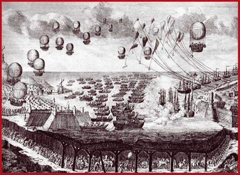
Upon returning to France the following year, Napoleon disbanded the Aeronautical Division. The testing and training establishment at Meudon also closed. On the one hand, this could be seen as an expression of the young Emperor’s vain belief in his infallible ability to divine enemy locations and intentions. On the other, the decision was not devoid of some merit. The poor reliability of tethered spherical balloons, the arduous transportation of heavy equipment, and the lengthy gas filling cycle hampered the mobility of associated units, particularly artillery batteries, for whose benefit the balloons were supposed to act. Nevertheless, some Napoleonic Wars researchers claim that the availability of balloons might have saved the Emperor from defeat at Waterloo, changing the course of subsequent European history.
|
I An artist’s impression of Napoleon’s plans to invade Britain
|
|
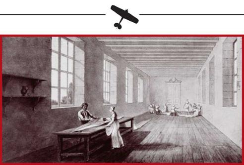
I The Meudon balloon manufacturing workshop
|
Barely emergent aeronautics had already influenced the art of war. Some of the componentry of air power, slated to become topical a century hence, was also in place. Despite its inherent lack of safety and stability, flying apparatus did exist, providing platforms for aerial reconnaissance. Also available was personnel, poorly trained though it was. Another component was the ballooning school, though service units lacked a proper method of training which took account of the specifics of warfare. Airborne and ground equipment was still rather primitive. Observation was through standard field telescopes which were rendered unusable by any stiffish wind at altitude. Thus gondola crews did little more than look out onto the battlefield, albeit in some depth behind enemy lines. Backup means also emerged.
Limited finance delayed the creation of a manufacturing base, and ultimately the Emperor’s hasty decision destroyed what little had been achieved. There was no system to govern the actions of aeronauts, nor was there any systematic method of communication between officers on the ground and in the air. Information transfer methods were also primitive, as could be expected of the period. In certain situations this rendered balloons useless.
However, all this ought not to obscure the main point in any way. It was another six decades before military men were to return to the air: this alone shows French strategists’ forward thinking in battlefield assessment during the Revolution.
Pioneering attempts to overcome gravity with heavier-than-air apparatus date to about the same time. In 1784, Frenchmen Lenois and Bienvenue demonstrated a helicopter model in Paris. This had an elementary clockwork motor which transmitted power to lifting blades calculated to lift the model off the ground at a certain rotational
|
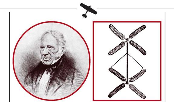
I John Cayley, 1773-1857 ш A drawing of Cayleyfs helicopter, 1796
|
speed. As in the case of Lomonosov thirty years prior, no documentary evidence on this test reaches us to enable an assessment of its contribution to aviation.
In 1796, Yorkshire Baronet and philanthropist Sir John Cayley combined his pecuniary means and remarkable engineering bent to create another working model of a helicopter. This was essentially identical with that of Lonois and Bienvenue. After some improvements, he demonstrated it in public, causing interest on both sides of the Channel. Money was raised by voluntary subscription and with it the Baronet set up a charity with the major purpose of creating a heavier-than-air flying machine.
Given the choice between lighter-than-air and heavier-than-air flying machines, almost all inventors bent on conquering the air focused on the former: it seemed that balloons would do the job more easily. Cayley was one of the few who stayed faithful to the idea of dynamic flight. It is to him that we owe the theory of flight with fixed wing aircraft. He viewed the motorised aeroplane as a kite whose towrope had been replaced by an engine, and formulated the real issues of powered flight: using the wing surface to create lift, and overcoming drag. The lack of suitable engines directed his attention to gliders. Cayley reached the conclusion that in them (excepting towed gliders) the resultant force of the structure plus a man or other load could overcome drag.
For his first attempt to test this contention, Cayley designed a boat-like flying machine with a wing square in plan and set high at a slight angle to its longitudinal axis. Tail surfaces provided longitudinal and lateral control. No evidence exists that a model was built or tested. However, despite its shortcomings, this represented a step forward to the creation of an aeroplane. For the first time, we have the basic components in place: fixed wing, fuselage, and empennage.
|

I A drawing of a typical early Cayley aeroplane model
|
Having gathered theoretical knowledge, by 1804 Cayley built history’s first freely flying model of a fixed wing flying machine. The wing has an area of 0.1sq m and six degrees’ fixed angle of incidence to the fuselage. The model had a cruciform empennage for control and trim. Testing proved that flight was possible with fixed wing apparatus, the glider covering distances from 18m to 27m at a speed of some 5m/sec.
Meanwhile, ballooning continued to be a pursuit for the wealthy, a trade for the reckless, and a wide-open field of research. A scientific flight was recorded in Russia on 30 June 1804. This was preceded by several Academy of Sciences’ sessions which discussed the programme and listed materials and gauges the researchers needed. The actual flight was held up to await the Tsar (who never arrived). The crew did finally fly at a quarter past seven in the evening, by when conditions were against them (at dusk the gas cools and its lifting power declines). Weather conditions limited the ascent to not more than 2000m. Nevertheless, the test programme was accomplished. It proved that altitude could be determined by echo sounding: directing sound at the earth’s surface, and measuring the time it took to reflect back up to the balloon. The crew stayed aloft for three and a half hours and landed 30 versts from Sankt Peterburg. Before landing they lowered a bundle of unnecessary items to the ground, this being the first guyrope in history.
In the second half of 1805, Staff Doctor Kashinskiy made a demonstration flight over Moscow. Prior to the event, his aerostat was displayed to curious Muscovites at the Grand Hall of the Petrine Theatre.
After Blanchard and Robertson’s successful flights over the Austrian capital, Vienna clockmaker Jakob Degan set off to make a controllable flying machine. He studied aeronautical literature in detail and paid particular attention to ornithopters. Using reed, oiled paper, silk thread and timber lathes, the structure he produced weighed just 14 kilos. Degan made several flight attempts and concluded that success required the attachment of his ornithopter to a hydrogen balloon. On 12 November 1808 he succeeded in staying airborne for some minutes before a huge crowd. There was a definite impression of control, since the apparatus alternately lifted, descended and moved sideways. The effect was astonishing. The Austrian Emperor awarded Degan 4000 guilders, and Austrian newspapermen spread the news that controllable flight had been achieved
|
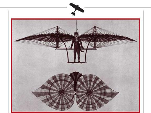
A contemporary drawing of Jakob Degan and his strange flying contraption
|
throughout the Old Continent. However, foreign newspapers sowed doubt as to the authenticity of the flight. To dispel them, Degan travelled to Paris in 1812.
On his first attempt on 10 June, he failed to become airborne. The same happened on his second attempt on 7 July, despite widespread reports that he flew but failed to manoeuvre as required. The third attempt took place on the Champs de Mars on 5 October, and was also a failure. The angry crowd attacked the ‘prestidigita – teur,’ reducing his apparatus to pieces. The papers declared Degan a charlatan and soon the name of this industrious and intelligent man was forgotten even in his homeland.
On 17 July 1817, Whitham Sedler, younger son of James Sedler, crossed the Irish sea from Dublin to Anglesea by hydrogen filled balloon in five hours. In 1836, Charles Green broke all distance and endurance records in ballooning in the company of two fellow travellers. In 18 hours he covered the 800km from London to Wilburg near Frankfurt. He filled his balloon with lighting gas which offered less than half of hydrogen’s lift but was cheaper and more easily produced.
Three years after Green’s remarkable flight, American aeronaut John Weiss designed and fitted a special rapid gas discharge flap to a balloon, enabling rapid descent in emergency. His invention significantly improved safety and subsequently became standard. Weiss’s successes did not end there. In 1859, accompanied by John la Mautin (‘Gegard’)
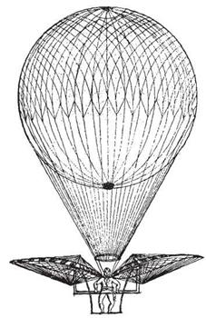
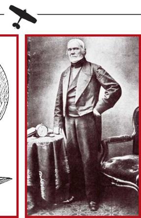
I The later version of Jakob Degan’s flying machine Щ Charles Green, 1785-1870
and a newspaperman, he flew the 1300km form Saint Louis, Missouri to Henderson. Encouraged by this, the trio decided to beat their own record and fly the Atlantic using their proven balloon. However, the idea remained in the realm of intentions.
Their major competitor was another American professional aeronaut, Thaddeus Loewy. Also aiming to conquer the ocean, he had designed a balloon with an even larger volume. A sudden whirlwind an hour and a half prior to departure put an end to the flight by destroying the balloon which was being filled at the time.
Meanwhile, Cayley had accumulated much knowledge and experience in heavi – er-than-air flying machines. One of his greatest achievements was to conceive the first multi-plane flying machine. In 1849, forty years after his first fixed wing aircraft, he assembled a triplane with auxiliary manually activated flapping surfaces. Cayley’s rationale in adopting a multiple wing consisting of three surfaces one beneath the other was to reduce span (and hence weight), while keeping wing area (and hence lift) unchanged. The Baronet’s coach driver and a ten-year-old boy tested the machine: pulling it downhill or into wind, they attempted to get airborne. Sadly the best results were counted in metres: wing aspect ratio was insufficient, and the three wings were too close to each other, resulting in poor lift.
|
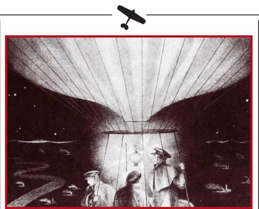
I In his historic 1836 ascent, Charles Green flew a distance of 800km
|
|
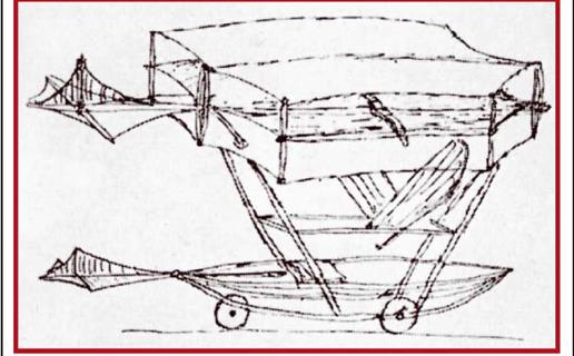
Щ A sketch of Cayley’s triplane
|
Cayley followed this up with a series of gliders in which he incrementally improved various elements, reducing drag and improving stability. In 1853, the last of these flew 60m. Over almost half a century the Baronet published a number of papers, some giving ‘masterclasses’ on the principles of flight aerodynamics and controllability, and others dealing with emergency escapes from balloons using aerodynamically stable gliders. These caused much interest and their ideas found adherents.
One such adherent was William Samuel Hanson, manufacturer of rope and lace making machines. In 1843 he registered a patent for an Aerial Steam Car for the transportation of mail, goods and persons by air. Though never built, the project marked an important step forward in aviation. It was the first design to envisage all basic elements of propeller aeroplanes of a century hence, and was the first aircraft to capture the mass imagination. No book on the history of aviation is complete without a mention of this exceptional machine. It was a high wing monoplane with two six-bladed pusher propellers. The fuselage was completely faired and contained the steam engine, fuel, and room for freight and the crew. The Steam Car had elevators and rudder, and wheeled landing gear. Takeoff was to be accomplished along a downward sloping surface. To reduce the weight of the powerplant (a 25/ 30hp steam engine), the designer replaced the usual steam boiler by a series of cone-shaped vessels and air condensers. Calculated gross weight was some 1350 kilos, wing area was 420sq m, and the empennage measured 140sq m. The design’s most significant advance was the choice of motive power: flapping surfaces were abandoned and propellers proposed.
Hanson’s Steam Car was never built, but drawings and artist’s impressions of it travelled the world, begetting much discussion. Decades later, aeroplanes with an
|
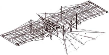
An axonometric cutaway of Hanson’s Steam Car taken from its patent licence
|
|
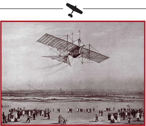
I An artist’s impression of Hanson’s Steam Car in flight
|
identical configuration (but with engines using a completely different working principle and having significantly greater relative power) would take over human attempts to conquer the air.
On concluding his project, Hanson and his friend Stringfellow built the first model aeroplanes. The third such scale prototype was built almost entirely by Stringfellow due to Hanson’s leaving for the America. All models looked like the Aerial Steam Car and had miniature steam engines. The largest weighed 12kg and had a span of 6.7m. Insufficient power rendered them unable to perform genuine flights.
Early work on heavier-than-air flying machines did not attract visible military interest. During the half century from the French Revolution and the first use of airborne apparatus, only British Admiral Knowles suggested the use of tethered balloons for Navy needs. British conservatism had the final word and the idea was rejected.
Austrian troops suppressing the 1849 Italian Risorgimento against the Habsburg Empire fought long and hard against the defenders of Venice. The lagoon city was invulnerable to artillery fire from dry land, so the command of the besieging army decided to use airborne devices in a novel way: to bombard the city form the air. Their 82 m3 hot-air balloons were made of non-porous paper. Below the ventral aperture was a ring to which were attached 15kg explosive and incendiary bombs.
|
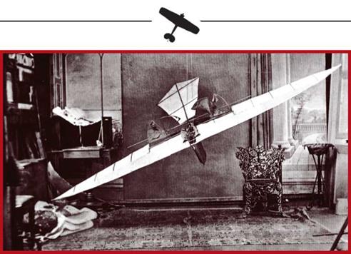
I Photograph of one of Stringfellow’s aeroplane models from the late 1840s
|
Dropping and activation times were governed by the length of fuse which was lighted a short time prior to the start of ascent. Each bombing run was preceded by a trial ascent to determine wing speed and direction. A launch site was then chosen and flight time to overhead the target (and hence the length of fuse needed) was calculated. The average launch time was almost six minutes. The idea was to make some 200 sorties, each lasting about half an hour. A hundred balloons were produced, but despite the idea’s originality, it did not work well in practice. This was due to the poor selection of launch sites, changes in wind direction and speed, and a variety of other reasons. Those balloons that did reach their targets caused only slight damage. However, by mere fluke one such bomb landed right in the city centre, on the Piazza San Marco, and showed that even ineffective aerial bombardment could visit much distress upon the public.
During Napoleon Ill’s 1859 Italian Campaign, the French army tried hot air balloons for field reconnaissance, but their shortcomings limited endurance and they were not used in combat.
|

Щ Drawing of Pierre Julien’s dirigible
|
|
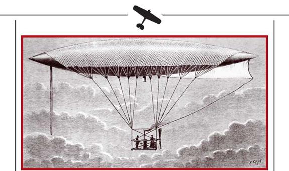
I Drawing of Henri Gifard’s dirigible in flight; note the gondola and the net by which it is suspended from the balloon body
|
Controllability was proving an insuperable problem. Powerplant progress was rapid from 1850 onwards. French clockmaker Pierre Julien demonstrated an aerodynamic model of an airship driven by two propellers actuated by a clockwork engine.
Public acclaim for the model made talented engineer and inventor Henri Gifard design a controlled lighter-than-air flying machine. This was driven by an enormous propeller actuated by a 3hp steam engine. Powerplant weight, including the steam accumulator, came to some 150kg. The balloon body was faired so as to be longitudinally symmetrical, with pointed ends. For safety, the crew, engine, fuel and ballast were housed in a gondola hanging some 13.5m below the balloon on rope rigging. The exhaust stack was pointed downward and to the rear, directing sparks away from inflammable items.
Etienne Lenois’s 1860 invention of a gas engine opened new possibilities before aviation and aeronautics. Five years later Austrian Paul Henlein patented the installation of a gas engine in a dirigible, but another seven years would elapse before the project was realised.
The 1861 to 1865 American Civil War saw leading US aeronauts offering their services to the North. John Weiss designed a field hydrogen generator. However, its high cost made it practically unaffordable and the military did not finance the project. Instead they opted for an idea proposed by Thadeus Loewy. Twelve of his generators were manufactured and entered service. Feedstocks included sulphur oxide and metal swarf. The device could fill an observation balloon in under three hours. Though rather heavy and difficult to transport, the lack of any alternative made the generators indispensable until the end of active aeronaut duty.

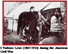 Another original idea of Loewy’s was to employ river barges as mobile bases for tethered balloons. To assist nocturnal missions, each barge had four navigation lights: iron lamps with their own uninterrupted gas supply. The newly invented telegraph was intended to be used to transmit observation data to the ground. This was first tested in the air on 24 September 1861 at the Battle of Falls Church. To facilitate data simultaneous transmission from several balloons close to one another, one was designated as an airborne base to gather, process and retransmit data. Another innovation in aerial reconnaissance was aerial photography, first practised by Frenchman Felix Nadar in 1858. All this gradually went to construct two basic control effectiveness components of air power: on-board and surface equipment.
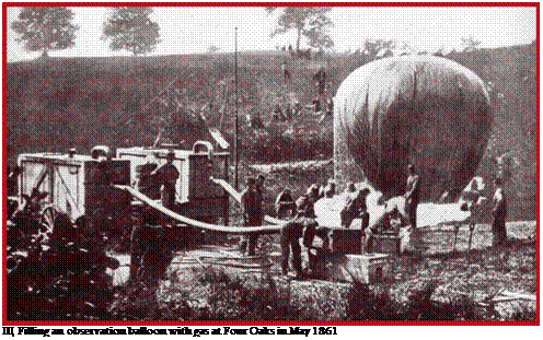
By late 1862, the North had seven tethered balloons with an overall volume of 450-900m3. They were purpose built for combat, usually operating at some 1500m altitude. John La Montaigne was the most active aeronaut. Making use of prevailing winds at altitude, he made several free flights over Confederate positions. The balloon corps gained great confidence in senior Washington, D. C. circles, particularly after it saved Federal forces from defeat at Four Oaks and Gaines Mill. In both cases,
|
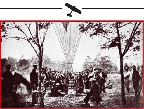
Preparations for the first flight of an airborne telegraphic device: Falls Church, September 1861
|
balloonists had delivered timely warnings of enemy breaches of Federal flanks. However, aeronauts turned out a wayward bunch. Aiming for personal recognition, they were in constant conflict with each other. The authorities had erred in not giving them officer commissions and in leaving them outside army structures, unbound by military discipline.
Making the best of limited finance, the Confederacy adopted simple yet effective countermeasures: the blackout, and luminary mimicry. For the first time in history, all lamps and fires were doused upon a signal at dusk, while false encampments were plentifully illuminated. Apart from that, the South also attempted to employ balloons, John Randolph Brien making several flights at the start of hostilities. His poorly designed hot-air balloon with limited endurance was duly replaced by one filled with lighting gas and made from a patchwork of multicoloured silk pieces. (Thus arose the legend that the women of Richmond, Virginia, had sacrificed their dresses for the cause.) The original ‘silk dress’ balloon was captured by Federal forces at Turkey Bend in 1862. The Confederacy then put a similar balloon into service, this seeing active service for 12 months before being blown across the lines by a gust of wind, and also turning into a trophy (though without an aeronaut on board).
There had not been a qualitative leap in the combat use of flying machines since the French Revolution, but Loewy’s achievements in America impressed military observers. Some of the latter were to leave a trace in the history of aviation. Young German Army officer graf von Zeppelin was one. What he witnessed gave him the
>
|
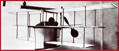
I Stringfellow’s triplane
|
idea to which he would dedicate his entire subsequent life. Another was British military observer Captain Beaumont. Upon returning to England, he and Capt Grover tried to draw War Office attention to the possibility of using airborne devices in combat. They flew two demonstrations using a balloon hired from Henry Coswell, Britain’s best aeronaut at the time. Grover went on to fund a military balloon programme at his own expense; fifteen years would pass before it attracted genuine interest.
After twenty years of none too successful work on gliders, and influenced by the hostile comments Cayley and Hanson’s monoplanes drew, Stringfellow looked at multiplanes. At the Crystal Palace Aeronautics Exhibition, he showed a triplane model which looked rather archaic by comparison with his 1848 monoplanes.
This had three flat profile superimposed wings braced by vertical struts. It was powered by a 0.33hp steam engine located in a fairing beneath the lower and middle wings, and actuating two pusher propellers. Span was 2m, and weight: 5.4 kg. Due to fire precautions, Exhibition organisers prohibited flying, with demonstrations limited to runs along a guide wire. Subsequent open air testing was unsuccessful, the onrush of air extinguishing the jet of burning spirit which heated the boiler.
Despite this, Stringfellow’s triplane marked an advance in multiplane design and was influential in the choice the Wright Brothers were to make.
Another inventor who made quality aeroplane models was Alphonse Pennault. The son of a French Admiral, he improved on Pierre Julien’s invention of elastic to power flying models. Where Julien used a flat band of elastic, Pennault used twisted bungee, thus obviating the need for transmission between unravelling elastic and spinning propeller, and lightening and simplifying things. Alongside this, Pennault paid much heed to stability. In 1870, he created a most successful helicopter model. A year later came the tiny Planophore monoplane which had great stability in all three axes. In pitch, this was granted by aft horisontal tail surfaces, and in roll: by vertical
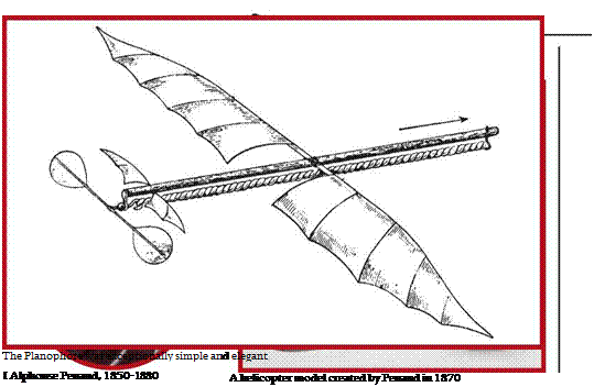 |
endplates and a fin. The Planophore was extraordinarily simple. Just 0.5m long, it had approximately the same span, and weighed just 16g, 5.5g of which was the bungee cord. Tested on 18 August 1871 in Paris, the model demonstrated exceptionally stable flight, always ending with soft landings. The maximum distances of some 40m to 50m were covered in 11 to 13 seconds.

This fragile toy represented an exceptional event in the story of aviation. For the first time the public could observe feasible flight in a device that was heavier than air, had a fixed wing, and used its own power. Reports of the flights circled the globe, stimulating numerous enthusiasts.
By the mid-1870s France alone had several similar aeroplane models. Later, elastic-powered aeroplanes appeared in Russia, England, and Austria. The fact that modern elastic-powered aeroplane models do not differ significantly from the Planophore is a testament to its advanced design. Pennault was also the first model maker to pay heed to commerce. Selling at reasonable prices, his models brought the invention into many households.
While aviation was still at the model aeroplane stage, aeronautics enjoyed a new renaissance. At the outbreak of the 1870-1871 Franco-Prussian War, Prussian forces possessed two balloons which were not used in combat. After the fall of Sedan, the French made several observation and reconnaissance ascents in tethered balloons. Privately owned and designed for free flight, they were unsuited to this task.
Attention to flying machines picked up quickly after the Prussians surrounded Paris. The besieged garrison badly needed to communicate with the high command and government in Tours. At the instigation of several aeronauts, the postal authorities set up a balloon mail. An improvised balloon factory was established on the premises of a redundant railway station, employing seamstresses and seamen. From September 1870 to January 1871, 66 balloons left Paris, carrying over ten tonnes of mail, 160 privileged persons, several hundred pigeons, and five dogs. These balloons also threw propaganda over enemy positions. Over 60 of the pigeons returned to the city with messages, and some flew the trip twice. However, though sent out with similar intentions and fitted with special collars, the dogs failed to return.
To systematise the knowledge acquired, in 1874 the French Government established an Aerial Communications Council. This recommended the reestablishment of the Military Aeronautics Institute on its old Meudon site. Following this example,
|

I Preparations for the raising of a spherical balloon, Paris, 1870
|
Britain, Italy, Germany, and Russia also set up aeronautics schools and research establishments between 1878 and 1893. The USA also systematised its experience of aeronautics, albeit with a thirty year delay. Due to the low technological level of flying apparatus, no combat units could be formed yet.
Even after the Franco-Prussian War, the main problem of aeronauts remained that of control. Development continued to be hampered by the lack of suitable engines. However, research continued. A large dirigible commissioned by the French government was completed on 2 February 1872. Designed by Naval Engineer Henri Dupuis de Loms, it did not feature an engine but was driven by a large four-bladed propeller driven by eight men turning a crankshaft. Still air speed was comparable with that attained by Gifard. However, reaching it required such physical exertion that the test was not deemed successful.
Ready for testing in 1872, Paul Henlein’s dirigible had an engine which drew gas from the balloon. Catamaran shaped, it was 55m long. Flights took place on 13 and 14 December. Hard to control, the craft needed to be accompanied by troops in case of difficulties for the crew. A speed of 15km/h was reached but further testing did not take place due to the lack of funds. The craft was dismembered and sold at auction.
Charles Ritchell’s single seat balloon was tested near Hartford, Connecticutt, in 1878. Powered by a pedal-driven propeller, it was 27m long. Flying a closed circuit, Ritchell attained a speed of 5.7km/h.
|
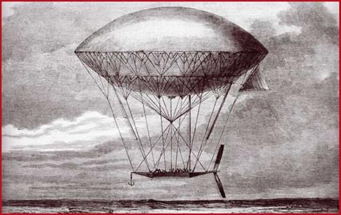
Artist’s impression of Henri Dupuis de Loms’s airship
|
|
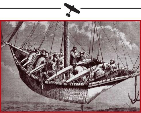
Щ Arduous labour in the airship’s gondola
|
During the 1881 Electrical Exhibition in Paris, brothers Gaston and Albert Tes – sandiere caused great interest with their model of an electrically-powered airship. The designers decided to build a full scale version capable of accommodating a man. As distinct from Gifard’s design, this airship had greater volume and rounder shape. A propeller driven by a 1.5hp Siemens electric motor powered it. Since the batteries alone weighed more than the combined weight of a steam engine and steam tank, the craft attained just half its design speed.
The airship designed in 1884 by French military engineers Charles Ronard and Arthur Krebs had more powerful electric motors. Similar to Henlein’s, it differed in being half a metre longer. Initially fitted with a 7.5hp motor, it was later fitted with one rated at 8.5hp. Flying seven times in two years, it reached a maximum still air speed of 24km/h. All but two of the flights ended on the spot where they began. The powerplant did bestow control, but only in essentially still air.
Again in 1884, a steel cylinder containing hydrogen under pressure was designed in Britain. This granted much greater mobility to emergent military balloon units. Thanks to this, a three-balloon Royal Engineers detachment participated in the military expedition to Bechuanaland (today’s Botswana). A year later, the British actively used balloons in the Eastern Sudan, followed by the Italians in Eritrea in 1887 and ’88. However, balloon combat efficiency in the late 1800s was not that much higher than it had been during the French Revolution. Despite greater mobility, balloons
|
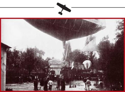
Tessandiere’s electric-engined airship was Siemens-powered
|
|
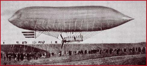
I Henlein’s airship
|
remained unstable and at the mercy of numerous circumstances. Despite early combat experience, not one of the components of air power was yet firmly in place.
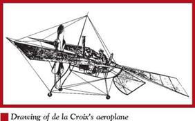
A decade after Stringfellow’s first model tests, French naval officer Felix de Temple de la Croix and his brother Louis built a clockwork-powered aeroplane. This achieved record success, being able to take off, fly, and land. Later, the clockwork was replaced by a steam engine. In 1857, de la Croix was granted a patent for a propeller driven monoplane. The design featured several impressive and advanced ideas. Made largely of aluminium, it had an unencumbered wing and a damped-strut retractable undercarriage.
After model tests, the inventor began building the full sized model, intending to fly it. Construction took until 1874. Practical limitations imposed some simplifications: the landing gear was fixed, and the wing had a single spar instead of the intended two. Despite this, the 260kg structure weight was over twice what had been predicted.
The aeroplane was a steam-engined monoplane with a six bladed propeller. The open-topped fuselage was 2.5m long and 0.8m wide. Its welded steel tube structure also carried the wing, tail surfaces and tricycle undercarriage.
Weighing 59kg and developing 3 to 4hp, the steam engine was located forward. The boiler was superheated with fuel oil, with the fuselage structural tubing used to condense the used steam. The pilot sat behind the engine. Wing structural elements were steel tubes. Cloth-covered, the wing spanned almost 30m. Of similar structure, the empennage comprised movable horizontal and vertical surfaces. The stalky undercarriage gave a ground run incidence of some 20-25 degrees.
Ground tests showed insufficient structural strength. Lack of money forced Felix de la Temple de la Croix to curtail further development. Even though not one attempt to take off was made, the designer deserved due recognition. He was the first to progress the idea of heavier-than-air manned flight from scale models to a practical full sized aeroplane which he had every intention of flying. In this sense, de la Croix’s achievement marked a stage in aviation research.
The lack of development in engines during the late 1860s and early 1870s, combined with a lack of clarity and an absence of scientific and financial assistance, doomed the efforts of a generation of designers such as Evard (Russia, 1861), Teleshyov (Russia, 1864), Claude (France, 1864), Louvriere and Mouillard (France, 1865), Battler (Britain, 1867), Renard (France, 1871), and May and Shill (Britain, 1875).
|
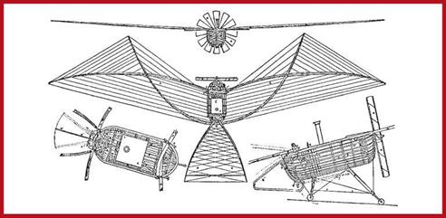
I Patent drawings of Felix de Temple de la Croix’s aeroplane as envisaged in 1874
|
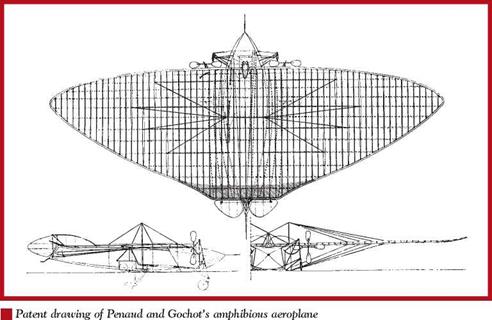
 Meanwhile, after building an ornithopter model with P. Go – chault, in 1876 Alphonse Pennault designed and patented a large two seat flying wing monoplane. This was amphibious, intended to depart and alight equally well on water, or on land. Pitch stability was achieved by locating the centre of gravity forward of the wing’s centre of lift. Roll stability was attained by wing dihedral, and longitudinal stability was bestowed by a fin. Controls included an elevator and drag rudders at the wingtips.
The design had many advanced features. The multi-spar wing was to be metal covered, and the cockpit was to be glazed and fitted with a single control stick actuating both elevator and drag rudders. A neat instrument binnacle, whose likes were to remain in the realm of wishes as late as the First World War, was designed. It included a compass, a barometric altimeter, a speedometer and an incidence indicator. An automatic pilot was also foreseen, comprising a sensor (suspended below the fuselage to warn of ground proximity), and an electrical mechanism controlling elevator and drag rudders. The four-wheeled undercarriage had rubber and pneumatic damping. The propeller blades featured variable pitch, intended to make better use of the 30hp engine on take-
|

| Approximate model of de la Croix’s aeroplane displayed at the Musee de l’Aviation in Paris
|
|
|

Teleshov’s 1867 delta-winged aeroplane was among the more visionary designs of its time
|
|
off: early in the run, the pilot was to keep pitch coarse, allowing engine revolutions and momentum to build up. Prior to unstick, he would suddenly set very fine pitch, transferring power to the propeller. The latter was to be made of metal for greater stiffness.
When taking off and landing on water, the aeroplane was to float on its belly or on ski-like surfaces. Additional floats were to be fitted to the wing for longer stays on water. Calculated gross weight with a two-man crew was up to 1200kg, and speed was up to 90km/h. Embodying some very forward thinking, Pennault and Gochot’s aeroplane was many decades ahead of its time.
Progress in designing heavier-than-air flying machines was also hampered by the lack of scientific understanding of aerodynamics. Important contributions to fixed wing heav – ier-than-air flight were made by the Comte Ferdinand d’Estergnaut, L. P Molliard, and Otto Lilienthal. The latter carefully researched bird flight and described how birds glide and maintain height. In 1863 photographer Felix Tournachon, better known as ‘Nadar,’ established a Society for the Encouragement of Flight With Machines Heavier than Air in Paris. At the first meeting of the United Kingdom Aeronautical Union on 27 June 1866, Naval Engineer Francis Herbert Venham proposed a scientific study of wing shape and profile. His major source had been the observation of nature. Noting that birds’ wings were thicker at the front and the root, and tapered towards the rear and away from the root, he concluded that long, narrow wings (with greater aspect ratio) would give more lift. Another aerodynamics pioneer, H. F. Phillips, used the wind tunnel he had invented for a series of experiments with convex wings of various thickness and degrees of convexity.
|
|
Completing his work in 1884, he proved that lift derives from the difference in air pressure above and below the wing, and patented a number of wing profiles.
By the early 1880s, differently powered aeroplane designs had been produced by, inter alia, Mouillard (France, 1876), Mikulin (Russia, 1877), Taitin (France, 1879), Kerhoven and Speers (Britain, 1881), Shishkov (Russia, 1882). But most remarkable for its time was the design by Aleksandr Fyodorovich Mozhayskiy. He had experimented with flying models until early 1877, achieving a measure of success. He then sent the War Ministry a project for a full scale aeroplane, and set about drawing it without awaiting the reply. The drawings showed a monoplane with a single puller and two pusher propellers. Mozhayskiy proposed a flat wing of modest aspect ratio, set at an incidence to create lift like a kite. Total cost was estimated at 19,000 roubles. The War Ministry failed to appreciate the project’s potential and made available a small sum, spent before the aeroplane’s model was built. Nevertheless, Mozhayskiy went on pursuing his goal. In 1881 he received Russia’s first patent for a flying machine. Construction of the aeroplane began the same year. Two steam engines built to Mozhayskiy’s specifications arrived from Britain. The following year, part of a military estate near Sankt Peterburg was allocated for the project’s needs. Work was completed by mid 1883, and on 7 June an Application for the Performance of Flights with Airborne Apparatus was sent to the Sankt Peterburg Military Region Guards Staff.
Records depict Mozhayskiy’s aeroplane as a twin engined monoplane with a boatshaped fuselage and cloth-covered timber structural elements. The fuselage also housed fuel and the pilots. The wing was fixed to the fuselage’s upper edge. It spanned 23m, and had an area of 330sq m. The empennage was fixed to the aft fuselage and comprised an elevator and rudder for directional and pitch control.
|
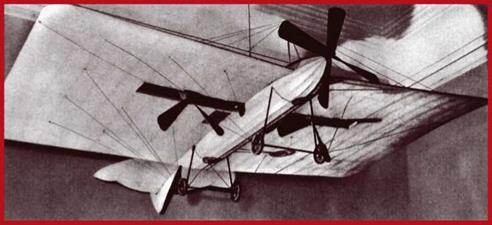
Model of Mozhayskiy’s aeroplane at the Monino Museum of Aviation and the Air Forces
|
|
THE MOZHAYSKIY’S AEROPLANE, 1881
|
|
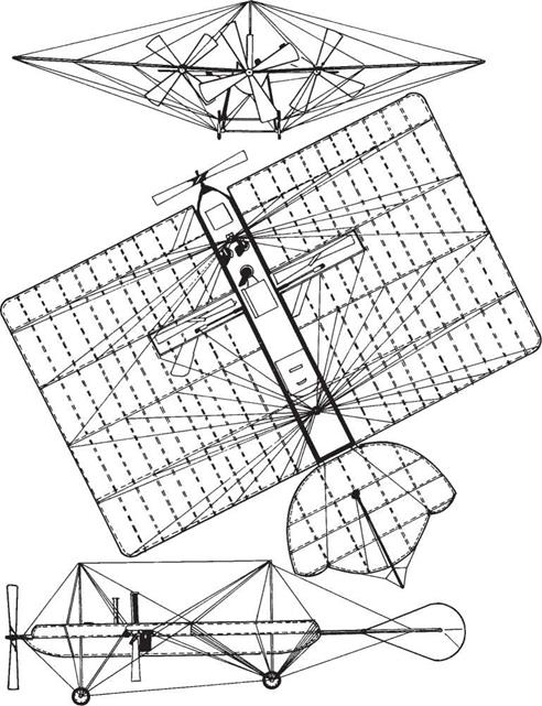
Powerplant comprised the aforementioned two steam engines which shared a naptha-heated boiler. Their respective outputs were 10 and 20hp. For maximum weight reduction, many parts were hollow. This, and other design features resulted in a power to weight ratio of 5.5hp/kg (engine weight plus boiler, condenser and separator): a figure without equal at the time. The smaller engine was located forward and drove a puller propeller with four blades. The bigger engine sat in the mid-fuselage, at one third of wing chord. It drove two pusher propellers located within the wing. All propellers were wooden and had a 4m diameter.
The aeroplane was to depart from a timber ramp (which could be set a different slope angles to assist acceleration) on a four-wheeled undercarriage. Three roll indicators, a compass, and a barometer were to be fitted.
Mozhayskiy tested his aeroplane in 1884 and 1885. Trials included engine starts, taxiing and an attempted take-off. Even though the machine failed to become airborne, it provided valuable data for later use. The poor aerodynamics of low aspect ratio wings became apparent, as did the issue of lateral stability, and the need for completely different engines with reasonable power and relatively low weight and size. Despite Mozhayskiy’s attempts to improve engine output at the Obukhov Works, the futility of such an exercise became apparent, and work ended.
The efforts of numerous scientists, engineers, inventors and enthusiasts to solve the engine problem began bearing fruit. Following in the footsteps of compatriot N. A. Otto, German Gottlieb Daimler developed a new type of gas engine fuelled by a volatile liquid known as gasoline. Fitting such an engine to a flying machine was a safety challenge. This applied especially to lighter-than-air machines where gasoline would coexist with an enormous quantity of hydrogen. Nevertheless, the new engine’s great power to weight ratio, and the lack of heavy subsidiary devices such as steam tanks, accumulators and condensers, made it very tempting.
Having read of Carl Wolfert’s work on small man-powered aerial vessels, Daimler approached him with a proposal to pool their work. Trials of a single seater gas balloon fitted with a single cylinder Daimler engine started in 1888. At a power rating of 2hp, the flying machine showed reasonable results. Since the engine was rather close to the balloon envelope, exhaust gases were ducted away along a special pipe. However, even this was far from safe, but Wolfert felt he was on the right track and started planning a larger vessel.
While the engine breakthrough had arrived, the new engines’ power to weight ratios were still too low for the needs of powered heavier-than-air flight. This is why aeroplane designers in the last decade of the 19 th Century continued looking to steam. In 1890 French engineer Clement Ader completed a rather strange looking aeroplane. Design and construction had taken a long time, having started in 1882. The gifted engineer had chosen the bat as prototype. All work proceeded under a cloak of secrecy, using Ader’s adequate private funds.
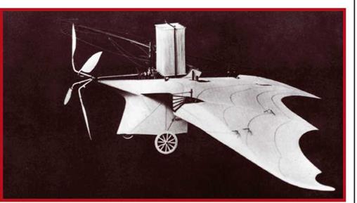
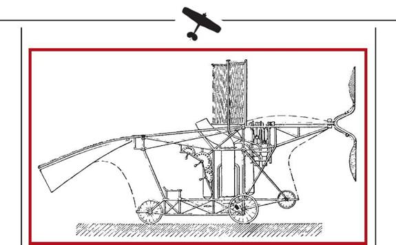
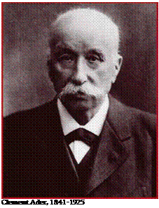 True to intention, the Aeole did indeed look like a bat. This flying wing monoplane with a wing area of almost 28sq m, and 14m span, was made of cloth-covered bamboo.
The enclosed fuselage housed a steam engine, controls, and the pilot. There was no fin. A four bladed propeller of 2m diameter pulled the craft. Movement along the ground was on a tricycle undercarriage with a guard wheel forward. Thanks to its lightweight structure, empty equipped weight was just 175kg, with a gross weight of 296kg.
A most intriguing Aeole component was the 20hp steam engine. Thanks to Ad – er’s refinements, its power to weight ratio was some 3hp per kilo: the Aeole’s had five times more overall power per unit of weight than Mozhayskiy’s aeroplane! Another novelty concerned control. Copying the movements of bats’ wings, Ader articulated the Aeole’s wing to allow changes in sweep, span, camber, and tip deflection. Though these could be made individually or simultaneously, no explanation underpinned the sense behind any of them. Overall, the controls were exceptionally complex and hard to manage.
|
I Model of the Aeole
|
|
|
I Working drawing of the Aeole
|
Trials began on 9 October 1890 in secrecy. This explains why data reaching us today is so scant. In an unfinished report, one of Ader’s assistants describes the Aeole, controlled by the designer, lifting a few centimetres off the ground, staying airborne for five seconds, and covering some 50m. This result could hardly be called a flight, and in any case the craft’s instability and uncontrollability would have rendered longer hops impossible. Nevertheless, the event was significant in the aviation, being the first recorded instance of an aeroplane taking off from a flat surface under its own power. The Aeole showed that aeroplane makers were about to overcome the power barrier.
Although sufficient effort was expended to keep these events from becoming public knowledge, they did not remain unknown to the French military. The latter saw in them prospects for the future, and a superior alternative to the unstable and uncontrollable tethered balloons they were using for observation and reconnaissance. Hoping that Ader would be able to build an improved model to supplant balloons and deliver air strikes, they subsidised him with 650,000 francs. Work was to continue in deep secrecy.
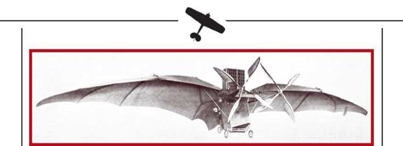
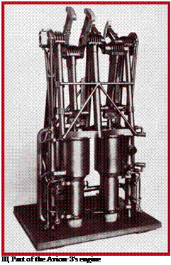
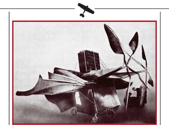
This financial injection allowed Ader to recruit more assistants. Design, production and assembly continued from 1882 to 1887. The Avion-3 resembled the Aeole: a batlike flying wing monoplane. Main difference was the addition of a second engine. The twin 20hp steam units shared a boiler and spun two 3m diameter propellers. Mounted on the leading edge, the propellers turned in opposing directions to cancel out torque. Less articulated than that of the Aeole, the wing had a span of 16m and an area of 56sq m. Only sweep remained adjustable, being changed simultaneously for both wing halves.
|
I The Avion-3 ready to attempt to fly
|
|
A fin gave lateral stability, and there was a steerable tailwheel beneath. Turns were to be accomplished by varying propeller speeds. The pilot sat in an open cockpit behind the engine which resulted in poor forward visibility and problems in steering straight while taxiing and ground running. Gross weight reached 400kg.
First trials took place on 12 October 1897. Plans included accelerating along a specially constructed runway. This was circular, with a 1500m perimeter and a width of 40m. Weather after passage of a rain front was perfect, and the ground was dry. During acceleration, Avion-3 reached 24km/h, Ader using a small portion of engine output. Ground tracks after passing 18km/h were practically unnoticeable, which made
 those present consider the chances of successful flight very good.
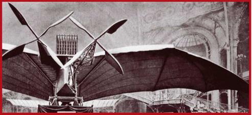
The flight attempt came on 14 October, Ader considering himself sufficiently ready. Unfortunately, a gusting wind appeared. During the takeoff run a powerful gust from the side deflected the lightweight machine from the runway, pointing it at a fence. The pilot remained calm, managing to brake and emerge unharmed. However, the machine’s wing, landing gear and propellers were seriously damaged. This put an end to the talented engineer’s aviation efforts. Testing halted. The military lost interest in the project and stopped funding. Though Avion-3 was restored, its future career was as a display item in the Paris Musee des Arts. In aviation history, this bat-like device remains the first heavier-than-air flying machine to have overcome the power bar-
|
The Avion-3 with wings folded for transporting
|
|
Щ The Avion-3 as displayed at the Palais des Arts ae des [crafts] in Paris
|
rier (and that with a steam engine). Some specialists claim that Ader’s failure was due to slavish copying of bats. This certainly resulted in both imperfections and overcomplexity. Nevertheless, man’s effort to conquer the air — or to complete air power’s first component, to put it another way — continued.
In 1890, the Russian War Ministry accepted a proposal by Vladimir Konstantinovich German for a human – powered or petrol engined monoplane. This was Russia’s first attempt to put an internal combustion engine (rated at 0.5hp) into an aeroplane. In other ways, the design was rather unsophisticated, and funding was declined.
The same year, Frenchman Graffi- ni proposed a kite – like flying machine powered by an engine using compressed carbon oxide gas. It was estimated to fly at 36km/h and have several hours’ endurance. In case of engine failure, the wing was to act like a parachute, permitting a safe landing.
The lack of suitable engines at the end of the 19th Century was one of the reasons why gifted designers directed efforts at unpowered flight. A leading figure here was Otto Lilienthal, a German engineer from Pomerania.[2] His first 1889 glider was a primitive contraption of cloth-covered timber.[3] It insufficient strength and the lack of stabilisers spelt its demise. In 1890 Lilienthal built two more gliders, the second of which had a fin. This was the first device to accomplish a successful glide. However, its performance was poor due to excessive wing curvature. This was corrected in the next design which also featured a tailplane. The benefits were apparent, especially in stronger winds. In 1892, the designer attained an eight to one glide ratio.
A year later, Lilienthal built the glider that would serve as prototype for his subsequent monoplanes. A novelty alongside the strengthened wing, was the movable tail – plane. Counteracting a spring, aerodynamic loads could deflect it upwards, this flaring the wing for softer landings. Lilienthal performed a number of successful flights with this device. Distances covered reached 250m, with flight times of up to half a minute. The glider’s properties encouraged construction of two improved versions. One was an 8m span monoplane fitted with a 2hp single cylinder engine. This was to be used as a subsidiary aid while gliding between thermal currents. Moving the wing, and specifically its feather-like tips, created propellant thrust. Powerplant weight was 20kg and the design-
|
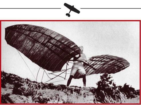
I Otto Lilienthal accelerating with his Glider No3 in 1891
|
|
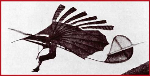
Щ Lilienthal’s motorised glider
|
er had envisaged that the engine would work for not more than half an hour. In any case, engine problems meant that the device was tested only as a pure glider.
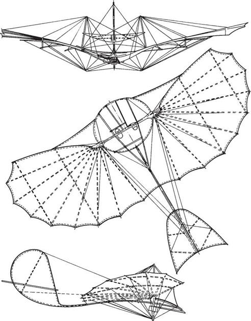
Engine problems made Lilienthal return to unpowered gliders, and in 1894 he built his smallestone, spanning just six metres. A similar model can be seen at the Vienna Technische Museum to this day. The same year also saw Lilienthal’s ‘standard’ glider, whose wings could fold for transport and storage. The tailplane was moved a
|
THE OTTO LILIENTHAL’S ‘STANDARD’ GLIDER
|
|
|
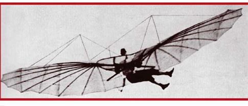
Щ Lilienthal’s ‘standard’ glider which found a fair following among late 19th Century birdmen
|
|
metre further aft to improve stability. Nine such gliders were made, making the device the first heavier-than-air craft to be produced in numbers.
Despite his growing fame, Lilienthal realised that his gliders were rather unsafe for widespread use by untrained people. He therefore built a special experimental glider with automatic leading edge droop to prevent sudden dives. Another novelty was the ability to cut speed using the movable tail, and the dihedral control mechanism. The pilot hung vertically, changing flight direction by swinging his legs and lower body, the additional features working automatically to assist his intentions.
After several flights without much success, Lilienthal abandoned such designs and went on to build biplanes. The first of these saw light of day in 1895. The idea was to allow flight in crosswinds of up to 5-6m/s. The glider demonstrated perfect stability, rewarding its designer by overcoming sidewinds of up to 10m/s.
Lilienthal had not given up the idea of powered gliders with moving motive surfaces. As distinct from the 1893 model, the new design featured a two-cylinder engine. Only the airframe was completed in 1896. This monoplane spanning 8m, and with an area of 17sq m, was never tested due to Lilienthal’s untimely demise
|
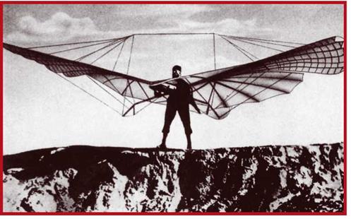
I One of the last photographs of Lilienthal, this time with his No17 ornithopter/glider
|
while gliding. The famous German had flown over 2000 times and left many trained disciples.
Unaware of Ader’s work, prominent British inventor Hiram Maxim[4] set off to build a steam powered aeroplane in 1890. He studied the propulsive efficiency of different propeller shapes in a wind tunnel of his own design, using custom instrumentation. Upon gathering some empirical data, he determined optimum blade and wing shapes and over the following three years built, at a cost of some 20,000 pounds Sterling, an aeroplane which differed from all previous designs in size and propulsion system. Span came to 32m, and wing area to 370sq m. Twin elevators were located fore and aft of the wing, but there was no fin or rudder. Gross weight reached 3.5 tons.
Powerplant consisted of two compound steam engines manufactured of high grade steel. Carried on a steel tube cradle beneath the upper wing, they turned two 5.4m diameter propellers. System power to weight ratio was 1.2kg per horsepower. Fuel was naphtha. The crew sat behind the boiler and condenser. Overall cradle and engine weight was almost a ton.
Maxim underestimated the importance of balance and controllability. Control was limited to the twin elevators. Maxim was convinced that dihedral by itself bestowed sufficient lateral stability. A 600m long rail track with buffers at the distant end was built for the trials. Maxim also provided a height governor which limited
|
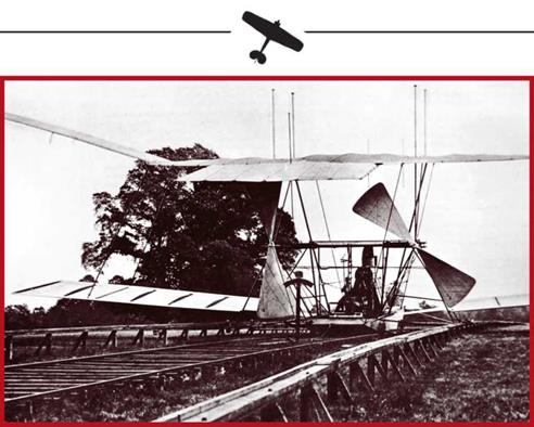
I Hiram Maxim’s aeroplane on its acceleration rail
|
excursions to 0.6m off the ground. This was to be used initially as a precaution against mishap. Famous sportsman and mechanic De Lambert, experienced aeronaut and speed boat tester, was invited to pilot the craft. After several test runs, a date was set for the flight attempt on which the engines would work at full steam.
On 31 July 1894 De Lambert waited for steam to build up and released the enormous craft’s brakes. Acceleration was rapid, the two front wheels lifting clear of the rail. Since the entire weight was now over the rear wheels, they bent the rails, but the latter coped. Maxim claims that 300m after the start of the run the aircraft lifted off the rails, banked slightly and fell to earth, the wheels sinking into soft ground. According to Maxim’s calculations, lift had reached some five tons in the closing stages of the run: half as much again as the gross weight; this was sufficient not just for horisontal flight, but also for climbing and certain manoeuvres. As with Ader’s experiments, the power barrier had been breached, stability and controllability coming to the fore. Maxim undertook no further trials, but showed his machine to friends for a further year, turning it into something of a local attraction.
Otto Lilienthal’s former students and assistants made a great contribution to aviation development. At the time, their newspaper photographs had travelled the world giving them universal fame. One of them was Scottish naval engineer Percy Sinclair Pilcher. After working with Maxim for some time, he went to Lilienthal in Germany and learned to glide. In 1896, Pilcher patented a monoplane distinguished by large
wing area. Its trials confirmed Lilienthal’s belief that a small aircraft could be controlled adequately by body balancing. However, the Gull crashed twice in high winds, and Pilcher stopped using it. The same year he completed his Hawk, very similar to his mentor’s ‘standard’ glider. The pilot occupied a cutout in the centre wing, and the moving tail gave good controllability, especially at high angles of attack. The fourwheeled sprung undercarriage was a novelty helping ground acceleration and softening landings.
Initially, Pilcher attained distances of up to 90m in the Hawk, this being bettered to over 200m the following year. Thanks to its adequate stability and modest size and weight, the glider had good controllability for its time. Pilcher was able to make turns and control landing speeds.
Right from the start, Pilcher intended to fit engines to some of his designs. The Hawk being most suitable, he decided to fit it with an internal combustion engine driving a pusher propeller. The craft would be launched as a glider, its pilot running downhill. Once airborne, the 2-4hp class engine would be started to help maintain a 30km/h speed. Control would be by balancing, the pilot switching positions or swinging his legs and pelvis. Sadly, a suitable engine was found only in late 1899, and this was never tried, Pilcher finding his demise in a gliding crash. British aviation hopes were severely dashed with the loss of this man who combined the requisite technical background and flying experience.
Otto Lilienthal’s work had attracted the notice of one Octave Chanute: French Baron by origin, US citizen by choice, and Chicago structural engineer. Aware of Cayley, Hanson, Stringfellow and other aviation pioneers’ work, in 1894 he published The Progress of Flying Machines. Lilienthal’s example made him think of trying his
|

I Pilcher’s Hawk glider
|
luck at designing his own flying machine. In 1896, aged 64, Chanute built two gliders. Advancing age meant he had to ask young engineer Augustus Herring to fly them. The first glider failed to live up to expectations due to poor finish and low controllability. But the second one, a simple, lightweight and tough device, turned out to be the best balanced glider of its time. Assessed by specialists as setting new aviation design standards, it was used by the Wright brothers in their work some time later.
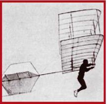
The glider’s most notable feature was its wing. A biplane, it had a structure of timber spars, ribs and stays: bridge design knowledge applied to aeroplanes. The ruddered fin allowed the glider to counter crosswinds of up to 14m/s. To ease control, the pilot sat suspended in a sling. Spanning some 4.9m, the glider weighed just 10.5kg. In 1896, the biplane was tested at the sand dunes on Lake Michigan’s shore, flying some 1000 times. The greatest distance covered was 100m, in 14 seconds.
Later Herring was to build his own large triplane glider which would cover 280m. (Explaining this achievement, he stressed not the glider’s superiority, but the growth of his own piloting ability.)
Herring learned to make smooth turns and flew around hills in search of thermal currents.
Encouraged by success, the engineer decided to go for the next step: powered flight. Initially he intended using two lightweight petrol engines of some 2hp each. Sadly, this class of щ Octave Chanute’s biplane glider which engine was rather heavy at the time, so Her – flew successfully between 1896 and 1904
ring opted for a compressed air powerplant. The twin cylinder engine weighed six kilos and developed 3 to 5hp for some 30 seconds.
Completed in summer 1898, the monoplane was tested at the Michigan lakeshore between 10 and 22 October, with decidedly mediocre results. The longest hop achieved was just 22m in a little under ten seconds. This convinced the designer that he had to have a more powerful engine which would work longer. However, by weighing down the craft, this clashed with its very concept. Circumstances dictated a different acceleration method and precluded control by balancing. Herring failed to find the right solution and gave up.
Meanwhile, Wolfert and Daimler’s joint efforts continued. The result was a large airship fitted with a 6hp two cylinder internal combustion engine with exhaust pipes. (From now on, the exhaust would feature in all of Daimler’s engines.) The machine was demonstrated at the 1896 Berlin Exhibition. Kaiser Wilhelm II showed interest in it but declined to ride it. A major disadvantage was the engine’s proximity to the balloon envelope. Critics noted that rapid gas discharges for emergency landings could lead to dire consequences. Wolfert did not view this as good reason to introduce design changes, his only response being to limit flight altitude.
The Kaiser’s attention occasioned great interest in the craft at the Tempelhof aeronautic exhibition which opened on 12 June 1897. A demonstration flight was
|
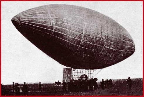
I Wolfert’s dirigible at Tempelhof on 14 June 1896
|
planned to demonstrate the airship to German officers and the Diplomatic Corps. A Prussian Balloon Corps officer was invited to ride with Wolfert and his mechanic. Last-minute inspections revealed skin damage where guyropes had scuffed the envelope. However, the hydrogen leakage was not considered really hazardous or prejudicial to performance. Wolfert did however decided to reduce the load so as to impress the military assessment committee with good climb rates despite the damage. Thus the Prussian officer stayed on the ground, while the airship rapidly climbed to 1000m. At that altitude, Wolfert ordered the engine to be started, and the craft turned into a falling ball of flame. Both aeronauts perished.
Five months later, Tempelhof was to witness a dirigible of completely different design, built by Austrian engineer David Schwartz. In 1896, Frenchman Herault and American Hall invented electrolysis independently of each other. The process was suited to industrial production of aluminium. Schwarz’s dirigible had an envelope and gondola of aluminium sheet over a skeleton of alluminium tubing. The 52m long, shiny, artillery shell-like object was the first rigid airship. Regrettably Schwarz fell gravely ill and died on 11 January 1897. The honour of testing his dirigible in flight fell to Jagel, his capable mechanic, who had no experience as an aeronaut. To add to his troubles, a stiff wind blew up on the day set aside for the first ascent. Alone in the gondola at a height of 300m, the rookie aeronaut tried keeping steering straight but
|
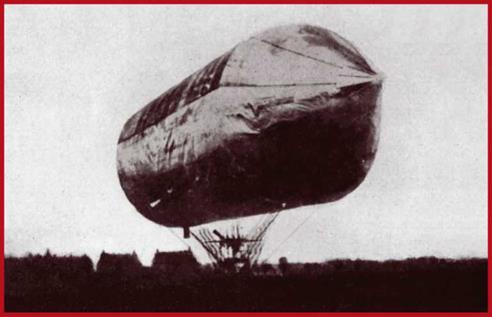
I David Schwartz’s airship was the first of the all-metal rigid type; it is seen here exhibited at Tempelhof on 3 November 1896
|
panicked and broke a control cable. The emergency descent which followed was complicated by unnecessarily rapid gas discharge, causing the craft to strike the ground hard. Jagel managed to jump clear, but the machine was in pieces.
The tragedy did not stop count Ferdinand von Zeppelin from completing an enormous rigid dirigible. The reserve cavalry General had observed the American Civil War between 1864 and 1865 and seen active service in the Franco-Prussian War. He was convinced that even imperfect tethered balloons could influence the outcome of battle. On leaving the army, he began developing a lighter-than-air craft with much broader combat competence. His new weapon was intended to transform the power of Germany’s rearming army. Design was completed in 1895 and the nobleman was awarded a patent. He set up the Society for the Advancement of Aeronautics, a limited company with an equity of a million marks, half of it invested by himself. Workshops and an airship hangar were built on von Zeppelin’s Bodensee estate. Work began in spring 1899, and a year later the finished article was ready for testing.
The 140m long dirigible had two Daimler marine engines, each rated at 16hp. However, not more than 24hp was actually produced from both engines in ground tests. As distinct from Schwartz, von Zeppelin used not aluminium but cloth to cover the tube structure. The interior was divided into 17 compartments. With two
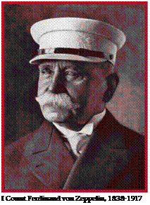 exceptions, they contained gas bags (ballon – ets) with a combined volume of 11,000cu m. The airship was designed to lift a five-man
|
I The LZ-1 before completion
|
crew and enough fuel for a ten hour flight. Designated the LZ, it made an 18 minute maiden sailing from the Lake Konstanz naval hangar on 2 July. An 80 minute sailing was recorded on 17 October. Testing showed up insufficient stiffness and poor load trim, resulting in control difficulties. The engines were also insufficiently powerful. Despite this, another sailing was made on 24 October before the designer decided to halt further tests. Forced to repay creditors, von Zeppelin had to sell his airship hangar, dismiss workers and cut the airship for scrap.
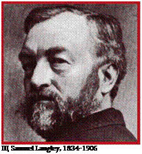
Samuel Langley’s steam powered model aeroplane was the 19th Century’s most advanced aeroplane. During its 1896 tests, it covered over a kilometre. Some years were to pass for this exceptional record to be bettered. These tests also marked the end of the model aeroplane era in aviation development. The possibility of making a powered heav-
ier-than-air flying machine was now proven. The US government showed an interest in Langley’s work. The 1898 Spanish-American War spurred American ambitions to possess an all-new weapon which could grant the US regional and world supremacy. The significant sum of 50,000 dollars was set aside to subsidise developments.
The airframe of Langley’s aeroplane was ready by late 1900. What distinguished it was its tandem wing layout and cruciform tail. Overall wing area was 95sq m. The body was a flat frame supporting an open cockpit. Body length was 14.5m. The earlier models’ superb stability recommended the replication of their control surfaces in full scale form. The aeroplane had a 50hp water-cooled steam engine weighing 94kg: the lightest aero engine of its period.
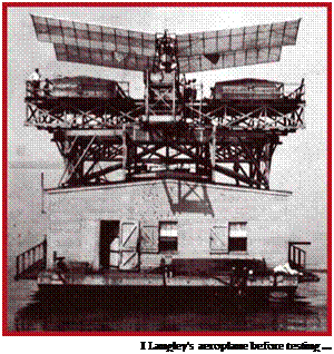 The scale model flights and the availability of a powerful and light engine raised hopes of success. Regrettably, both flight attempts failed. Pilot Manley got into trouble from which only quick thinking and reflex saved him.
Failure turned the press against Langley and project funding halted, forcing him to stop further work.
Not surprisingly, Wolfert’s tragic fate turned official circles against non-rigid balloons fitted with internal combustion engines. However, balloonists continued flying such rigs. Formed in Paris in 1898, France’s first Aero Club could use the Saint Cloud airfield. One of its most enthusiastic members was Brazilian Alberto Santos-Dumont.
|
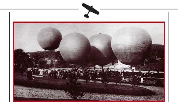
Opening of the French Aero Club, Saint Cloud, 1898
|
|
After a false start on 28 September 1898, two days later he performed the first in a series of successful ascents with a de Dion petrol-engined non-rigid airship. In 1901 Santos-Dumont won a large cash prize for flying from Saint Cloud to the Eiffel Tower and back: a distance of some 24km covered in an hour and a half.
While not a major designer, Santos- Dumont was a superb pilot and had the great advantage of sufficient money to carry on improving. He was a ‘born aeronaut,’ and if Meunier, Gifard and Renard showed the world how to build non-rigid airships, Santos-Dumont showed it how they ought to be flown.
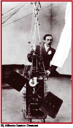 Despite its inherent conservatism, Britain did not lag behind in the rapid de – velopment of aeronautics at the turn of the Century. Animated discussions were held about the relative merits of lighter versus heavier-than-air craft. Established in 1866, the Aeronautical Society grew
|
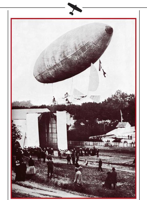
I Santos-Dumont’s historic flight
|
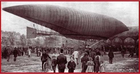
rapidly, becoming an Aero Club in 1901 (later The Royal Aero Club). Despite this activity, powered balloon trials were rather fewer than in France. The turning point came with Stanley Spencer’s 1902 flight. His 28.5m long, 6.6m diameter airship had a single seat cabin and a 3.5hp Sims water cooled engine. This ran at 2500rpm: so fast for its time that a reductor was needed. On 22 September 1902 Spencer flew from Crystal Palace in South East London to Inchcoates in Middlesex, covering the 100km distance in 100 minutes. Later the same design made other successful flights. Having acquired serious experience, Spencer built a larger airship which, however, failed to live up to expectations.
The same year French engineer Henri Juliotte completed a semi-rigid airship. It had been commissioned by sugar refinery owners, the brothers Paul and Pierre Lebau – di. The elongated balloon envelope was 62m long. Powerplant was a 40hp Daimler engine. Form early in the winter in 1902 until summer 1903, 30 flights were performed from the Matesse base. Maximum still air speed was 40km/h. One of the flights, in November 1902, was symbolic: from Matesse to the Champs de Mars in Paris, where Professor Charles had flown the first hydrogen balloon in 1783. Mean cruise speed was 35.5km/h.
Despite dirigible successes, the military stayed faithful to non-rigid and semi-rigid tethered balloons: they were battle proven. Armed forces in several countries made efforts to improve such balloons for reconnaissance purposes. Naturally, this was still far from the creation of a component of air power. Until the late 19 th Century, the military had used almost exclusively spherical balloons. Despite being useful in African colonial wars, they also had numerous limitations. For instance, in Southern Af-
I Newspaper drawing of Paul and Pierre Lebaudis’s airship
rica the British Army found that wind speeds of over 35km/h rendered ascents impossible due to drag. The balloons swayed unacceptably even in slight gusts, making the observer unable to use optics. This resulted in altitude restrictions which reduced the area under observation. Clearly, a stable aerial platform was needed.
Encouraged by the War Office, after the Boer Wars some British inventors tested man-lifting kites. Most active was Texan-born Samuel Cody. He built kites similar to those made by Baden-Laulel and used Hargrave’s sling system. Experiments in Britain and Russia confirmed concerns that the kites would be worse than balloons in strong winds. Another direction of work involved attaching kites to balloons to stabilise the latter. Such experiments had a history dating to before 1885, and showed much promise.
The military were hastily seeking new and sufficiently effective reconnaissance platforms. Almost half a century earlier, Klausewitz had stressed information procurement by writing that whichever side knew more about its adversary had the battle half-won. Developments of the new type of balloon proceeded fastest in Germany. There, scientists were working on a new and stable aerial observation and artillery direction platform. As early as 1886, Major August von Parcival and Captain Bartch von Siegsfeldt had patented an unfortunate looking but practical kite balloon. Trials of the new design started in 1893, and the following five years saw variations with volumes of between 600 and 1200cu m tested. They ultimately evolved into ‘sausage’ balloons used on both sides in the Great War, and to guard London, Moscow and other cities from air raids in the Second World War. Main material was rubberised
|
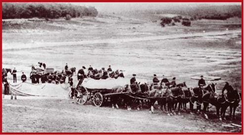
A British balloon unit during the Boer Wars
|
|
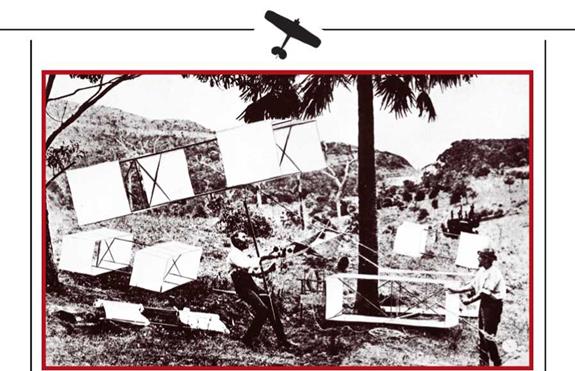
Lawrence Hargrave preparing one of his kites for a flight
|
cotton. Anchored by guy ropes, kite balloons flew into wind at some 30 or 40 degrees of incidence. The airstream created additional lift. For greater stability, the design incorporated a guide sleeve and a guide sail on each side of the main envelope. Observation was from an altitude of 2000m, entirely adequate for normal reconnaissance.
|
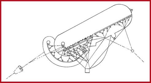
Instructional drawing of a Parcival-Siegsfeld kite balloon
|
Combat proved the benefits of the new balloons. At the onset of the 1904-1905 Russo-Japanese War, the Russian side used indigenous spherical balloons to support its forces and coastal defence in the Port Artur area. The Russian engineering unit officers who operated them soon encountered the customary stability problems. They then tried kites, to no appreciable improvement. Only the introduction of Parcival-Siegsfeldt kite balloons made a difference. Navy needs were served by a specially equipped mother ship which would launch kite balloons. However, due to engine trouble, the cruiser did not see active service. Russian specialists also developed a new, lighter method of charging balloons with hydrogen, allowing them to be replenished closer to their ascent sites. The fact that between 1914 and 1918 the warring sides used no fewer than 5500 kite balloons shows how well the two Germans handled their task.
The emergence of the basic component of air power did not involve only aeronautics and aerostatics. At the turn of the century, two brothers who manufactured bicycles in Dayton, Ohio, began actively researching aviation. Influenced by Otto Lilienthal’s famous successes, in early 1899 Wilbur Wright wrote to the Smithsonian Institution asking for books and papers on heavier-than-air craft, giving Chanute’s monograph as an example.
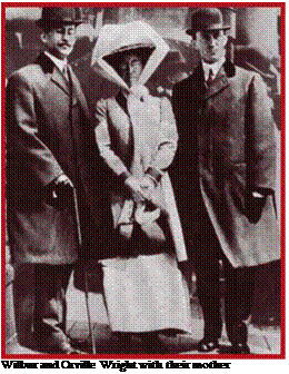 Soon after receiving the requested literature, he and his brother Orville built a biplane kite. The aim of this first experiment was to test Orville’s contention that birds balance and turn by twisting their wings. The kite had a special control cable which changed wing camber as needed to react to wind direction and speed.
This control system was amplified by a canard elevator (one fixed forward of the wing).
The following year Wilbur wrote to Chanute asking for comments and advice on the brothers’ new biplane glider. Spanning 5.5m, this resembled Chanute’s design in its structure, but everything else was the fruit of the Wrights’ own creative thought. They believed that if they coped with controlling the glider, they would succeed in building their own powered aeroplane. The idea was to make an unstable aerial platform whose trim would depend on the pilot’s coordinated movements, much as a bicycle depends on the rider’s balancing
|
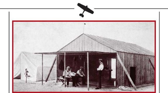
I Octave Chanute visiting the Wrights at Kitty Hawk
|
|
movements. Lilienthal controlled his gliders by swinging his almost vertical body, but the Wrights chose a prone control position from the outset. The pilot was to twist the wings to maintain an optimum glide angle, and use the canard elevator to control sudden downward pitch (such as the one which had killed Lilienthal).
Trials of the glider began in late summer 1900, near the town of Kitty Hawk, North Carolina. The Wrights had chosen the hilly site because of its excellent year – round weather. The proximity of the Atlantic provided a stiff breeze of constant direc
 tion and speed. Most flights were unmanned, the glider flying as a kite. Some tethered flights also took place. Just one piloted glide was flown.
In July and August 1901, the Wrights began trials of a larger glider, spanning 7.3m. Though essentially unchanged, its control system was developed and improved. This time the Wrights went to Kill Devil Hills, four and a half miles south of Kitty Hawk. While one piloted, the other helped by steadying the glider and running alongside until it was airborne. Several exceptionally successful glides were performed, including one of 110m. The designers noted a tendency to sideslip when one wing half was twisted independently of the other.
On returning from this season’s flying, the Wrights reassessed their theory in the light of practical experience. They also carried out a number of tunnel tests using a pedal – driven wind tunnel. By late summer 1902 the brothers built their third biplane glider, with a span of 9.15m. To counter sideslip and ease turns, the tail now featured two extra fins.
In the second half of September, the glider was taken to the Kill Devil Hills sand dunes. During initial flights, wilful or accidntal (caused by the wind) camber changes to one wing half were found to result in yawing and rolling. The problem was solved only when the twin fins were replaced with one and this was made to swivel by being geared to wing camber changes. The modified glider could now turn fairly flatly and was even controllable in Beaufort Force Seven winds. The brothers patented their method of control by jointly twisting the wing and fin, but the patent was to lie fallow until 1906: other flyers were far behind in their endeavours.
|
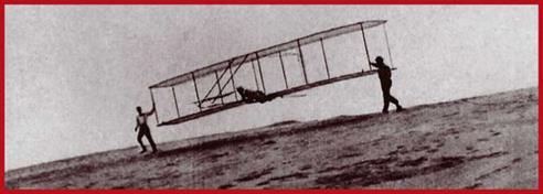
Launching a Wright glider
|
|
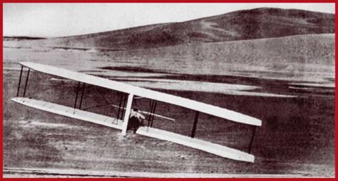
A Wright glider about to land, October 1902
|
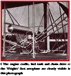 Successful glides of over a minute’s duration firmly prompted the Wrights to make an aeroplane. The engine installation and propeller were built in the winter and spring of 1902 and 1903. Progress was easy because, as distinct from all their predecessors, the brothers were not aiming at a super light powerplant. All they had to do was adapt a water-cooled four-cylinder petrol engine by stripping away unnecessary road-going complications and weight. It weighted 90kg and developed 12hp: a power to weight ratio of 7.5kg per horsepower, or rather worse than the steam units of the late 19th Century.
Still, good aerodynamics meant that the engine was perfectly capable of hauling the flying machine into the air.
The propeller resulted from exhaustive wind tunnel testing in 1902 and 1903. The Wrights viewed it as a spinning wing and tried to find the best profile for each spanwise propeller section. The result was a new record in propeller efficiency: 66 per cent. Transmission was by bicycle chains which also acted as reductors. Overall transmission and propeller weight was 41kg.
In other respects, the aeroplane was similar to the 1902 glider. The higher weight called for a span increase to 12.2m and for increased control surface area, the latter achieved simply by installing a second elevator and rudder. Skids were mounted under the wing to soften landings: wheels would be of little use on the sands of the North Carolina coast.
The craft was taken to the test site where it was assembled by November 1903. It was a canard biplane with twin 2.6m diameter pusher propellers turning in opposing directions to cancel out torque. The engine was on the lower wing, alongside the prone pilot. The latter controlled wing camber by thigh movements. Two other levers were mounted in front of him: one for controlling the elevator, and the other for starting the engine. Gross weight was 340kg, length: 6.4m, wing area: 42sq m, and span: 12.3m.
Takeoffs were performed using an 18m long steel-plated wooden rail which could be turned to face directly into wind. On departure, the craft travelled on a small wheeled dolly which remained on the ground.
Initial tests involved running the engine on the ground. These showed up weakness in the hollow propeller shafts which had to be replaced with solid units, raising structure weight. On 12 December, the Wrights decided they were ready to fly. They waited for good weather and made their first attempt on 14 December. After a 16m
ground run the aeroplane lifted, pitching up sharply and falling to the ground from a height of 5m. The 32m hop had taken 3.5 seconds. Pilot Wilbur Wright was unhurt and damage was insignificant. The designers realised that the mishap had resulted from incautious handling of the elevator.
The second flight was on 17 December. The wind was stronger on that day, and the guide rail was set almost flat. The flight was successful, lasting 12s. Three further attempts were made, each improving on the duration of the first one. Overall airborne time was almost two minutes, with the final flight lasing 59 seconds and covering 280m.
|
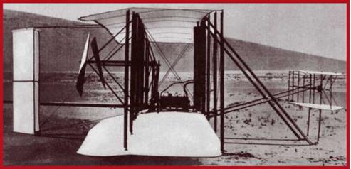
The Flyer, first successful aeroplane in history, before being put on its starting rail
|
|
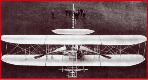
Щ The Flyer on its starting rail
|
|

17 December 1903: the second of the day’s flights
|
Naturally, these were not flights in the proper sense of the word, since Wilbur Wright made no attempt to vary the Flyer’s speed or direction. Nevertheless, that day saw the first recorded aeroplane flight with proper control over speed and height.
Using their predecessors’ experience, the Wrights made a craft which not only possessed the necessary power, but also effective pitch and roll control. Due to its static instability, the Flyer called for fine piloting skills: something the Wrights had only begun building up in late 1903. The tests were the first successful flight of a heavier-than-air machine: powered take off, level flight, and landing with a man on board.
There now followed a reassessment of the Flyer leading to its improvement. Flyer 2 was completed in May 1904. It differed mainly in having a 16hp engine, but power to weight ratio remained low due to higher all-up weight. Elevator shape was changed and wing profile flattened. The airframe had to be strengthened, increasing empty weight to 320kg. Since tests were to be on flat pastureland near Dayton, Ohio, the craft was reliant on strong headwinds. This limited flying opportunities and made the Wrights dependent on weather. Their answer was an improvised catapult: they built a tower from which a half ton weight attached to the aeroplane would be dropped, launching it along its rail.
The first catapult take off was on 7 September 1904. The flight went well, confirming that tests would be possible without relying on the wind. Flights were becoming routine, and the Wrights’ piloting skills grew. Still, flying was still along straight lines, and still over in mere seconds. The meadow’s size limited flight distances of necessity, and each hop ended with the tedious task of hauling the machine back to the rail. Eventually, the idea of circling flights commended itself.
The first departure with the intention of flying a closed circuit was on 15 September. However, due to the great radius of the turn, Flyer II flew too close to a fence and
|
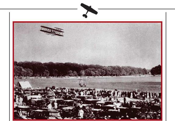
I One of the Wrights’ early demonstration flights at Fort Myer. The pyramid-shaped toner which assisted takeffs is clearly visible
|
had to be landed prematurely. The first successful circling flight was on 20 September. Wilbur Wright completed a 360 degree turn, staying aloft for two and a quarter minutes. It was clear that this method of flying made possible significant endurance without straying off the safety of the ‘airfield.’ Another achievement was marked on 9 November, when 4.8km were flown in 5m 4s. Flyer II was used until 1910, making over 80 successful flights. Nevertheless, the Wrights were dissatisfied with its controllability. Hazardous situations caused by Flyer Il’s unwillingness to comply were commonplace in 1904. Further work was needed.
Flyer 3 was finished in June 1905. The engine was unchanged, but judicious tuning had increased power to 21hp. The airframe was additionally strengthened. The elevators and fins were moved further away from the centre of gravity (which coincided almost entirely with the centre of lift). To reduce sideslip in turns and rolls, two vertical plates were fitted between the twin elevators. Despite these improvements, initial flights suffered from temporary loss of control. By late September, the designers realised their control problem was due to stalling of the control surfaces when reducing speed. Future flights, flown at flatter angles of attack, confirmed this. The control issue was solved!
To ease piloting, controls for wing and rudder twisting were separated. Coordinated rolling turns without sideslip were now possible, reducing the demand on engine
power when turning, rolling and flying figures-of-eight. In summer and autumn 1905, Flyer 3 performed some forty flights near Dayton. On 5 October, the craft covered a closed circuit of 39km in 38 minutes and three seconds: an average speed of 60km/h.
The Wright brothers’ flights were almost totally ignored by the press. Newspapermen refused to take the rumours of successful American powered flights seriously. Airships, with their impressive size and considerably better achievements, made a much better story. The few (factually wrong) press reports that did appear were greeted with a large measure of doubt. One of those who did believe them was Lieutenant Colonel Cooper of the Royal Engineers’ School of Aeronautics. In 1904, the War Office sent him to the Saint Louis, Missouri, Technical Exhibition. While there, he got in touch with the Wrights at Dayton. On returning, he wrote a full report regarding the claimed 1903 flights, adding he was convinced of their authenticity.
THE FLYER III, 1905
101
The British visit and the US government’s interest in Langley’s project convinced the Wrights they had a product they could sell for a lot of money. They believed in the future of the aeroplane as a means of international communication and trade, and harbinger of goodwill. They also foresaw for it a future as a means of warfare. This is why in selling their project they first addressed the United States’ Department of Defense, Orville Wright writing these words on 18 January 1905:
“The series of aeronautical experiments upon which we have been committed these last five years ended with the creation of a flying machine capable of practical use… The numerous flights made confirm that flying can be used in a great many ways, one of which is intelligence gathering and the transfer of messages in wartime.”1
In a 9 October 1905 letter addressed to the Secretary of State for Defense, Orville reminds him of the newly created flying machine capable of use for intelligence purposes. However, perhaps for reinsurance after Langley’s failure, the military did not hasten to buy. Their reasons were reasonable enough. The Wrights’ aeroplanes were unsuited to genuine combat: for one thing, the pilot lay prone, fully exposed to ground fire; for another, there was no room for a second crew member who could observe and recconnoiter from the air. And even the most improved Flyer could hardly maintain a set altitude to enable effective use of optical instruments and cameras. Also, the small amount of fuel limited endurance to below any reasonable duration. Taking into account the Wrights’ high asking price, the double refusal of the Department of Defense becomes understandable.
Negotiations with the Admiralty in London and the French government ended the same way. Despite the interest shown in future improved flying machines, the pioneers lost heart. They were wary of displaying their machines in public, lest their technical secrets be stolen by competitors. After the 16 October 1905 flight, their two and a half years of active flying were over. Mothballed, the machines stayed in storage until spring 1908.
After count Zeppelin’s first attempt to build a dirigible with the sort of performance the military sought, the Schute Lanz company also came up with a rigid airship. Main structural material was timber which was rather heavy, affecting performance. Von Zeppelin gradually became undisputed leader in rigid airships. In 1905, he completed his LZ-2. Similar in size to the LZ-1, its powerplant was significantly more powerful. It was this powerplant that failed on the LZ-2’s maiden sailing on 17 January 1906. Rendered unable to cope with bad weather, and hit by a sudden storm, the Count had to land far from his base. Such was the severity of damage that the craft had to be disassembled where it landed.
None of this was reason to despair (and in any case despair was something unknown to the old soldier). The LZ-3 emerged from its hangar soon enough, and in 1906 and
1 Translator’s rendering from the quotation in Bulgarian.
102
|
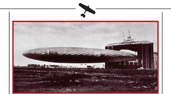
The Schute-Lanz airship being walked from its hangar for tests
|
1907 went on to make a series of successful voyages. It was bought by the Ministry of War who designated it the Z-1. At the same time, von Zeppelin designed the 147m long LZ-4 and offered it to the government. One of the conditions the latter put to him was that it should make an uninterrupted 24-hour voyage. Zeppelin planned to sail from Friedrichshafen to overhead Basle, and along the Rhine to Meinz. In fine summer weather this was easy for the vessel, provided its twin 110hp Daimler-Mercedes engines held out. The LZ-4 lifted off on 4 August 1908 with 12 persons on board (including its designer), The day was warm and conditions looked ideal. Many inhabitants of Basel, Strassbourg,
|
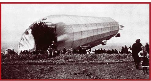
The LZ-2, moments after its accident
|
|
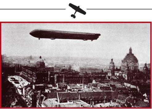
I The LZ-3 over Berlin
|
and Mannheim came out to watch the huge creation of man fly overhead. However, the hot sun overheated the structure and the valves let a great quantity of hydrogen escape from the gas bags. Between Mannheim and Meinz, after more than half the planned voyage was completed, one of the the LZ-1’s engines failed. Count Zeppelin assessed the situation and decided to put down near Oltenheim. Repairs took three and a half hours, and the flight resumed with a reduced load. The next morning, after covering 610km and with just 110km to go, engine trouble again caused an unscheduled landing. The airship touched down gently near the Daimler factory in Stuttgart. Lacking anything better, local volunteers moored it to an undertaker’s coach. A summer storm struck in the afternoon, tearing the airship off its improvised mooring. A fire broke out and the craft was rendered unfit for further use.
The bloodless calamity increased von Zeppelin’s stock. A sympathetic public raised cash to assist his further activities. This made series production of airships and their associated equipment possible. The world press announced the laying down of eight airships and a government prize for the designer. The Count, for whom riches meant little, refused to make non-rigid or semi-rigid airships, however quick the returns. At the time, soft balloons continued to be the only means of aerial observation bought by armies and navies. What really motivated von Zeppelin was to boost German grandeur with an instrument of air power without equal.
At the close of 1909 he assented to the founding of the German Aeronautical Public Equity Company, DELAG. This was to operate seven airships, which in the event made over 16,000 flights carrying over 35,000 passengers before the start of war.
|
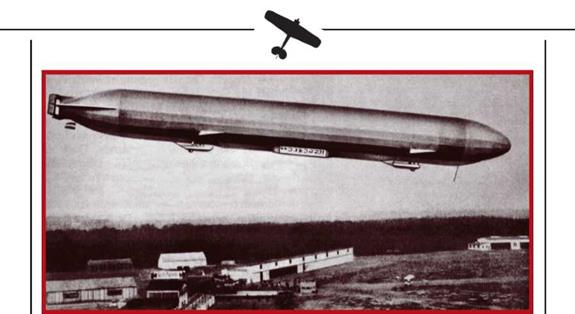
DELAG’s Schwaben airship about to alight
|
The fleet was also used for crew training and moving troops. During the same period the Friedrichshaven airship works manufactured 25 airships. Apart from DELAG’s machines, 12 sold to the Army, three to the Navy, and three remained on the company’s books.
Right since the debut of rigid airships, the German war ministry saw in them a new and powerful strategic weapon. Its great benefit was the great depth of projection, and that in an environment previously untouched by man. Apart from anything else, airship warloads could reach six and a half tonnes. The operational war plan for the Western approaches formulated in 1906 by von Schliffen foresaw German troops entering France and an Army group passing through Belgium. The plan assigned airships to operational and tactical tasks in the service of the Supreme Command and Army Commands. Airships were to bomb strategic targets, perform reconnaissance and strike targets under observation, and perform transportation tasks. The General Staff felt that a lone airship would be able to disperse troops, force the capitulation of fortified garrisons, paralyse communications and supply, cause panic in large cities, and have a psychological effect on troops and civilians. The Germans paid for their overestimation of airships in the initial stages of the Great War: the idea of using them in combat had to be curtailed hastily, and the fascination with them held back German aeroplane making for years.
The initial period of man’s search for reliable methods of conquering the sky ended with the Wright brothers halting flights, Parcival-Ziegsfeld balloons entering production, and the LZ-4 making its first voyage. Three ways to build the first component of national air power. These roads were defined by the nature of flying apparatus, and by the future tasks suitable to each.
The first such road went via non-rigid lighter-than-air vessels: balloons. Going back over a century, their history had led to the tethered kite balloon: an excellent aerial observation platform. Though the nature of their tasks had hardly changed since the French Revolution, they offered much better conditions for the use of sighting and photographic optics. This made them invariable participants in manoeuvres and colonial conflict at the turn of the 20 th Century, and invaluable in reconnaissance gathering and artillery directing. In view of their comparatively long evolution and the considerable accumulated experience in their use, they were both most perfected and most widespread.
The second road led to lighter-than-air vessels of non-rigid, semi-rigid and rigid construction, able to fly freely thanks to being powered. They had evolved from the first balloons which freely followed air currents. The lack of suitable and sufficiently powerful engines was the main hindrance in the way of airships. They failed to find a practical application until the end of the 19th Century. It was only after the appearance of the internal combustion engine that strategists in France and Germany began writing airships into their war plans as strategic intelligence collection and attack platforms. But plans are intentions, not reality: the first airships lacked adequate performance. Army and navy experts were very critical of their slowness, their dependence on medium altitude winds, and their low flight altitude which made them vulnerable even to small-arms fire.
The third and newest road was represented by aeroplanes: heavier-than-air flying machines. Though fragile, the Wrights’ Flyer nevertheless staked a claim for the future with its mobility and compactness. A period of breakneck development over a very short time was about to unfold.
|
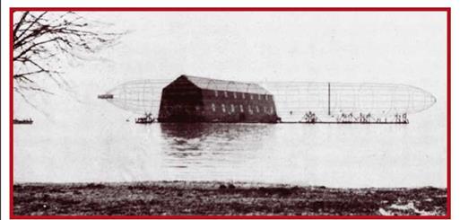
| A Zeppelin airship under construction
|
Regardless of human advance towards the conquest of the air, the components of air power were barely nascent. Most developed was the availability of flying apparatus capable of performing military or civil tasks in a sustained fashion. Yet such apparatus as there was played purely subsidiary roles and lacked any penetration in depth. Such flying schools as were soon to appear trained a very limited contingent of pilots and ground staff. The creation of German airship operator DELAG was a step forward, in that it gave fine training to many flight and ground crews. However, there was still no combat training system in operation. What military theories existed trod well established infantry and naval paths, failing to take into account both the specifics of the new weaponry and that of the environment it was designed for. As to aviation, it was literally still on its starting blocks. One could not speak of the second component: the sufficient availability of skilled pilots and ground crews.
The third component, ground and air equipment, was only developed to any extent in aeronautics. Airborne equipment comprised sighting optics and early aerial cameras. Ground equipment comprised hydrogen production and filling stations. The arrival of airships increased demand for facilities where they could be moored and maintained. This led to the appearance of the first hangars, mooring towers and other station facilities. As aeroplanes developed, so would airfields and eventually airports. Support facilities were limited to a few factories for the manufacture of tethered balloons and workshops catering to the amateur aeronaut trade. Zeppelin’s company, whose core and only activity was aeronautics, was an exception (though it soon became the rule in the industrial nations). It is difficult to discern any command or coordinating structure or system, let alone discuss its powers or effectiveness. Telegraphic transmission tests did take place, but failed to become routine both in the armed forces and in private operators.
The early stage of development determined the limited opportunities of using the air for civil and military ends. The emergence of air potential depended on scaling a number of problems: a challenge calling for both time and money.
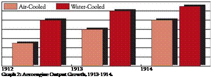
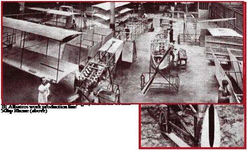
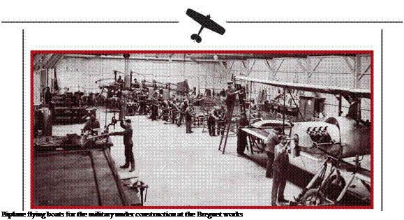
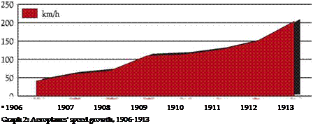
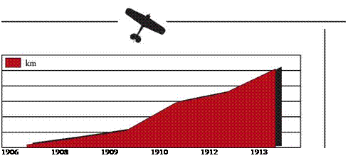
![]()
![]()
![]()
 1000
1000![]()
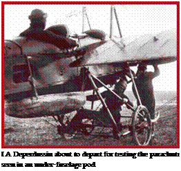 The arrival of the parachute was another great boost to safety. Known to man for a long time before aeroplanes, parachutes were first used for egress from balloon gondolas. The first rucksack parachute was designed by Kotel’nikov in 1911. Similar designs quickly appeared in the USA (1912) and Germany (1913). The first life saved by this progenitor of modern emergency escape devices was that of American pilot Lowe in 1912.
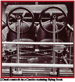 By 1913 improving aeroplane reliability and performance allowed quite daring aerial manoeuvres. Independently of one another, Nesterov and Pegoo flew loops, proving that aircraft were capable of sustaining great loadings in the air. This was the start of aerobatic training which included learning spin recovery skills. A danger to the unwary to this very day, spins are uncontrolled falls at high angles of attack while rolling, pitching and yawing. The number of aerobatic-trained pilots grew rapidly, reaching 30 in Russia alone by early 1914. Thus, despite the greater complexity of aeroplanes and flying, the flight hours per accident indicator improved twenty fold. Whereas in 1909 an accident occurred once every 200 flight hours on average, by 1914 it occurred once every 4000 hours.
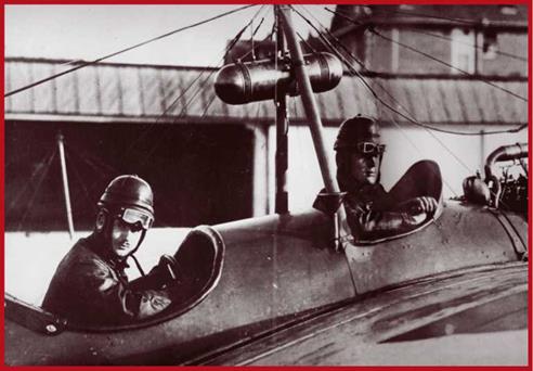
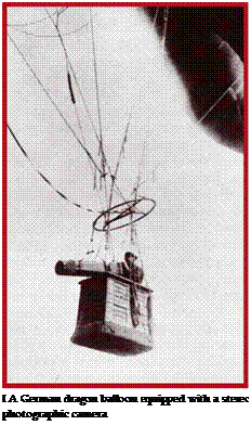 and stronger landing gear, and were easily reconfigured for transportation by road, river or sea. Before impressment into service, such aeroplanes were tested by special acceptance bodies, often on top of having proven their qualities in numerous fly-offs and competitions. This was then a new departure which later found its way to other areas due to its effectiveness.


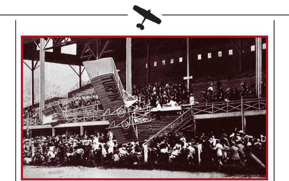
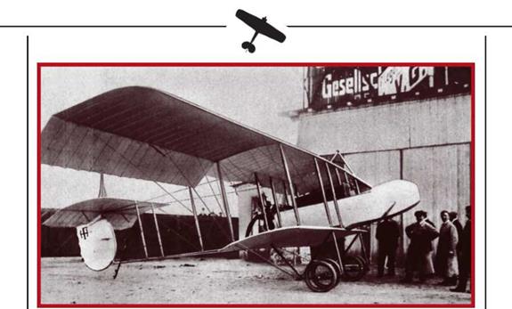
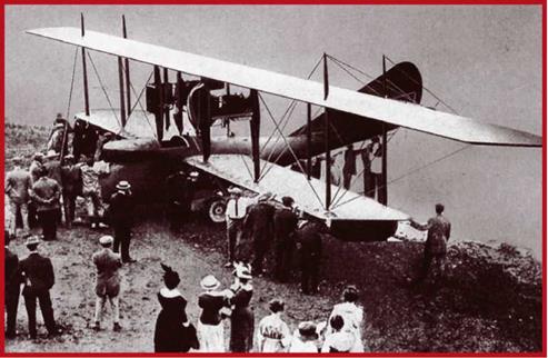
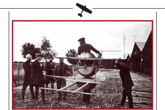
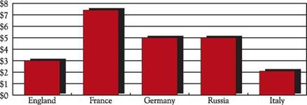
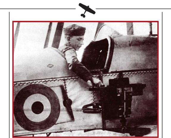
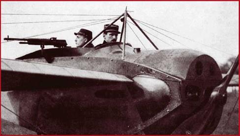
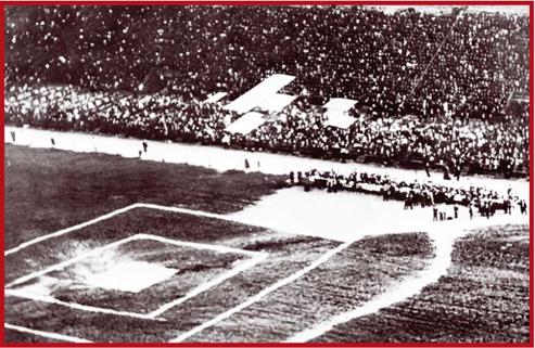
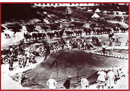
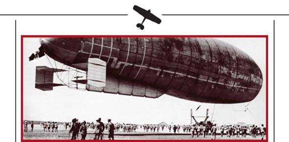

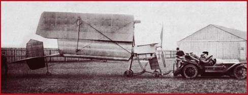
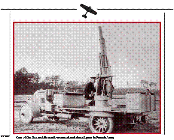
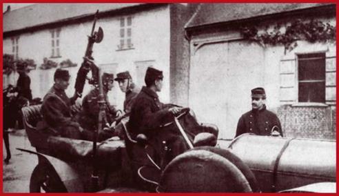
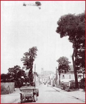


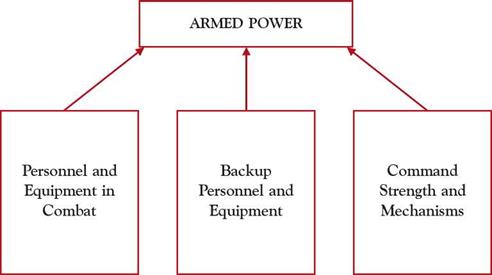

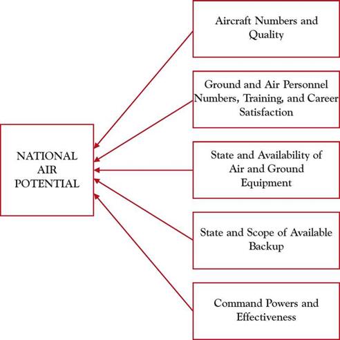

 Kites and rockets later spread to medieval Europe. There is no written confirmation that Europeans used kites to haul men aloft. However, rockets had been tested in battle by the middle of the 15th Century. Though fitted with fins, up until the late 19th Century they were unstable and imprecise, and this inhibited their popularity among soldiers.
 Leonardo formulated principles of lift, and methods of attaining stable controlled flight. In order to increase the sweep of each wing stroke, he employed the combined strength of arms and legs. In his declining years, aware of man’s inadequate and waning physical prowess, the genius directed more attention to fixed wing flying machines. In the closing year of the 15th Century, he devised an ornithopter with partially fixed surfaces, and a technique for gliding during which ornithopter flyers could recoup their strength.
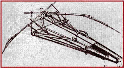


 Dutch scientist and mechanic Cristiaan Huigens (1629—1695) left a wealth of papers. One of his inventions was a pilotless drone with two airscrews spinning in opposing directions and powered by twisted and stretched animal tendons: a prototype of today’s bungee chord-powered flying models. The wings were rectangular and had upturned tips for lateral stability. Hui – gens’ airscrews were the first proposal to use blades for motive power in the air. Their prototypes must have been the innumerable Dutch windmills, which Huigens is known to have studied over an extended period. No record suggests that this drone was ever built and flown, yet the drawing alone is evidence that Huigens overtook developments by over a century.


 lasting eight minutes. After a soft landing four kilometres from the Royal stand, the pioneering Aeronauts were recovered safe. Louis XVI and Queen Marie-Antoinette were impressed and congratulated the Montgolfieres on their success.
 pension awarded him by Jouis XVI on the occasion of overflying the Channel.
 France became embroiled in Revolution and the war against Austria. Meunier was killed near Meinz in 1793. On 14 July the same year, a Convent session approved the use of balloons for military purposes. Means and premises for war balloon production were set aside, with the proviso that sulphur oxide, vital to the artillery, was not to be diverted for hydrogen production. An officer, Jean Coutelle, was put in charge of testing. He managed the task of obtaining large amounts of hydrogen in field conditions brilliantly. The first installation was built near Meudon. Meanwhile, an elastic varnish had been discovered to seal balloons against gas leakage, treated balloons maintaining their shape for two to three months. Tests of the LEntreprenant combat balloon intended for quantity production ended successfully, and in April 1794 the basis of the eventual planned Balloon Division was laid. Initially, it comprised a single Balloon Company. To try out the Eyes in the Sky concept in combat, the Convent ordered Captain Coutelle to Belgium at the disposal of General Jourdain. The latter, and the majority of officers viewed the new arrival with incredulity.


 Another original idea of Loewy’s was to employ river barges as mobile bases for tethered balloons. To assist nocturnal missions, each barge had four navigation lights: iron lamps with their own uninterrupted gas supply. The newly invented telegraph was intended to be used to transmit observation data to the ground. This was first tested in the air on 24 September 1861 at the Battle of Falls Church. To facilitate data simultaneous transmission from several balloons close to one another, one was designated as an airborne base to gather, process and retransmit data. Another innovation in aerial reconnaissance was aerial photography, first practised by Frenchman Felix Nadar in 1858. All this gradually went to construct two basic control effectiveness components of air power: on-board and surface equipment.


 Meanwhile, after building an ornithopter model with P. Go – chault, in 1876 Alphonse Pennault designed and patented a large two seat flying wing monoplane. This was amphibious, intended to depart and alight equally well on water, or on land. Pitch stability was achieved by locating the centre of gravity forward of the wing’s centre of lift. Roll stability was attained by wing dihedral, and longitudinal stability was bestowed by a fin. Controls included an elevator and drag rudders at the wingtips.


 True to intention, the Aeole did indeed look like a bat. This flying wing monoplane with a wing area of almost 28sq m, and 14m span, was made of cloth-covered bamboo.


 those present consider the chances of successful flight very good.


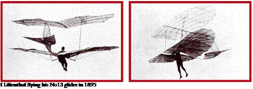


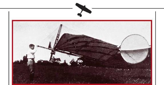


 exceptions, they contained gas bags (ballon – ets) with a combined volume of 11,000cu m. The airship was designed to lift a five-man
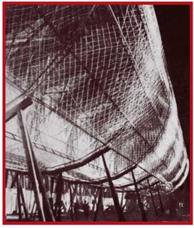

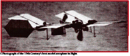
 The scale model flights and the availability of a powerful and light engine raised hopes of success. Regrettably, both flight attempts failed. Pilot Manley got into trouble from which only quick thinking and reflex saved him.
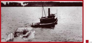

 Despite its inherent conservatism, Britain did not lag behind in the rapid de – velopment of aeronautics at the turn of the Century. Animated discussions were held about the relative merits of lighter versus heavier-than-air craft. Established in 1866, the Aeronautical Society grew


 Soon after receiving the requested literature, he and his brother Orville built a biplane kite. The aim of this first experiment was to test Orville’s contention that birds balance and turn by twisting their wings. The kite had a special control cable which changed wing camber as needed to react to wind direction and speed.
 tion and speed. Most flights were unmanned, the glider flying as a kite. Some tethered flights also took place. Just one piloted glide was flown.

 Successful glides of over a minute’s duration firmly prompted the Wrights to make an aeroplane. The engine installation and propeller were built in the winter and spring of 1902 and 1903. Progress was easy because, as distinct from all their predecessors, the brothers were not aiming at a super light powerplant. All they had to do was adapt a water-cooled four-cylinder petrol engine by stripping away unnecessary road-going complications and weight. It weighted 90kg and developed 12hp: a power to weight ratio of 7.5kg per horsepower, or rather worse than the steam units of the late 19th Century.


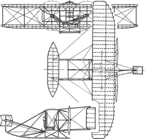


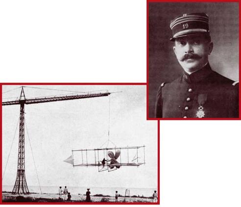 Even the scant attention given to the Wright brothers’ glider trials between 1900 and 1902 stimulated French aeronautics students’ desire to build real aeroplanes. After Lilienthal’s death, European progress in heavier-than-air flying apparatus had come to a standstill. French artillery officer Capt Ferdinand Ferber made the first effort to a resumption. In early 1902, Octave Chanute sent him a copy of the paper on gliding delivered by Orville Wright the previous September. Ferber decided to make a glider similar to that of the Americans, but without the roll control system. He used bamboo and normal timber, and completed the job in 1903. The glider was intended to be powered, and Ferber acquired a 6hp Bouchet internal combustion engine for the purpose, marrying it to two puller propellers. The aeroplane was tested later the same year, being put through its paces while suspended from the gib of an 18 metre high stand. This showed up the engine’s insufficient power: it had to sustain a 235kg machine in flight.
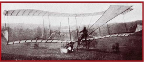
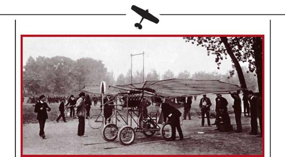
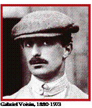
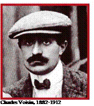 Gabriel Voisin was one of the most famous of pioneer aviators. He was a French mechanic who had designed and built his own gliders. In 1905, he made a float-equipped glider with a strange wing. It took off by being pulled along the Seine by a motor boat, and testing proved that boxing the wing as in a kite resulted in good stability, as well as improving structural strength for a given weight.
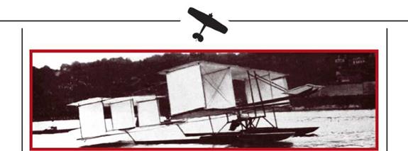
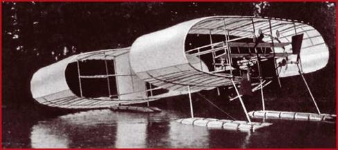

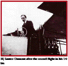 Santos-Dumont began tests in 1906. The Aeroplane was towed behind a dirigible (again designed by himself, hence the bis in the designation). In late August, an attempt was made to fly free, but the contraption failed to get off the ground. Subsequent runups ended in failure. One reason for this was the weak engine, which was changed for a more powerful 50hp Antoinette. The modified aeroplane flew for some 70 to 80m at 3m on 23 October. This was enough for all members of a French Aero Club committee, who witnessed the flight, to admit that Santos – Dumont qualified for the Prix Archdecon, instituted for the first man to fly a distance of not less than 25m.
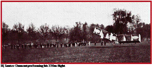
 First trials set tor 28 February 1907 resulted in some successful hops. On 30 March Charles Voisin covered a distance of some 80m. Then the wheeled undercarriage was removed and replaced with floats, but when this did not increase flight lengths, the designers reverted to wheels. On 3 November 1907, Leon Delagrange flew a distance of 500m but crashed on landing.
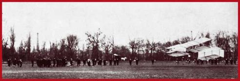
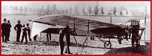
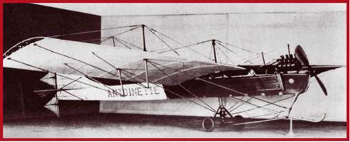
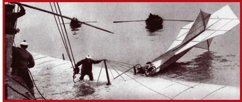

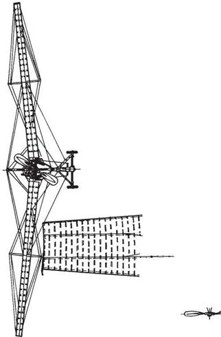
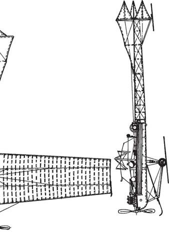
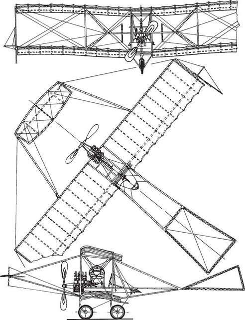
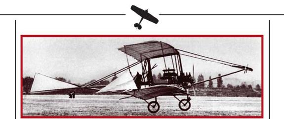
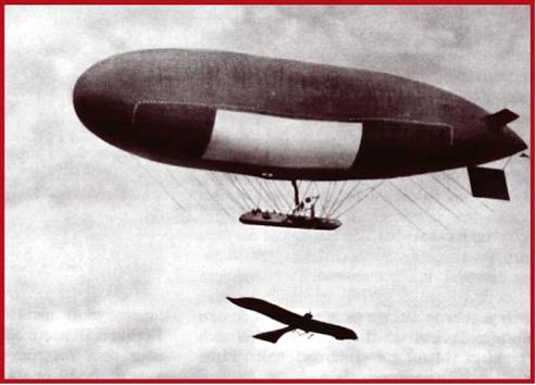
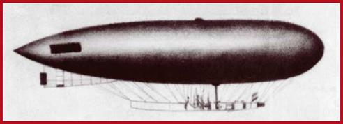
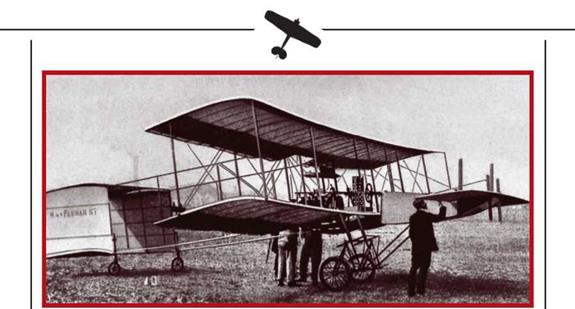


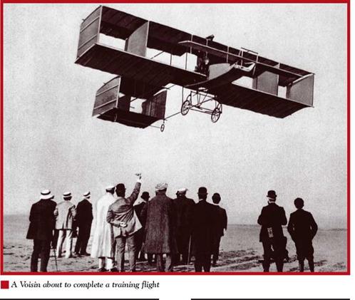

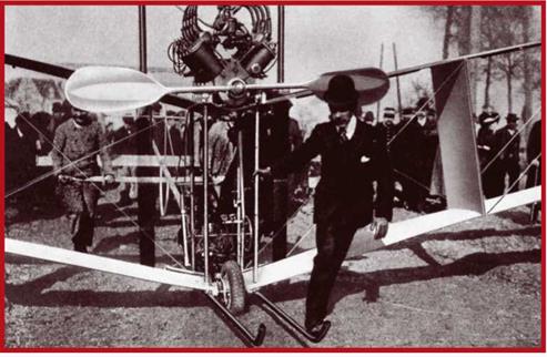
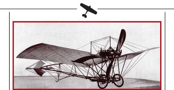
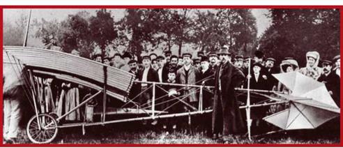

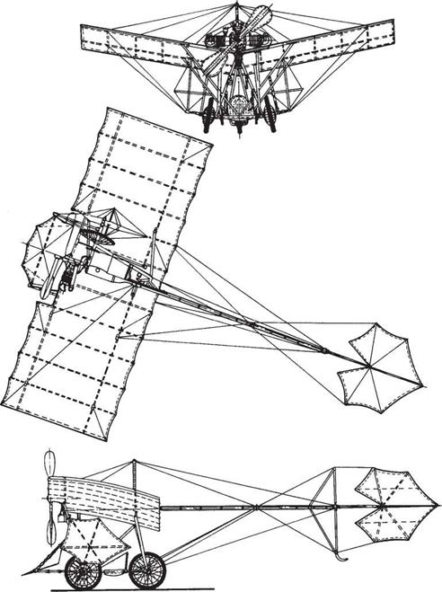
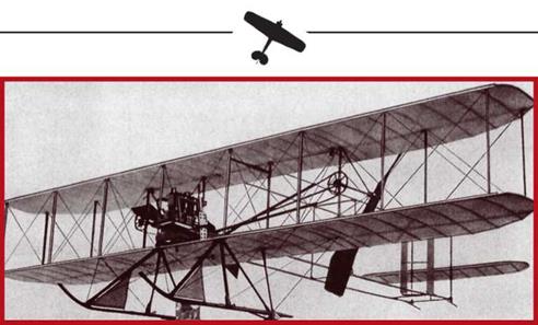
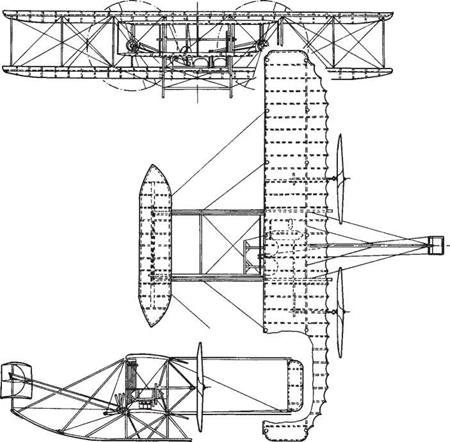
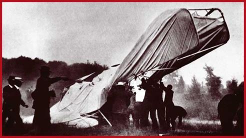

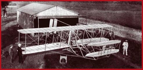

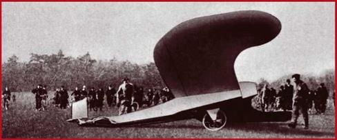
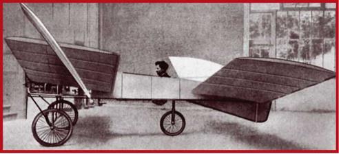
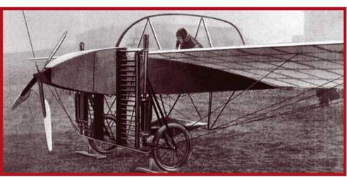
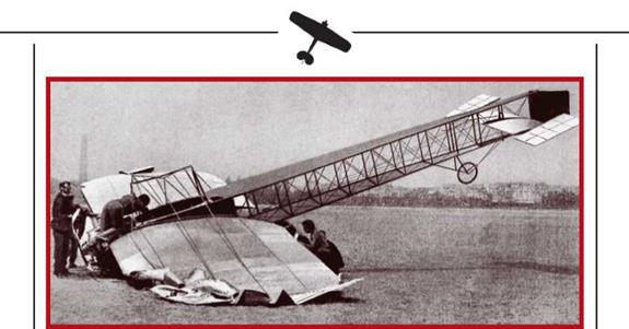
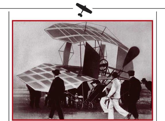
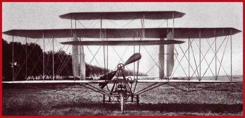
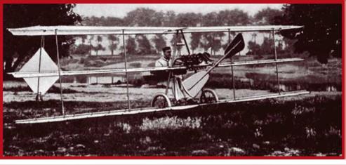
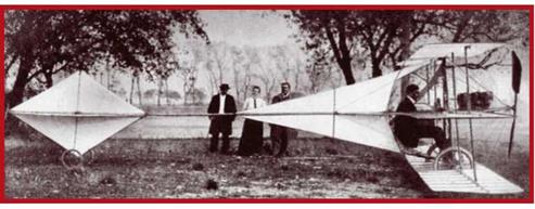
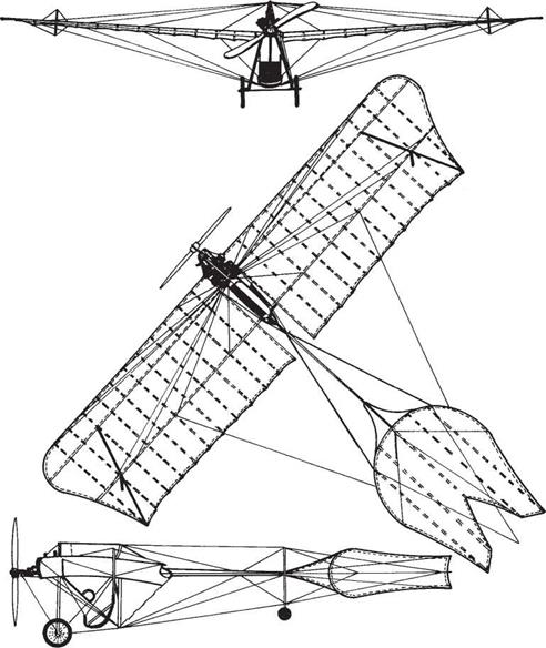
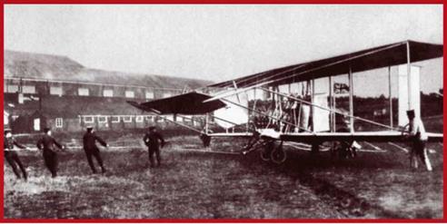
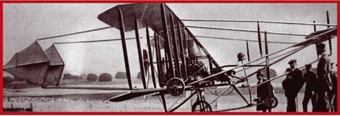
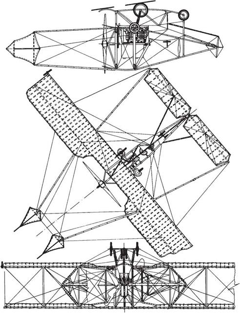

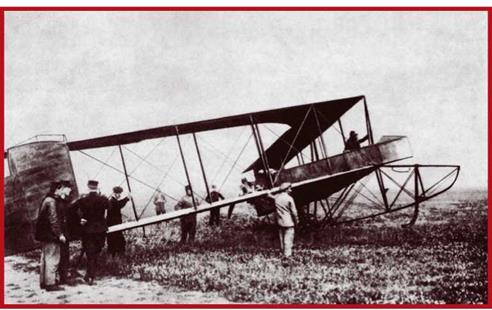
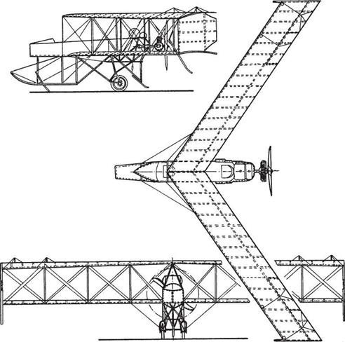
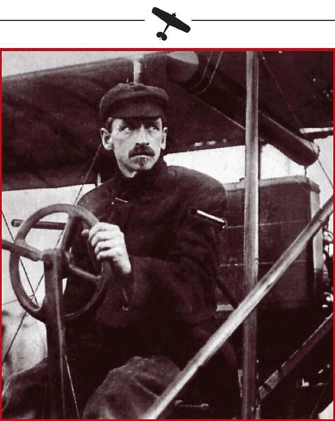
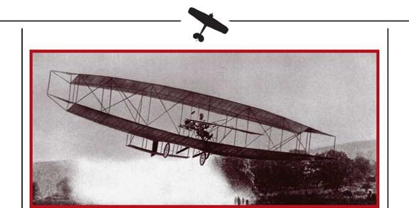


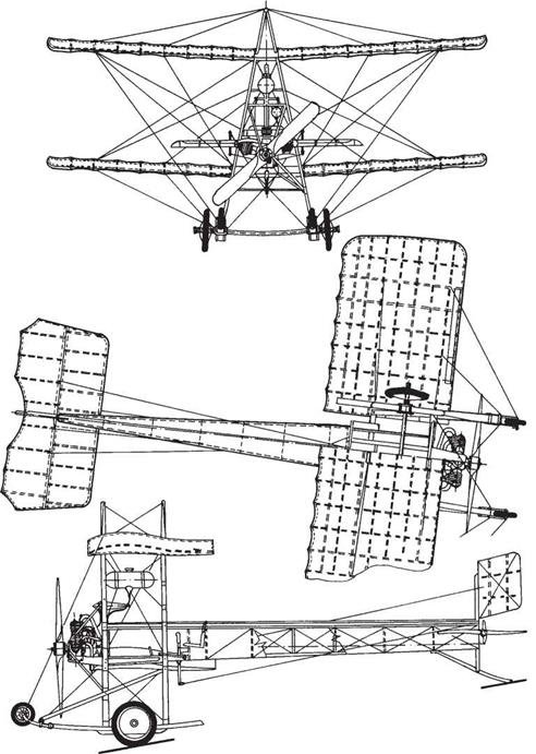
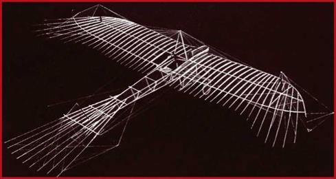
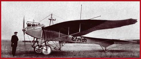
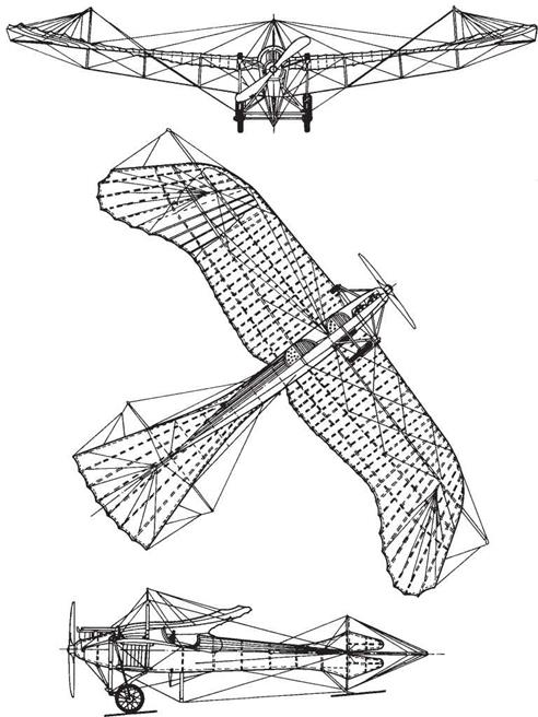
 After the Zanonia flying wing was fitted with a 24hp Antoinette engine driving a two-bladed propeller, and with a twin-wheel undercarriage, it was tested again. Fears that the lack of an empennage would damage controllability were confirmed. An empennage was successfully designed and fitted later the same year, giving birth to the famous ■ The flying seed of the Zanonia plant Taube: most widely used German and Aus – which impressed Alborn trian aeroplane in the 1910 to 1915 period,
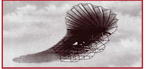
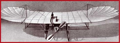

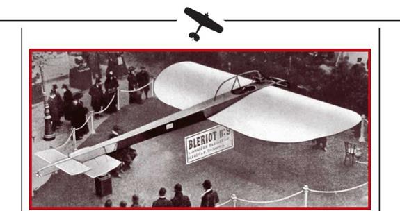
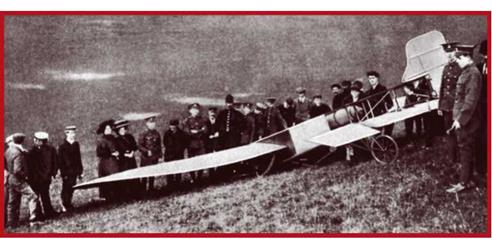

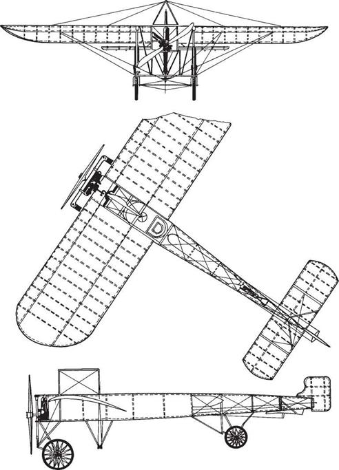
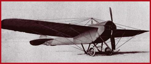
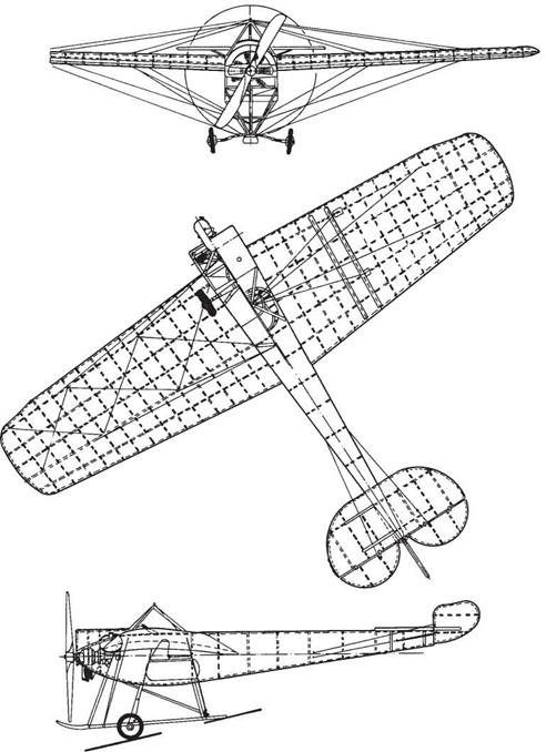
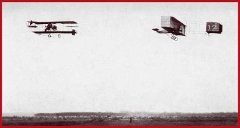
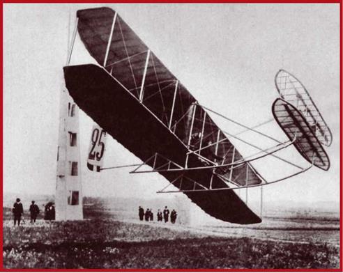
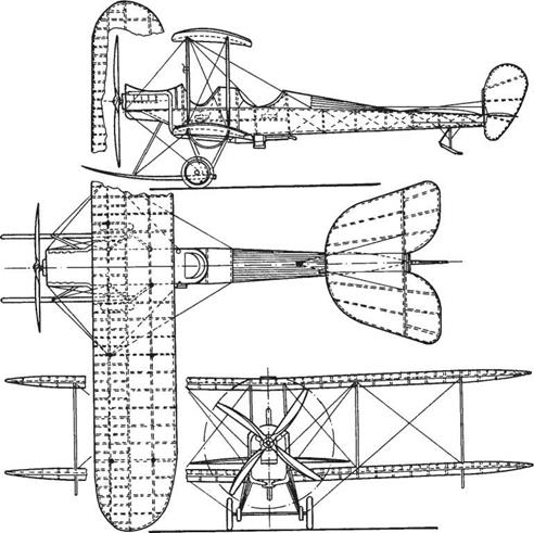
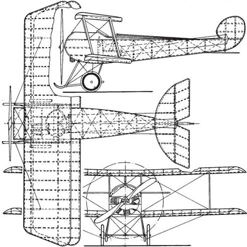
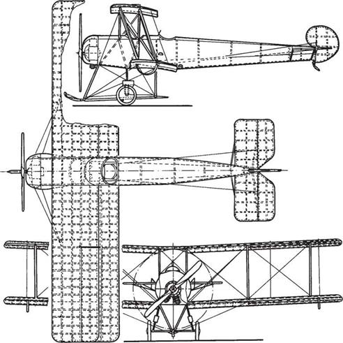
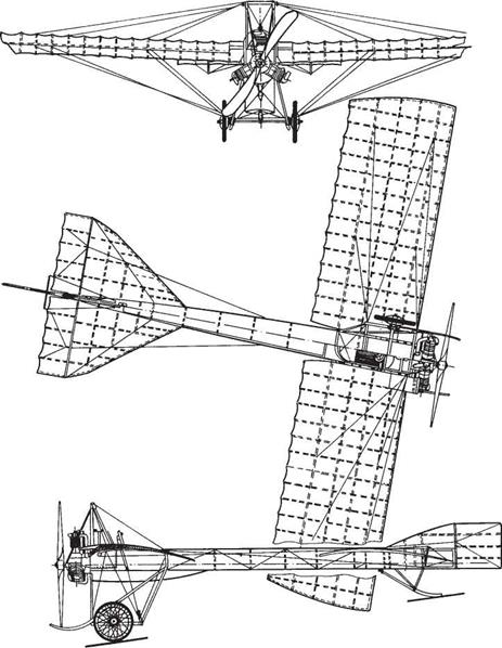
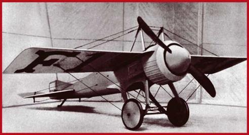
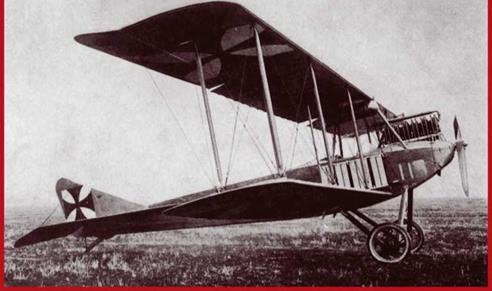

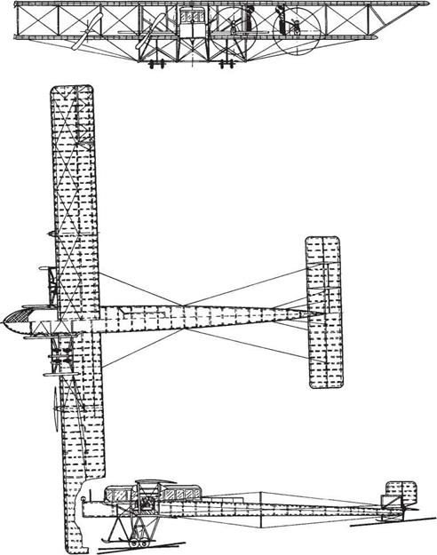
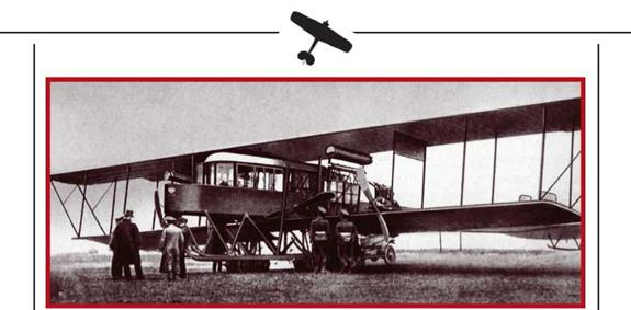
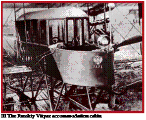 twin tandems, two per lower wng-mounted nacelle. Thus two propellers pulled, while the other two pushed. When it was found that the efficiency of the pusher props was rather low, all four engines were given individual nacelles on the lower wing.