Category SUPERPLANES John Gabriel Navarra

AIRPORTS

An airport complex consists of runways, taxiways, terminal buildings, service areas, hangars, landing aids, and access roads. The aerial view of New York’s La Guardia Airport on the opposite page shows all the parts that make up an airport.

At the top of the photograph, two of La Guardia’s run­ways project on piles over the water of Flushing Bay. Hangars at the left – and right-hand edge of the photo flank the passenger terminal.

A huge five-level parking garage, which accommodates almost 3,000 cars, is in the foreground of the photo. Two passageways connect the parking facility with the central passenger terminal.

La Guardia Airport has a 150-foot-high control tower. The tower is located in the westernmost arcade of the pas­senger terminal at the left of the aerial photo. The control tower—designed in the shape of a flared urn—has twelve working levels.

The success of the airlines in the 1960s caused many problems on the ground: Airport facilities throughout the country were inadequate for the traffic. In the late 1960s, for example, Chicago’s O’Hare Airport was handling 600,000 takeoffs and landings a year—more than one a

minute. Airports serving other major cities also found it difficult to accommodate all the aircraft landing and taking off. During periods of bad weather the problems multi­plied. There were long delays on the ground and in the air!

New and larger airports were built throughout the United States to solve the problems of handling commer­cial flights. Most plans to avoid airport crowding recognize the need to establish a system of airports in and around, major cities. New York City—a city hemmed in by other urban areas—has such a system.

The Port Authority of New York and New Jersey oper­ates Newark Airport, Kennedy International Airport, and La Guardia Airport. Teterboro Airport in New Jersey, which is used for business and private aircraft, serves as a reliever airport. In other words, Teterboro is used to re­duce congestion at the three primary airports. A second reliever airport is operated at Farmingdale, New York.

Newark Airport is located on 2,300 acres of land be­tween the New Jersey Turnpike and U. S. Route 1. The basic plan of the airport can be seen in the aerial photo on the opposite page. The central passenger area consists of three terminal units. Three jet parking areas are attached to each terminal unit. Two of the terminal units with their six jet parking areas were in full operation when this photo was taken. Only two of the jet parking areas at the third terminal unit had been built at this time.

Runways are the areas on which airplanes make their takeoff roll. A runway is also the area on which a landing airplane touches down. The major runways at Newark Air­port are clearly visible in the photo.

Note the two parallel runways just below the six jet parking areas at Newark. These runways stretch for 8,200

feet from left to right across the photo. Can you see that the right-hand end of each of these runways is marked with the number 22?

A runway is marked to the nearest 10 degrees of the compass heading on which it is laid out. The last zero of the compass heading is omitted. Thus, the number 22 on a runway stands for a compass heading of 220 degrees. This means that a plane approaching these parallel runways from the right of the photo is on a heading of 220 degrees. The opposite ends of these runways are marked with the number 4, designating a compass heading of 40 degrees.

There is a third runway at Newark Airport. This third runway, located at the right of the unfinished terminal unit, is numbered 29 at the one end and 11 at the other end. An airplane approaching this runway from the bottom of the photo is on a heading of 290 degrees.

AIR SAFETY

The control tower—standing high above all the other buildings—is an important center of activity at any airport. Rising 177 feet from airfield level, the control tower at Dulles International Airport—shown in the photo below— consists of a concrete shaft. Two stories in the upper sec­tion are used for radar and electronic equipment. The glass-enclosed room on top of the tower is called the cab.

AIR SAFETY

Workers in the tower are called air-traffic controllers. It is their job to direct planes in and around the airport. Large panes of glass in the cab give air-traffic controllers an unobstructed view of the runways and field. The con­troller in the cab—shown in the photo on page 25—is giv­ing directions to a pilot by radio. He is telling the pilot which runway to use.

AIR SAFETY

An air-traffc controller clears the pilot for takeoff. The pilot heads the plane down the runway and into the wind. The engines roar as they thrust the plane forward. Slowly the air flowing past the wings lifts the plane from the ground. Then the pilot points the nose up to gain altitude.

A controller in the tower notes the time the plane took off. This information is sent to the Air Route Traffic Con­trol Center in the area. There are twenty-one centers across the United States.

Each Air Traffic Control Center has a layout that is sim­ilar to the one shown in the photo on page 27. It is the job of the controllers at these centers to keep track of a plane from its takeoff to its landing. The controller shown in the photo on page 26 is using equipment that electronically writes an aircraft’s altitude and identity on the radar dis – p! ay.

AIR SAFETY

The fundamental element in air-traffic control is separa­tion. This means that aircraft are separated laterally, longi­tudinally, and vertically. The lateral or side-by-side separa­tion is maintained by routing aircraft over several parallel airways. The longitudinal or lengthwise separation on an airway is maintained by having a minimum flying time of ten minutes between an aircraft and the one following. Vertical separation is achieved by assigning different alti­tudes to aircraft on the same airway.

Below 18,000 feet, an aircraft on a heading between о degrees and 179 degrees is assigned an odd thousand-foot altitude. For example, an airplane flying eastward on a heading of 90 degrees may be assigned to an altitude of

5,0 feet. On the other hand, an aircraft flying on a head­ing of 180 degrees to 359 degrees is assigned an even thousand-foot altitude. This means that a plane moving

westward on a heading of 270 degrees could be assigned an altitude of 6,000 feet.

Above 18,000 feet, the same system of odd and even thousand-foot altitude assignments is used. The assigned altitudes above 18,000 feet are called flight levels, how­ever. An altitude of 19,000 feet is referred to as Flight Level 190. An aircraft flying at 29,000 feet is at Flight Level 290.

AIR SAFETY
Two sets of rules control the movement of all aircraft in the United States. These federal regulations are known as Visual Flight Rules (VFR) and Instrument Flight Rules (IFR). VFR means that the earth’s surface is clearly visi­ble and the pilot can fly the plane by referring to land­marks. When visibility is poor and weather conditions are producing problems, the pilot controls and directs the air­craft by referring to instruments within the cockpit. Under these conditions, the pilot uses IFR. The prevailing weather over most of the United States and the need to fly along designated airways limit VFR flying.

CARGO OPERATIONS

Cargo is the goods or merchandise carried in a ship, air­plane, or other vehicle. The very first scheduled commer­cial airline flights were set up to carry mail. So cargo has been carried by air since airlines first began operating.

The carrying of cargo did not become a major part of commercial aviation until the 1950s, however. In fact, the first all-cargo air routes were established only in 1949.

Today the world s largest all-cargo airline is the Flying Tiger Line. The first cargo plane used by this company was the Budd Conestoga shown in the photo below. The first cargo carried by the Flying Tiger Line was a plane­load of fresh grapes that was shipped from California to Georgia.

CARGO OPERATIONS
The Conestoga was an all-stainless-steel, rear-loading, twin-engine aircraft. It was capable of carrying 7,000 pounds of cargo over a distance of 500 miles. This rather

CARGO OPERATIONS

cumbersome-looking aircraft had a cruise speed of 150 miles per hour.

The Douglas C-47 shown in the photo above was the cargo version of the famed DC-3. The C-47 was a good re­liable plane. Its performance as a cargo aircraft was better than the Budd Conestoga because it could carry 7,500 pounds of freight over a range of 600 miles at 150 miles per hour. An airline that used the C-47 had a slight com­petitive edge over one that used the Conestoga.

CARGO OPERATIONS

The C-54 was the first of the four-engine airfreighters. In the photo below, cargo is being moved into a C-54 along an airfreight dock at Burbank, California. Flying at 210 miles per hour, a C-54 could carry 20,000 pounds of cargo over a 2,000-mile range. In the late 1940s, a fleet of C-54S flew from the United States to Tokyo on an eight – flight-per-day schedule for almost a year to supply the American Occupation Forces in Japan.

CARGO OPERATIONS

The Lockheed Super H Constellation is shown above. This plane was put into service in 1957. It could airlift.

43,0 pounds of freight at 300 miles per hour. The Super H Constellation had the first true coast-to-coast nonstop range of 2,500 miles. Transcontinental airfreight schedules were revolutionized by this plane.

The design of cargo aircraft evolved along with the growth of the freight business. And in 1961, the first tur­bine-powered airfreighter, Canadair CL-44, shown below, was placed in service. The CL-44S unique swing-tail de­sign permitted straight-in loading of up to 65,000 pounds of freight. This airfreighter cruised at 375 miles per hour over a range of 3,000 miles.

CARGO OPERATIONS

The DC8-63 was the first of the jumbo-jet airfreighters. This sleek giant—shown at the top of the opposite page – carries a payload of 110,000 pounds at 550 miles per hour over a 3,000-mile range. Today major markets of the United States and Asia are linked by these huge air­freighters.

CARGO OPERATIONS

There is a continuing need for greater cargo capacity in world-wide airfreight operations. Wide-bodied aircraft like the Boeing 747 have large volume capacities. Boeing has built some 747s to carry freight.

CARGO OPERATIONS

The Flying Tiger Line uses some of Boeing s awesome giants to carry cargo to world-wide markets. The 747 air­freighter and its interior are shown below. This giant can carry 200,000 pounds of cargo at 575 miles per hour over a 3,500-mile range.

SUPERSONIC TRANSPORTS

Sound travels at about 760 miles an hour through the at­mosphere. Aircraft that move faster than sound are said to be supersonic. Today supersonic transports—called SSTs— streak through the sky at more than twice the speed of sound.

The term Mach number is used to report the speed of an airplane. A Mach number is a measure of an aircraft’s speed in relationship to the speed of sound. The speed of sound is given a Mach number of one.

An aircraft moving at twice the speed of sound is said to be flying at Mach 2. A Machmeter is shown in the lower photo on the opposite page. The Machmeter is in the pas­senger cabin of a Concorde—the first SST. The meter indi­cates that the plane is flying at Mach 2.04, which is more than twice the speed of sound.

The Concorde is shown in the upper photo. It can carry 108 passengers with a total payload of 25,000 pounds. Concorde burns somewhat less fuel to fly across the Atlan­tic Ocean than a 747, and it can fly over a range of 4,000 miles. The plane is designed to cruise at Mach 2. The alti­tude at which the Concorde normally flies is between

50,0 and 60,000 feet.

SUPERSONIC TRANSPORTS

The nose of the Concorde is lowered to improve the pilot’s visibility at takeoff and landing. The Concorde’s nose droop can be seen clearly in the photo below taken during a landing at Washington’s Dulles Airport. Dulles Airport is sometimes referred to as “The Airport of the Fu­ture." It was designed to handle aircraft like the Concorde.

The wings of the Concorde have a very special shape. They are shaped like the Greek letter delta, which looks like a triangle. For this reason the Concorde is called a delta-wing SST.

SUPERSONIC TRANSPORTS
A delta-shaped wing gives an SST some advantages. The large surface area of the wing produces a cushion of air

SUPERSONIC TRANSPORTS

below it. The cushion of air makes it impossible to stall the plane while landing. And it allows the pilot to land the plane safely at relatively low speeds. The landing speed of the Concorde is about 180 miles per hour.

An SST can move faster than the speed of sound. When one does, it outraces its own sound and produces a boom. A sonic boom is simply a strong pressure wave. It is pro­duced by two cones. One cone forms at the nose and the other forms at the tail of the SST. A boom carpet, shown in the picture above, spreads across the earth when the cones reach the ground. The width of Concorde’s “boom carpet” is about 50 miles.

A sonic boom is not produced until an aircraft is flying faster than Mach 1, the speed of sound. Thus, at subsonic speeds Concorde is just like any other airliner and it makes no boom. This fact is used to control the boom produced by the Concorde.

On takeoff, the Concorde becomes airborne at a speed around 200 miles per hour. The takeoff speed, of course, depends on the aircraft’s weight and how heavily it is

loaded. Thus the Concorde takes off and lands in a normal manner at low speeds that produce no boom.

The acceleration to supersonic speeds is delayed after takeoff until the plane is safely over the ocean and away from inland and coastal cities. When Concorde approaches a coastal area such as New York, for example, it decel­erates to subsonic speeds. In fact, Concorde begins flying at low speeds over the ocean at least 100 miles from land. The subsonic speeds produce no booms.

At supersonic speeds a plane’s skin gets hot. The heat is generated by the passage of air over the outer surface of the aircraft. A supersonic transport needs an air-condition­ing system to maintain a comfortable temperature in the passenger cabin.

The Concorde has a specially designed air-conditioning system that maintains a uniform cabin temperature. During the landing descent at subsonic speeds, Concorde’s skin cools down. The outer surface is not warm to the touch after the plane lands.

Supersonic transports can reduce the travel time be­tween all major cities in the world. The Concorde travel time between New York and London is three and one-half hours. At present subsonic speeds, New York is seven hours from London. The trip from Los Angeles to Hono­lulu by subsonic jet takes just over five hours. The Con­corde cuts this travel time in half. A trip from San Fran­cisco to Melbourne, Australia, takes almost nineteen hours by subsonic jet. The Concorde puts San Francisco within nine and one-half hours of Melbourne.

SUPERSONIC TRANSPORTS


SUPERSONIC TRANSPORTS

SUPERSONIC TRANSPORTS

Military Aircraft

The aircraft developed and used by our armed forces are the vehicles of aerial warfare. The function for which an aircraft is designed dictates its size, shape, speed, range, weight, and its operational altitude. Our armed forces have a need for many different kinds of aircraft.

The easiest way to classify military aircraft is by the job that they are designed to perform. There are, for example, aircraft used for training, observing, fighting, bombing, trans­porting, rescuing, and air refueling. In the sections that follow you will find some examples of modern military fighter, bomber, transport, and reconnaissance aircraft.

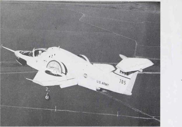
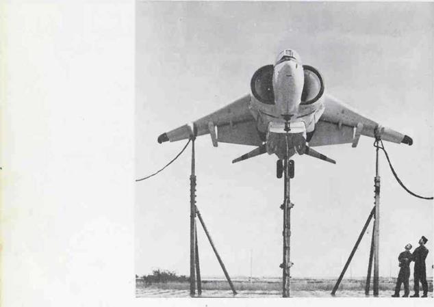
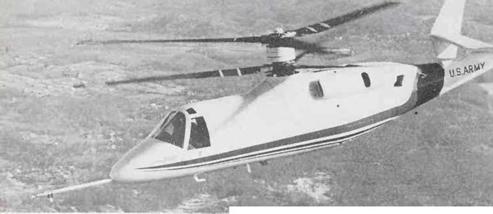
Another important part of military aviation is the devel­opment of new aircraft. It takes a lot of money, time, and patience to develop a new idea that eventually becomes an operational aircraft. In the next few pages you will find a description of three experimental aircraft that have been used to good advantage by our armed forces.

THE EXPERIMENTALS

The United States Government approved a Research Air­plane Program in 1944. The first in the series of pure research aircraft, the X-i, was launched in 1946. The “X” in the name of the plane means experimental.

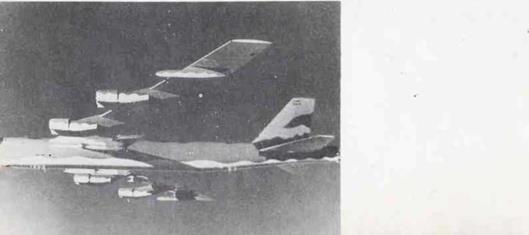
The X-15, shown in the photos, is a small rocket-pow­ered aircraft. On June 8, 1959, the X-15 made its first flight after being dropped from the protective wing of a B-52. In a decade of flight that ended in 1969, the X-15 reached heights and speeds that are still unmatched by any other aircraft. The X-15, f°r example, reached a peak altitude of more than sixty-seven miles. And on October 3, 1967, an X-15 was flown at a speed of 4,520 miles per hour, which is the equivalent of Mach 6.7.

At heights of sixty-seven miles, the X-15 was traveling above the effective atmosphere. Thus, the X-15 collected information on flights in air and space. By flying to the frontiers of space, the X-15 tested the effects of weight­lessness on human pilots. The X-15 research program also demonstrated the ability of human pilots to fly high-pow­ered aircraft with great accuracy.

THE EXPERIMENTALS

/


*


THE EXPERIMENTALSTHE EXPERIMENTALSTHE EXPERIMENTALSTHE EXPERIMENTALS

THE EXPERIMENTALS
Another research superplane, the XB-70, is shown taking off from Edwards Air Force Base in California. Two of these planes were developed and built for the Air Force. The XB-7o’s delta wing has a span of 105 feet. The fuse­lage is 185 feet long and 30 feet high.

The XB-70 has a long, pencil-like nose. Stubby horizon­tal stabilizers are located on each side of the plane just behind the cockpit. In the photo you can see the shadow cast by a stabilizer. The shadow reaches to and below the E in the word FORCE.

The delta wings of the XB-70 extend all the way to the tail section of the plane. Twin vertical stabilizers rise from the rear of the wings. Below the wings the exhaust pipes of the plane’s six engines can be seen.

The XB-70 has a range of 7,500 miles. It was designed to fly above 70,000 feet at speeds of 2,000 miles per hour, which is equivalent to Mach 3. The plane was used exten­sively to study the stability, control, and handling charac­teristics of large supersonic aircraft.

The YF-12A is shown in the photo below. This plane is an experimental long-range interceptor that was nicknamed the Blackbird, It was developed for defense against supersonic bombers and airborne missile launchers. The Blackbird flies above 80,000 feet at a speed of Mach 3, which is more than

2,0 miles per hour.

The Air Force and the National Aeronautics and Space Administration (NASA) are using the YF-12A in a joint research program. An important part of the program is concerned with flight management and air-traffic control. The researchers are studying the ability of the plane to maintain a precise altitude at supersonic speeds.

RECONNAISSANCE

The original function of military aircraft was recon­naissance, that is, observation of enemy territory and posi­tions to gather information. Most observation aircraft are of comparatively light weight and small size. They carry one or two observers and sufficient communication equip­ment to report their observations.

A Lockheed U-2 is shown in the photo on the opposite page. This aircraft is a subsonic turbojet that flies very – high-altitude reconnaissance missions. The plane is used by the National Aeronautics and Space Administration (NASA), the Central Intelligence Agency (CIA), and the United States Air Force (USAF). The wing size and its placement give the U-2 the appearance of a powered glider.

There is a large air intake at the wing root on each side of the plane. These air intakes make the U-2 look like a twin-engined plane. But both intakes feed into a single en­gine. The U-2 cruises at about 450 miles per hour. It has a maximum speed of 528 miles per hour.

The U-2 has a wingspan of 80 feet. The plane is almost 50 feet long and stands 13 feet high at the tail. It is a light airplane for its size and weighs less than 16,000 pounds at takeoff. The U-2 has a range of more than 4,000 miles, and it can operate at altitudes of 70,000 feet.

The U-2 was involved in a major international incident in i960: On May 1, a U-2 operated by the Central Intelli­gence Agency entered Russian air space from the direction of West Pakistan. A Russian surface-to-air missile inter­cepted the U-2 at an altitude of 68,000 feet. The U-2 was shot down about 1,000 miles east of Moscow. This incident involving the U-2 was responsible for some difficult times in the United States-Russian relations during the early 1960s.

FIGHTERS

A modern fighter aircraft is smaller than a bomber or a transport. But it is far from being a small airplane. It must be large enough, for example, to carry sufficient fuel to ac­complish its mission and return to its base. A modern fighter must also carry a heavy payload of cannon, air-to – air missiles, rockets, and guns.

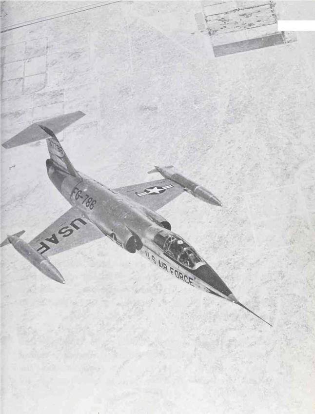
A Lockheed F-104 Super Starfighter is shown in the photo on the next page. This plane has a speed of better than Mach 2. The Starfighter can operate at altitudes above 100,000 feet. An F-104 can climb as fast as it flies straight and level.

The F-104 has stubby knife-thin wings and a high T – shaped tail. From nose to tail the Starfighter measures 54 feet, 9 inches. It stands 13 feet, 6 inches high and has a wingspan of 21 feet, 11 inches.

Some F-104S are assigned to the Air Defense Command. These Starfighters are being used as air-defense fighters. This means that they are designed and equipped for attack against enemy bombers that are unprotected by enemy fighters. Thus, an air-defense fighter carries rockets. Radar equipment on board is used to find the enemy aircraft and aim the rockets at the incoming bombers.

FIGHTERS

FIGHTERS

FIGHTERSFIGHTERSFIGHTERSFIGHTERS

An F-шА is shown in the photo above. This plane is a tactical fighter. As a tactical fighter its mission may involve an air attack on enemy ground forces or positions. Such an aerial attack is often undertaken in close support of friendly ground forces.

The F-111 was developed by General Dynamics in 1964. Two basic models were put into service in 1967: the F-111A and the F-111B. The F-111A is used as a tactical fighter by the U. S. Air Force. The second model, the F-111B, is operated from the decks of aircraft carriers by the U. S. Navy.

Two other types of F-ins using the same basic design have been built: the RF-шА and the FB-111. The RF – 111A is a reconnaissance fighter. And the FB-111 is a stra­tegic bomber.

The F-111 is a variable-wing aircraft. This means that its wings can be moved into various positions. When a slow takeoff is desired, the wings are extended or placed in a position that is almost perpendicular to the fuselage. In flight, the variable-sweep wings can be folded or swept back into a triangular or delta configuration. The delta configuration is used when very high speeds are desired at both low – and high-flight altitudes.

The wings are usually extended during takeoff and land­ing. The extended or perpendicular position with a wing­span of 63 feet provides maximum lift. When the wings are extended, less than 3,000 feet of runway are required for takeoff and landing. The position of the wings shown in the photo of the F-111A is an intermediate angle be­tween the perpendicular and the delta positions. In the delta position, the wingspan is a mere 32 feet.

The F-111 is a 72-foot-long supersonic aircraft. It has a maximum speed of Mach 2.5 at 60,000 feet. The F-111 has a range of 5,000 miles without refueling. This means that it can be sent on transoceanic missions. In addition, how­ever, this aircraft is equipped so it can be refueled in flight.

The F-111 is equipped to carry both conventional and nuclear weapons. Its armament includes air-to-air missiles, air-to-ground missiles, and rockets.

BOMBERS

Modern bomber aircraft are streamlined giants. They are equipped with the best jet engines, which produce speeds that compare favorably with fighter aircraft. Bombers nor­mally have extensive ranges. And when a bomber is equipped for aerial refueling, it has a virtually unlimited range.

The Boeing B-52 Stratofortress is the last of the so – called “conventional bombers/’ The first B-52 was flown in April 1952. The last Stratofortress came off the production line in 1962.

The B-52 was designed as a nuclear bomber. Its belly is divided into two separate bomb bays to carry two nuclear weapons. As many as twelve Short Range Attack Missiles (SRAM) can be carried externally under the wings.

BOMBERS
The last of the B-52S built has a wingspan of 185 feet. From nose to tail, the plane is 160 feet long. The B-52 is

powered by eight jet engines that push it through the air at 650 miles per hour. Its unrefueled range is more than

6,0 miles, and the plane normally flies above 50,000 feet.

The Stratof or tress carries a crew of six. There are two pilots, a navigator, a radar bombardier, an electronic coun­termeasures officer, and a fire-control director who sits in the forward section of the aircraft. The tail guns are trained through the use of radar that is mounted in the tail.

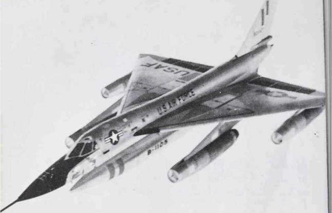
A Convair B-58 Hustler is shown above in the process of completing an aerial refueling. The B-58 is a Mach 2 bomber that was first flown on November 11, 1956. The Hustler was the first supersonic bomber in the world.

The B-58 with an overall length of 97 feet is much shorter than the B-52. The B-58S delta wing spans almost 57 feet. The delta-wing design of the B-58 requires that all takeoffs and landings be made at high speeds. The takeoff speed of a B-58 is often above 230 miles per hour. Its landing speed is as high as 190 miles per hour.

BOMBERS
The B-58 shown above carries a three-man crew consist­ing of the aircraft commander, bombardier navigator, and the defense-systems operator. The entire wing and most of the fuselage behind the cockpit are used to store more than fifty tons of fuel. The weapons payload—18,000 pounds of bombs—is carried beneath the aircraft in a long pod. The pod can be seen in the photo; it is numbered B-1105.

A photo of the B-i strategic bomber is shown on page 53. This aircraft was developed by the Air Force to mod­ernize its bomber fleet. The first flight of a B-i took place on December 23, 1974. A rather extensive flight test pro­gram was developed by the Air Force for the B-i.

The В-1 is a variable-wing bomber. In the extended or forward position the wingspan is 135 feet. In the folded or swept-back position the wingspan is 78 feet. The swing wing allows the B-i to perform efficiently at low and high speeds.

At low, slow speeds a straight wing is much more efficient than a swept wing. During takeoffs, landings, air­borne loiter, and aerial refueling there is a distinct advan­tage to being able to place the B-Ts wings in a straight or forward position.

Four powerful jet engines give the 150-foot-long B-i a top speed of Mach 2.1, which is approximately 1,350 miles per hour. For high-speed supersonic flight at both low – level and high altitudes, there is a definite advantage to having the wings in a swept position.

TRANSPORTS

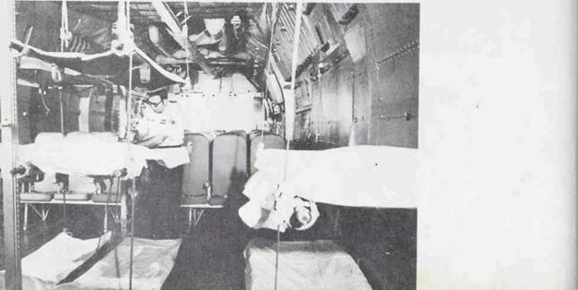
A military air transport is an aircraft designed for the movement of cargo and passengers. Transports usually have the capability of being modified so they can be used for special missions. For example, the photo below shows the interior of a C-141 modified to provide litters, oxygen equipment, and the facilities necessary for the air evacua­tion of wounded.

TRANSPORTS
A Lockheed C-141 Starlifter is shown in the photo on the opposite page. The Military Airlift Command began using these planes in 1963. The C-141 has a maximum takeoff weight of around 320,000 pounds. Today the C-141 is used primarily for carrying troops.

TRANSPORTS
The C-141 has a 145-foot fuselage. It has a wingspan of 160 feet. The T-tail stands 39 feet high. The C-141 has four fanjet engines. Each of the engines develops 21,000 pounds of thrust, which allow the C-141 to cruise at more than 500 miles per hour.

The C-141 can carry troops in airline-type seats. Study the photo of the C-141 interior on the opposite page. There are seven rows of airline-type seats behind the lit­ters.

The C-141 was the first pure jet aircraft specifically de­signed and built to meet military standards as a troop and cargo carrier. This four-engine, T-tailed jet regularly flies nonstop from Dover Air Foce Base in Delaware to Ger­many. It can fly nonstop from San Francisco to Tokyo.

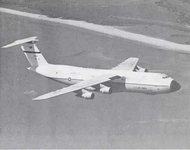
The gigantic С-5 Galaxy, put into service in 1970, is modeled after the C-141. But it is much larger than the C-141. The C-5, for example, has a maximum takeoff weight of 760,000 pounds. This is almost two and one-half times greater than the C-141S takeoff weight.

The C-5 is just about 248 feet long. It has a wingspan of almost 223 feet. The T-tail of the C-5 reaches 65 feet into the air.

The C-5 has unique front and rear cargo openings. The visor-nose opening at the front of the plane can be seen in the lower photo on the opposite page. The cargo compart­ment is 121 feet long, 13.5 feet high, and 19 feet wide. The C-s’s cargo floor area is triple that of the C-141 Starlifter. And the volume of the C~5’s cargo hold is four and one-half times larger than that of the C-141.

The C-5 does not carry troops in the cargo compart­ment. The second story or upper deck, however, has sev­enty-three seats that are in a rear compartment. Drivers and operators of equipment being airlifted use the seats available in the rear compartment on the upper deck. The forward compartment on the upper deck has accommo­dations for a six-man crew, a six-man relief crew, and eight couriers. The flight deck, of course, has the work sta­tions for the crew.

Four jet engines are mounted on pylons beneath the wing. The average cruise speed of the C-5 is 520 miles per hour. The Galaxy flies above 35,000 feet and has a range of 6,300 miles with 100,000 pounds of cargo. The maxi­mum load it can carry is 255,000 pounds.

TRANSPORTS

TRANSPORTS

TRANSPORTS

TRANSPORTS