Category Mig

MiG-19 / SM 9/1

After the failure of the SM-2, the only way for the project to move for­ward was to equip the AM-5F turbojet with a modified afterburner. Once modified, the engine was named the AM-9 В (AM-9 being its pre­liminary design designation). Its dry thrust was now 2,550 daN (2,600 kg st), rising to 3,185 daN (3,250 kg st) when reheated and 6,370 daN (6,500 kg st) when paired—a figure that met the needs of the OKB engi­neers, Two test engines were installed in the SM-2B airframe. With these two AM-9Bs and a few modifications of the fuselage to accommo­date the new afterburners and protect the structure from high temper­atures, the SM-2B became the SM-9/1. The development of this aircraft was ordered by decree no. 2181-887 of the USSR council of ministers, dated 15 August 1953.

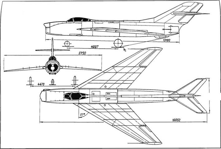
All flight controls were boosted, and the nonrotating tailplane was fitted with an elevator. The midwing sweepback C/4 was 55 degrees.

image199

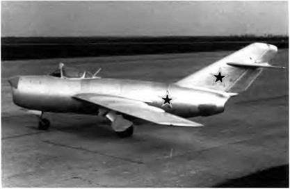
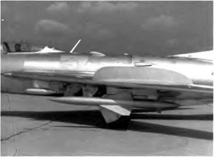
The air probe on the SM-9/1 could be hinged upward to avoid any damage that could be caused by ramp vehicles.

and the stabilizer sweep was 55 degrees at the leading edge. The cock­pit was pressurized and air-conditioned with cold – and hot-air bleeds from the engine. The temperature inside the cockpit remained uni­form thanks to a special temperature regulator with an automatic dis­play. The ejection seat was of the curtain type, a device that protected the pilot’s hands and face when ejecting at high speeds. The tail chute was housed in a canister under the rear fuselage. Armament consisted of three NR-23 cannons, two in each wing root and one on the lower right side of the fuselage.

The team in charge of the SM-9 tests was G. A. Sedov, chief pilot, V. A. Arkhipov, chief engineer, and V. A. Mikoyan, Arkhipov’s assis­tant. The new engines were monitored by two specialists from the Mikulin ОКБ, 1.1. Gneushev and V. P. Shavrikov. The SM-9’s first flight took place on 5 January 1954 with Sedov at the controls. During that flight the engines ran smoothly but the afterburners were not used. The pilot found the aircraft easy to handle and capable of supersonic speed. During the second flight Sedov lit up the afterburners and broke the sound barrier, a procedure that he repeated many times in the course of the tests. On 12 September 1954 the factory tests ended; on 30 September the state acceptance trials commenced.

The SM-9 was clearly an aircraft with a future The official test report made the point this way: "The SM-9/1 ’s performance data are far better than those of the MiG-17F. The former is 380 km/h [205 kt]

image200

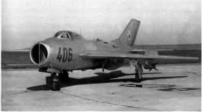
The main features of the SM-9/1 are its Fowler-type flaps, fixed stabilizer with eleva­tors and deep-chord wing fences.

image201

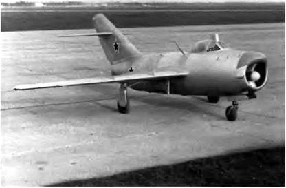
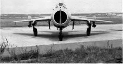
This photograph was taken before the wing-root cannons were installed. Their place was occupied by a provisional fairing.

faster at 10,000 m [32,800 feet], and its service ceiling is 900 m [2,950 feet] higher." This report, approved by Marshal Zhigarev, the air force commander-in-chief, recommended the SM-9 (designated the MiG-19 by the military) for its units.

Well before the end of the state trials, the council of ministers issued decree no. 286-133 on 17 February 1954 ordering the mass pro­duction of the MiG-19 in two factories, one in Gorki and the other in Novosibirsk. Initiating a rather uncommon procedure, the council of ministers ordered the ministry of aircraft production to build (and the ministry of defense to accept) the first fifty aircraft and the first hun­dred turbojets from the design office blueprints and not, as was cus­tomary, from the production sets of drawings, because the latter were not yet ready. The first MiG-19s were delivered to the air force in March 1955.

Performance

Max speed, 1,451 km/h at 10,000 m (784 kt at 32,800 ft); max speed at sea level, 1,150 km/h (620 kt); climb to 10,000 m (32,800 ft) in 1.1 min; to 15,000 m (49,200 ft) in 3.7 min; service ceiling, 17,500 m (57,400 ft).

1-410 / I3U /15

The I-3U was a revised and corrected edition of the 1-3. Its role was to intercept and destroy hostile aircraft at any speed and altitude and in any weather conditions. It differed from the basic aircraft in its auto­matic flight management and fire control systems. The latter, called the Uragan-1, included the Almaz ranging radar, the OKB-857 comput­er, and the AP-36-118 autopilot. The radar range was 17 km (10.5

image232

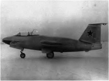
The I-3U/I-5 was equipped with the Almaz ranging radar, housed in an off-center nose cone.

image233

The cockpit canopy of the I-3U/I-5 was hinged to open upward and forward—an arrangement retained on the first-series MiG-21s.

252

и

miles). The fighter was led to its target by ground stations. The main airborne systems included the ASP-5M gunsight, the ARK-5 automatic direction finder, the MRP-48 marker receiver, IFF interrogator, and radar warning receiver (RWR). Armament consisted of two NR-30 can­nons with 65 rpg located in the leading edge near the wing root; the aircraft could also carry two rocket pods with a total of sixteen ARS-57 rockets.

Like the 1-3, the I-3U was a victim of its disappointing engine. The ill-fated VK-3, which was supposed to deliver a dry thrust of 5,615 daN (5,730 kg st) and a reheated thrust of 8,270 daN (8,440 kg st), never did live up to expectations. Because no other turbojet in that category was available, the I-3U, rolled out in 1956, never left the ground. This explains why only design performance data are given

Specifications

Span, 8 978 m (29 ft 5.5 in), overall length (except probe), 15 785 m (51 ft 9.5 in); fuselage length (except cone), 13.54 m (44 ft 5 in); wheel track, 4.036 m (13 ft 2.9 in); wheel base, 5.35 m (17 ft 6.6 in); wing area, 30 m2 (322.9 sq ft); empty weight, 6,447 kg (14,210 lb); takeoff weight, 8,500 kg (18,735 lb); max takeoff weight, 10,028 kg (22,100 lb); fuel, 1,800 kg (3,970 lb), wing loading, 283.3-334.3 kg/m2 (58-68 5 lb/sq ft), max operating limit load factor, 8

Design Performance

Max speed, 1,610 km/h at 5,000 m (870 kt at 16,400 ft); 1,750 km/h at

10,0 m (945 kt at 32,800 ft); climb to 5,000 m (16,400 ft) in 0.47 min; to 10,000 m (32,800 ft) in 1.12 min; service ceiling, 18,300 m (60,000 ft); landing speed, 210 km/h (113 kt); endurance, 1 h 28 min, range, 1,290 km (800 mi); takeoff roll, 560 m (1,840 ft); landing roll, 580 m (1,900 ft)

1420 / I-3P

This preliminary design did not come to fruition as planned It was an interceptor version of the 1-3, but while it was being built it was con­verted into an I-3U equipped with the Uragan-1 flight management and fire control system.

IV»iG 21F13 / Tip 74

The MiG-21 F-13 was the first production MiG-21 armed with K-13 air-to-air missiles, hence its designation. After it was accepted by the air force, the K-13 was renamed R-3.

and the bracket for the gear leg hinge was placed at the juncture of those two spars

3. A rear spar preceded by ten ribs that were set parallel to the fuse­lage datum line, and a rear false spar

The rear wet wing tanks were located between rib nos. 1 and 6. The upper and lower walls of the fuel tanks were made of machined plates of the V-95 alloy, the same one used for skin panels without stiff­eners. The wing was attached to the fuselage by five fittings, three to transmit the moment (matched with the front, center, and rear spars) and two to convey the bending strain (matched with the front and rear false spars). The all-metal semimonocoque fuselage could be split into two parts between frame nos. 28 and 28A (twenty-eight frames in front, thirteen to the rear). Other basic components included body longerons in front, stringers at the rear, and relatively thick skin to strengthen the whole structure. The air intake, like that of the MiG-21F, housed a three-position cone that controlled the duct area according to the air­craft’s speed: up to Mach 1.5 the cone did not move, between Mach 1.5 and 1.9 it moved forward partway, and beyond Mach 1.9 it moved far­ther forward.

This MiG-21F 13 is equipped with a finned ‘supersonic” drop tank having a capacity of 4901 (129 US gallons).

The side airbrakes hinged to frame no 11, each measured 0.38 m2 (4 1 square feet) and had a maximum deflection of 25 degrees, the belly airbrake measured 0 47 nT (5 06 square feet) and had a maximum deflection of 40 degrees Under the tail section of the fuselage was a ventral fin 0 352 m (13 85 inches) high with a canister for a 16-mz (172 2-square foot) tail chute on its left When the chute was deployed the landing roll was cut by about 400 m (1,310 feet) The engine bay was located between frame nos 29 and 34 The cockpit was pressur­ized and air-conditioned, a special regulator kept the temperature in the 15° C range give or take 5° C

The fuselage had maximum diameter of 1 242 m (4 feet, 0.9 inch­es) and a maximum cross-section of 1 28 m2 (13 8 square feet) The tail fin had a sweepback of 60 degrees at the leading edge and an area of 3 8 m2 (40 9 square feet), versus 4 08 m2 (43.9 square feet) for the MiG- 21F and the first 114 MiG-21F-13s, the rudder had an area of 0 965 m2 (10 4 square feet) and a maximum deflection of plus-or-mmus 25 degrees, tail fin airfoil, TsAGI S-ll; thickness/chord ratio, 6 percent. The stabilator had a 55-degree sweepback at the leading edge, an area of 3 94 m2 (42 4 square feet), a span of 3 74 m (12 feet, 3 2 inches), no dihedral, an A6A symmetrical airfoil, and a thickness/’chord ratio of 6 percent This all-flymg tail had a variable incidence ranging from +7 5 to -16 5 degrees and the ARU-3V feel computer

The tricycle landing gear was composed of a forward nosewheel unit (tire size 500 x 180) that retracted forward between frame nos. 6 and 11 and a main wheel unit that retracted inward. The gear legs lodged in the wing, but the wheels (660 x 200) turned themselves 87 degrees to stow vertically inside the fuselage. The gear was hydraulical­ly controlled and had a backup pneumatic system.

The cockpit was fitted with the SK ejection seat, a system that used the canopy to protect the pilot. The instrument panel included (besides the basic instrumentation) the KAP-2K autopilot with roll limitation of plus-or-minus 35 degrees, the R-802V (RSIU-5V) VHF, the MRP-56P marker receiver, the ARK-10 automatic direction finder, the RV-UM radio-altimeter for 0-600 m (0-1,970 feet), the SOD-57M decimetric transponder, the Sirena 2 radar warning receiver, and the SRO-2 IFF transponder.

The R-11F-300 turbojet was rated at 3,820 daN (3,900 kg st) dry and from 4,800 daN (4,900 kg st) to 5,625 daN (5,740 kg st) with a throt­tleable afterburner. The fuel tank capacity—2,280 1 (602 US gallons) in the aircraft’s first series—was increased to 2,550 1 (673 US gallons). The MiG-21 F-13 could also carry a drop tank under the fuselage with 490 or 8001 (129 or 211 US gallons) of fuel.

Armament consisted of a single NR-30 cannon with thirty rounds on the right side of the fuselage and either two R-3S air-to-air missiles (IR seeker, firing distance of 1 to 7 km [0.62 to 4.3 miles]), two UB-32- 57U rocket pods (S-5 rockets), two 240-mm S-24 rockets, or two bombs (up to 500 kg [1,100 pounds] apiece) on two underwing pylons. The ASP-5ND gunsight was linked to the SRD-5M Kvant ("quantum”) rang­ing radar. For limited reconnaissance missions the aircraft could be equipped with the AFA-39 camera.

The MiG-21 F-13 was mass-produced in the Gorki factory between 1960 and 1962 for the WS and in the MMZ Znamya Truda factory in Moscow between 1962 and 1965 for export.

Specifications

Span, 7.154 m (23 ft 5.7 in), length (except probe), 13.46 m (44 ft 1.9 in); overall length, 15.76 m (51 ft 8 5 in), height, 4.1 m (13 ft 5.4 in); wheel track, 2.692 m (8 ft 10 in); wheel base, 4.806 m (15 ft 9.2 in); wing area, 23 m2 (247.6 sq ft); empty weight, 4,980 kg (10,975 lb); take­off weight with two R-3S missiles, 7,370 kg (16,245 lb); max takeoff weight with 490-1 (129-US gal) drop tank and two 500-kg (1,100-lb) bombs, 8,625 kg (19,010 lb); fuel, 2,115 kg (4,660 lb); wing loading, 320.4-375 kg/m2 (65.7-76.9 lb/sq ft); max operating limit load factor, 7.

Performance

Max speed, 2,175 km/h at 13,000 m (1,175 kt at 42,640 ft); max speed at sea level, 1,150 km/h (621 kt); climb rate at sea level in clean con­figuration, 175 m/sec (34,450 ft/min); climb to 19,000 m (62,300 ft)

The Ye-6V/1 (as well as the Ye-6V/2) was used to test various devices for short takeoff and landing. The canister for the brake chute is located at the base of the fin.

This Ye-6V/2 is equipped with a finned drop tank, two K-13 air-to-air missiles, and two JATO boosters.

On 9 July 1961 Fedotov executed a jet-assisted takeoff in public in the Ye-6V/2.

with 490-1 (129-US gal) drop tank and two R-3S missiles in 13.5 min; service ceiling, 19,000 m (62,300 ft); landing speed, 280 km/h (151 kt); range, 1,300 km at 11,000 m (810 mi at 36,080 ft); with 800-1 (211-US gal) drop tank, 1,670 km (1,040 mi); takeoff roll, 800 m (2,625 ft); land­ing roll with tail chute, 800 m (2,625 ft).

ІУІШ-21ЦІУІ / 7///BB

The MiG-21UM and MiG-21US differed mainly in their instrumentation

Specifications

Span, 7.154 ш (23 ft 5.7 in); fuselage length (except cone and probe),

12.18 m (39 ft 11.5 in); wheel track, 2.692 m (8 ft 10 in); wheel base,

4.806 m (15 ft 9.2 in); wing area, 23 m2 (247.6 sq ft); takeoff weight, 8,000 kg (17,630 lb); fuel, 2,030 kg (4,475 lb); wing loading, 347.8 kg/m2 (71.3 lb/sq ft); max operating limit load factor, 7.

Performance

Max speed, 2,175 km/h at 13,000 m (1,175 kt at 42,640 ft); max speed at sea level, 1,150 km/h (621 kt); climb rate at sea level in clean con­figuration, 150 m/sec (29,530 ft/min); climb to 16,800 m (55,100 ft) in 8 min; service ceiling, 17,300 m (56,745 ft); landing speed, 250-260 km/h (135-140 kt); range, 1,210 km at 14,000 m (750 mi at 47,920 ft), with 800-1 (211-US gal) drop tank, 1,460 km (905 mi); takeoff roll, 900 m (2,950 ft); landing roll with SPS and tail chute, 550 m (1,800 ft).

MiG-25 Series

The MiG-25 was a special case. Originating in the late 1950s as a response to the ambitious Lockheed A-ll project,* the aircraft that was to become the MiG-25—still referred to inside the OKB as the Ye-155— •The Lockheed А-ll project would lead to the YF-12A interceptor and the SR-11A reconnaissance aircraft. The existence of the project was disclosed by President Johnson on 23 February 1964—but in fact it dated back to 1959, and the Soviets were

helped the Soviet aerospace industry to make great strides forward. And at the time technology was already progressing by leaps and bounds. Immediately after the first aircraft broke the sound barrier, everyone was already talking about level flight at Mach 3! And every­one knew that to reach that speed, another barrier had to be broken: the heat barrier.

On the MiG-19 at Mach 1.3 in 0° C (32° F) ambient air temperature, the airflow temperature at the nose reached 72° C (161.6‘ F). On the MiG-21 at Mach 2.05 that temperature increased to 107′ C (224.6° F). At Mach 3 it would hit 300° C (572° F) The basic material used in air­craft manufacture, duralumin, could withstand temperatures of up to 130° C (266° F), but there were no semiconductors capable of surviv­ing over 65° C (149° F). The new barrier seemed truly impassable. "The eyes are scared but the hands work,” goes an old Russian saying – one the OKB engineers seemed to take to heart. Some started to make computations, others set out to visit suppliers, and in a short time the project started to take shape.

The engine was the first priority A. A. Mikulin and S. K. Tuman – skiy, his closest colleague, proposed an immediate answer: one derived from the 15K, an axial flow turbojet designed for a winged missile. The two engine manufacturers quickly developed the compressor, the com­bustion chamber, and the afterburner. They read the temperatures all along the gas channel and developed an adjustable-area nozzle. To obtain an exact fuel/air ratio for engine ratings subject to quick changes, the hydromechanical fuel metering valve was replaced by an electronic fuel control unit.

With the engine development seemingly well in hand, the time had come to deal with the airframe. The engineers’ task was to create an aircraft whose flight envelope would be quite unusual—especially in terms of speed and ceiling—and one that would be equipped with many new systems. After testing several models in the TsAGI wind tunnels, one was selected. The next step was to choose the materials.

The forced abandonment of duralumin left only one option: titani­um, which Lockheed used for the A-ll project. On the engineering drawings, the fuselage and the wing center section were to be used as built-in fuel tanks Theoretically, those tanks could be made of duralu­min because they were to be filled with a cold fluid; their walls would only warm up to dangerous levels once the tanks were empty But to build such structures, rivets and sealer cement that could withstand high temperatures were vital—and they did not exist. Moreover, titani­um was veiy difficult to machine, and cracks often formed after weld­ing. Was steel a viable alternative?

At the same time, an unexpected obstacle cropped up: a shortage of qualified riveters. Few people wanted to do this unrewarding, unpleasant work. With welded steel, rivets would not be necessary. A number of steelworks cast high-quality, easy-to-weld steel that obviated the need for cement. Moreover, since World War II many welding schools had opened all over the country.*

After weighing the alternatives, Mikoyan made up his mind: the new aircraft would be made of steel. Everyone at the design office, the metallurgical industry’s research institutes, and the specialized test lab­oratories went to work developing strong, corrosion – and heat-resistant, steels; new titanium-aluminum alloys for the less sensitive parts; and innovative machining, casting, stamping, and welding tools. Research was also conducted into microscopic metallurgy in a welding bath; the tendency of metal and welded assemblies to crack at different tempera­tures; the interaction of basic and added materials; crystallization laws; and crystallization process control for hard-to-weld materials. As fast as those problems were solved, all of the factory workshops were upgrad­ed to use the new technologies, spot welding and seam welding, auto­matic or manual. All riveters were turned into welders.

A high-quality steel is three times more solid than duralumin but also three times heavier, so in order not to add weight to the aircraft’s structure every structurally significant item had to be three times thin­ner. This forced the engineers to reconsider matters such as the strength of materials, aeroelastic stability, aerodynamic flutter, and so on. The whole process was as complicated as the shift from the antique wood airplane to the modem all-metal aircraft. Any move forward hap­pened step by step, and workers constantly had to become acquainted with new methods for assembling panels and parts.

To start, only three wing structures were built. The first two were rejected because they did not withstand particularly severe static tests. The pessimists—and they were numerous—thought that the welded built-in fuel tanks would not hold out or that every landing would prompt disastrous cracks. The plexiglass of the canopy was so outdated that it melted. The hydraulic fluid decayed, and tires as well as rubber sealing rings lost their elasticity Everything had to be questioned, adapted, or modified.

But eventually all the pieces of the jigsaw fell into place, and it became possible to build the first prototype. The technological results speak for themselves:

1. Material: structure made of tempered steel, 80 percent of the air­frame weight; titanium alloys, 8 percent; structurally significant items made of D19 heat-resistant aluminum alloy, 11 percent

2. Assembly method: spot welding and seam welding, 50 percent (weld spot > 1,400,000); argon arc welding, 25 percent (4,000 m

•As early as the 1930s the Soviets had developed many forms of welding. During World War II the scholar Ye. P. Patone invented automatic welding methods that quintupled tank production.

[13,000 feet] of weld bead), fusion welding and inert gas welding

1 5 percent, assembly with bolts and rivets, 23 5 percent

The welded fuel tanks took up 70 percent of the fuselage vol­ume The seal was secured by welds whose reliability can be judged by the following anecdote over one full year of welds—whose dis­tance was equivalent to that between Moscow and Gorki (450 km [280 mi]) —only one or two insignificant leaks were detected The repair was no problem and, most important could be made by field maintenance personnel

The thermal problems were not completely setded for all of that A full range of air-air and air-fuel exchangers, as well as turbine cooler units and other similar systems had to be developed in order to lower the temperature of the air bled into the engine compressor from 700° C (1292° F) to the -20 C (-4 F) that had to be maintained near the elec­tronic bay access door—and keep in mind that aircraft systems them­selves emit a lot of heat Even if the pilot’s head was protected by fresh air sent by special nozzles the canopy was far too hot to touch

The engine bay was insulated by a heat shield made of silver-plat­ed steel Gosplan allocated 5 kg (11 pounds) of silver per aircraft—not a single ounce more The silver was 30 microns thick and its absorption factor was between 0 03 and 0 05 Other metals were tested such as gold and rhodium but they were far too expensive even if their absorp­tion factors were satisfactory. The 5 percent of heat absorbed by this silver-plated steel lining was held in fiberglass blankets to prevent it from escaping toward the fuel tanks. Even coatings made of basalt fibers were tested

All of the big secrets of the MiG-25 are summed up above, and it takes just a few lines On 16 March 1965 the world learned that Fedotov had topped the SR-71 records with a certain Ye-266, this was the some­what spunous designation sent to the FAI authorities to have the MiG – 25 records ratified On twenty-one subsequent occasions, the FAI was notified of record attempts made by the Ye-266 or the Ye-266M In 1993 nine of the records set by the MiG-25 in 1967, 1973 1975, and 1977 still stand

MiG 29M / 915

Western technicians thought it odd that the MiG-29—a new aircraft to those who saw it for the first time at Farnborough—was still equipped with conventional hydraulically powered flying controls They did not realize that the blueprints for the aircraft dated back some twenty years, and that in the early 1970s fly-by-wire (FBW) controls were far from being fully developed. But they are developed now, and it should be no surprise that the second-generation MiG-29 is FBW-equipped. This new variant, initially called the izdehye 9-15, is now referred to as the MiG-29M But the modifications are not limited to quadruplex ana – log-computed FBW on the pitch channel (triplex on the roll and yaw channels) This machine may still look like a MiG-29, but in fact it is an entirely new aircraft

To increase the aircraft’s range—markedly too short—more room was needed inside the aircraft to increase the fuel capacity Because the fuselage was already chock-full, the whole structure had to be completely rethought and rebuilt with new materials Major structur­al changes included a welded aluminum-lithium section in front of the mam landing gear, a welded steel section behind, and more ele­ments made of composite materials Moreover, the louvered upper surface auxiliary air intakes were deleted, and the number of rounds for the GSh-301 cannon was reduced to 100 from 150 Those last two measures alone permitted an increase in the capacity of tank no. 1 from 705 1 (186 US gallons) in the MiG-29 to 1,710 1 (452 US gallons) in the MiG-29M.

The wing, which was given a new airfoil section with a sharp lead­ing edge and new ailerons extended out to the wing tips (to help improve handling characteristics at high AO As), was also structurally modified to increase to 400 1 (105 US gallons) the capacity of each of the two tanks it houses The aircraft’s internal fuel capacity now totals 5,8101 (1 535 US gallons), distributed as follows tank no 1, 1 710 1 (452 US gallons), tank no. 2, 840 1 (222 US gallons), tank no. 3, 1,800 1 (475 US gallons), tank no ЗА, 530 1 (140 US gallons) tank no 3B (an addi­tional tank), 130 1 (34 US gallons); wmg tanks 800 1 (210 US gallons). That represents a 33 percent increase in internal fuel capacity over the MiG-29 And that is not all The wmg is piped (like that of the MiG-29S) to receive two 1,150-1 (304-US gallon) drop tanks under pylons If one adds the 1,500-1 (396-US gallon) underbelly tank, the overall fuel capac­ity totals 9,6101 (2,539 US gallons)

Externally the MiG-29M departs from the basic model m its slightly lengthened nose, its broader, deeper, and longer dorsal spine terminat­ing in a spade-shaped structure that extends beyond the jet nozzles; and its single paddle-type airbrake, hinged on the top of the rear fuse­lage and hydraulically actuated The all-movmg (collectively and differ­entially) horizontal tail surfaces have a greater area and a notched lead­ing edge

The MiG-29M is powered by two Klimov Sarkisov RD-33K engines rated at 5,390 daN (5,500 kg st) dry and 8,625 daN (8,800 kg st) with afterburner They are equipped with a full-authority digital engine con­trol The air intakes have a greater section and a hydraulically actuated lip at their forward bottom to modify the mass flow The FOD exclu­sion doors of the MiG-29 have been replaced by lighter deflector grilles The aircraft’s avionics suite was entirely updated The new radar, the Fazatron N 010 Zhuk (“beetle"), is a multimode system that, with its 680-mm (26 77-inch) dish antenna, can provide –

-uniform-scale ground mapping with specified resolution, scale enlargement, and freeze capabilities

—measurements of the aircraft’s velocity and the coordinates of ground marks for navigation updating —measurements of selected ground or sea mark coordinates and tar­get designation information for air-to-surface missiles, rockets, bombs, and guns

-air-to-air modes (look-up and look-down) and control of the launches of missiles equipped with active, passive, or semiactive radar homing heads, as well as rocket launches and gunfire —a close air combat mode against visual targets — target detection (up to ten), track-while-scan capabilities on multi­ple targets (up to four), and simultaneous multimissile attack —automatic terrain-following and terrain-avoidance modes for low – level operation

The radar is also compatible with the aircraft’s automatic guidance systems. Its detection range is greater than 100 km (62 miles)—the exact number is still kept secret

The two other elements of the SUV fire control system housed m the ball fairing in front of the windshield are. the OLS-M (optiko-lazer – naya sistem), an optoelectronic detection and sighting system consist­ing of an IRST that includes a TV capability collimated with a laser rangefinder/target illuminator; and the helmet-mounted target desig­nator (NSTs) whose computational capability was increased fourfold over that of the MiG-29 The three autonomous elements of the SUV can be fully interconnected. It was designed for HOTAS (hands on throttle and stick) use

The cockpit canopy is slightly more humped, and the pilot’s seat was raised to give a better forward view (angle of vision, 15 degrees) The whole cockpit instrument panel was rethought and is now equipped with two multifunction CRT displays (on which no primaiy instrument information is displayed) and a HUD Despite the FBW, the pilot has a center stick with a stick force that is reduced by half

The weapon load was increased to 4,500 kg (9,920 pounds), and there are now eight store stations under the wing (instead of three) to cany a wide variety of loads: air-to-air missiles (up to eight), air-to-sur – face missiles (up to four), rocket pods, bombs, and the like On the MiG-29M no 155 exhibited in 1992 at Machulishche, there were four Kh-29T air-to-surface missiles under the inner panels of the wing and four new RVV-AE medium-range air-to-air missiles under the outer panels. The first of six prototypes (numbered 151 to 156) was first pilot­ed on 25 April 1986 by V. Ye Menitskiy, and the test flights showed that the type’s legendaiy maneuverability had improved still further Besides, as the new variant has inherited all the good features of the basic MiG-29 supplemented by the many improvements detailed above, the operating limits of the MiG-29M have leapt forward tremen­dously, as indicated by the following statistics: preflight check, 30 min­utes; turnaround time (depending on armament), 15-25 minutes; ground staff, 7; operational availability, 90 percent; mean time between failures (MTBF), 8 hours; man-hours per flying hour, 15; routine main­tenance cycle, 200 hours; mean troubleshooting time, 1.2 hours; engine change time including depreservation, installation, and ground test, 2.2 hours; man-hours for engine change, 5.3; accident rate after six to eight years of operation, one every 150,000 hours; airframe design life, 2,500 hours or 30 years (possible prolongation up to 4,000 hours); time con­trolled overhaul, 1,000 hours; engine TBO, 700 hours; engine service life, 1,400 hours.

Specifications

Span, 11.36 m (37 ft 3.2 in); overall length, 17.37 m (56 ft 11.8 in); height, 4.73 m (15 ft 6.2 in); wheel track, 3.09 m (10 ft 1.7 in); wheel base, 3.645 m (11 ft 11.5 in); wing area, 38 m2 (409 sq ft); takeoff weight, 15,000 kg (33,000 lb); max takeoff weight, 22,000 kg (48,500 lb); wing loading, 394.7-578.9 kg/m2 (80.83-118.57 lb/sq ft).

Performance

Same as MiG-29, except for: range in clean configuration, 2,000 km (1,245 mi); range with one 1,500-1 (396-US gal) and two 1,150 1 (304-US gal) auxiliary tanks, 3,200 km (1,990 mi).

MiG-15 /1310 / S-03

The S-03 prototype was built in March 1948 within the context of the test program. Nearly all of the shortcomings found in the first two pro­totypes were eliminated on the S-03 under the supervision of chief engineer A. A. Andreyev, who was in charge of the program. Like the S-02, the S-03 was powered by a Nene II. But it differed from the S-02 in many other respects:

—it was equipped with hydraulically powered airbrakes hinged on the fuselage tail section (the rear structure had to be strengthened for this purpose)

— the stabilizer was moved 150 millimeters (5.9 inches) aft to improve its efficiency (this change necessitated a modification of the tail fin)

—the elevator was fitted with balance weights —the canopy was attached by a new latch mechanism —capacity of the no. 1 and no. 3 fuel tanks was reduced, limiting total fuel capacity to 1,450 1 (383 US gallons) from 1,538 1 (406 US gallons)

—two store points were added beneath the wing for auxiliary fuel tanks or bombs (FAB-lOOs, FAB-50s, or AO-25s)

—removal of the cannon fairings was simplified —new equipment was introduced, from an ASP-IN gunsight and an S-13 camera gun to a fire extinguishing system

The most serious challenge to be met with the S-03 was giving the wing structure adequate strength to comply with 1947 standards. This is why the new V-95 alloy was widely used for the wing structure (in place of D-16 duralumin) and 30-KhGSA chromansil steel for the spar webs and flanges. This structural reinforcement added 180 kg (397 pounds) to the weight of the wing. There were twenty-three ribs instead of twenty, and the skin was 1.8 mm thick instead of 1.5 mm. The efficiency of the aileron was improved by increasing the area from 0.96 m2 (10.3 square feet) to 1.17 m2 (12.6 square feet). The span of the

image119

The 1-310 S-03 was the master aircraft selected by the WS. But to be safe the air force also ordered a small number of La-15s, a competing fighter created by the Lavochkin OKB.

image120

The S-03 was equipped with airbrakes hinged on the rear fuselage. Their modest area of 0.52 m2 (5.6 square feet) had to be increased on production aircraft.

flaps was reduced slightly, but their chord was increased. The gear, air­brakes, and flaps were controlled by the hydraulic system with a no – load running valve. Switching on no-load running was automatic.

The S-03 was the first MiG aircraft that used its flaps for takeoff. That reduced takeoff roll to 695 m (2,280 feet) from the S-02’s 810 m (2,655 feet). But the airbrakes reduced the landing roll by only 30-35 m (98-115 feet). The prototype left the factory in March 1948 and was first flown on 17 June by I. T. Ivashchenko. The factory tests ended on 15 October (LI1 test pilot S. N. Anokhin came to assist Ivashchenko). The S-03 made a total of forty-eight flights, and all its flaws were eradi­cated one after the other. During one of these flights it reached a top speed of Mach 0.934. On 1 November the S-03 was sent to Saki, in the Crimean branch of the GK Nil WS, for another series of tests carried out by two military pilots, Yu. A. Antipov and V. G. Ivanov. They made thirty-five flights and spent fifteen hours and twenty-one minutes in the air, wrapping up their examination on 3 December. On 23 Decem­ber Marshall Vershinin, commander-in-chief of the WS, ratified the "acceptance trials report of the frontal MiG-15 single-seat fighter.” These are some of the report’s conclusions:

Considering its performance, we recommend choosing this air­craft to equip our squadrons, to prepare its series production and its availability for issue in compliance with the WS standards.

—this aircraft can be operated from rough strips — dogfight tests have not yet been carried out, but because of its high maneuverability it will be possible to involve the aircraft in fierce close combats —it can be flown inverted

—because of its handling characteristics, it can be flown by average pilots

The outstanding performance of the 1-310 S-03 (as well as the S-01 and S-02) in test flights was undoubtedly the reason that mass produc­tion was ordered by the Soviet government.

Specifications

Span, 10.085 m (33 ft 1 in); overall length, 10.102 m (33 ft 1.7 in); fuse­lage length, 8 125 m (26 ft 7.9 in); wheel track, 3.852 m (12 ft 7.6 in); wheel base, 3.075 m (10 ft 1.1 in); wing area, 20.6 m2 (221.7 sq ft); empty weight, 2,955 kg (6,513 lb); takeoff weight, 4,806 kg (10,592 lb); pilot, 97 kg (214 lb); fuel, 1,210 kg (2,667 lb); oil, 40 kg (90 lb); ammu­nition, 117 kg (258 lb); removable equipment, 35 kg (77 lb); wing load­ing, 233.3 kg/m2 (47.8 lb/sq ft); max operating limit load factor, 8.02.

Performance

Max speed, 1,031 km/h at 3,000 m (557 kt at 9,840 ft), 983 km/h at

10.0 m (531 kt at 33,800 ft); max speed at sea level, 905 km/h (489 kt); climb to 5,000 m (16,400 ft) in 2.3 min; to 10,000 m (32,800 ft) in 7.1 min, landing speed, 160 km/h (86 kt); service ceiling, 15,200 m (49,850 ft); range of S-03 at 1,000 m (3,280 ft), 660 km (410 mi); at

5.0 m (16,400 ft), 908 km (564 mi); at 12,000 m (39,360 ft), 1,433 km (890 mi); range of S-02 at 1,000 m (3,280 ft), 695 km (432 mi); at 5,000 m (16,400 ft), 955 km (593 mi); at 12,000 m (39,360 ft), 1,530 km (950 mi); takeoff roll, 695 m (2,280 ft); landing roll, 710 m (2,330 ft).

MiG-17 Series

MiG-17 /1-330 / SI / MiG-15 bis 45° / SI 2/SI 02/SI 01

The next major challenge faced by MiG designers was to increase the maximum speed of a fighter solely by improving its aerodynamic fac­tor—that is, without giving it a single additional pound of thrust. Both in silhouette and in structure, the SI-2 (prototype of the MiG-17) and its double the SI-3 looked very much like the MiG-15. (The SI-1 was set aside for static tests and never left the ground.) But there were many important differences:

—the wing sweepback C/4 (at quarter chord) was 45 degrees from the root to midspan (hence the aircraft’s designation) and 42 degrees beyond that, creating a sweepback on the leading edge of 49 degrees and 45 degrees, 30 minutes (this compound sweep came about not only because of trim considerations but also because the wing root rib had to be bolted to a section of the fuse­lage inherited from the MiG-15)

—the wing area was enlarged by 2 m2 (21.5 square feet)

—the anhedral was increased to 3 degrees with a 1-degree wing inci­dence

image156

The Sl-2, the second 1-330 built, was the first prototype of the MiG-17 program to fly


Note the leading-edge compound sweepback—45 and 42 degrees at quarter chord—of the SI-2, plus its six wing fences.


image157

image158

First-senes MiG-17 (MiG OKB three view drawing)

—the wing had six fences

—the wing profile was thinner, with a TsAGI S-12s at the root and a TsAGI SR-11 at the tip (wing aspect ratio, 4 08; taper ratio, 1.23: mean aerodynamic chord, 2.19 m [7 feet, 2.2 inches])

—the wing-to-fuselage junction was improved near the trailing edge —the fuselage was lengthened hy 900 mm (2 feet, 11.5 inches) in proportion to the sweepback increase —the area of the airbrakes was increased to 1.76 m2 (18.9 square feet)

The semimonocoque fuselage was built in two parts that joined at the main wing-fuselage splice fittings to facilitate engine removal and replacement. The cockpit was pressurized and air-conditioned. The hood was made of a 64-mm-thick bulletproof glass windshield and a sliding canopy. In the lower part of the fuselage beneath the cockpit, an inspection panel allowed for easy access to the cannon tray The cockpit was equipped with a first-generation ejection seat controlled by handles on both armrests.

The monospar wing, reinforced with stiffeners and a stressed skin structure, had a 12-percent thickness ratio. The ailerons each had a span of 1 512 m (4 feet, 115 inches), an area of 0.8 m2 (8.6 square feet), and a maximum deflection angle of plus or minus 18 degrees, and they were balanced internally. The aileron on the right side was fitted with a tab measuring 0 034 m2 (0 37 square feet), and the aileron control was boosted by a hydraulic servo-control The Fowler-type flaps (span, 4 m [13 feet, 1.5 inches]; area, 2.86 m2 [30.8 square feet]) had two settings. 20 degrees for takeoff and 60 degrees for landing. The fin had a sweep angle of 55 degrees, 41 minutes at the leading edge and a total area of 4.26 m2 (45.85 square feet), including 0.947 m2 (10.2 square feet) for the rudder The horizontal tail—an ASA-M airfoil—had a sweep angle of 45 degrees at the leading edge and a total area of 3.1 m2 (33.37 square feet), including 0.884 m2 (9.5 square feet) for the elevator.

Two bladder tanks with capacities of 1,250 1 (330 US gallons) and 150 1 (40 US gallons) were located behind the cockpit. They could be placed in the fuselage via the cannon access port, and because of their location their contents had no effect on the aircraft’s trimming. Two store stations beneath the wing could receive either two drop tanks or two 100-kg (220-pound) or 250-kg (550-pound) bombs. Other equip­ment included the RSIU-3 Klen ("maple") VHF and the SRO-1 Bariy-M IFF transponder as well as the OSP-48 ILS, which included the ARK-5 Amur automatic direction finder, the MRP-48 Khrizantema (“chrysan­themum”) marker receiver, and the RV-2 Kristall low-altitude radio­altimeter. Its armament was identical to that of the MiG-15: one N-37D with forty rounds and two NR-23s with 80 rpg.

image159

Armament on the SI-2 is identical to that on the MiG-15 and MiG-15 bis The landing light in the air intake partition was later moved.


image160

The SI-02: third prototype built, second to fly, and first production-line MiG-17.


image161

The SI-02 with airbrakes deployed and flaps lowered at the landing setting

The SI-2 was flight-tested by I. T. Ivashchenko An in-depth test sequence was planned, including even the most difficult aerobatic maneuvers. From the start Ivashchenko noted that the SI-2 was 40 km/h (22 kt) faster than the MiG-15 bis, and on 1 February 1950 he reached 1,114 km/h (602 kt) in level flight at 2,200 m (7,215 ft). But 20 March proved to be a fateful day for the aircraft and its pilot. After com­pleting the day’s exercises at 11,000 m (36,080 ft), Ivashchenko started to descend normally when suddenly the aircraft dived and crashed.

After the tragic death of the pilot, it took more than a year to establish the causes of this accident, remedy them, and build a new prototype, the SI-02. (The SI-01, whose assembly was delayed, rolled out of the factory after the SI-02 and was thus the fourth prototype.) To test this machine Mikoyan called on a military test pilot, G. A. Sedov. The SI-02 passed its factoiy tests and state acceptance trials in short order. In decree no. 851 of 1 September 1951 the GK Nil WS and the ministry of aircraft production ordered mass production of the aircraft in no fewer than six factories (recall that the MiG-15 was built in eight factories).

The MiG-17 was able to carry out the most complicated aerobatic maneuvers, but it was necessary to impart a greater deflection to the control surfaces than was the case with the MiG-15 bis. Moreover, its

image162

The SI-01—fourth prototype built, third to fly—was rolled out after the SI-02, delayed by production problems. It carried two 400-1 (106-US gallon) slipper tanks.

acceleration after takeoff had deteriorated somewhat. With the help of its airbrakes the MiG-17 was able to roll at any speed or altitude up to

14,0 m (45,920 feet). The area of the airbrakes was increased slightly on the assembly line starting in September 1952.

At high altitudes the MiG-17 was a very stable aircraft. It was even possible to roll in at its operational ceiling without losing much alti­tude. However, at 270-280 km/h (146-151 kt) its gliding descent speed was significantly faster than that of the MiG-15 bis. Several modifica­tions were made on the assembly line to improve the aircraft’s struc­ture and safety. For instance, the ejection seat was fitted with a tight strap slinged to the pilot’s bucket. With that safety device the pilot was much better secured. And like the MiG-15, the left armrest of the pilot’s seat was equipped with a backup activator for the ejection seat in case the pilot’s right hand was wounded in flight. As early as the end of 1953, all MiG-17s were equipped with a more modern curtain-type ejection seat that could be used safely at various speeds. This seat— developed by MiG—protected the pilot’s face from the relative wind, was equipped with stabilizing panels meant to prevent a disorderly free-fall, and secured the pilot’s legs. The OKB also developed for the MiG-17 a one-piece canopy (without a rear arch) that improved the pilot’s field of vision in the rear to between 24 and 27 degrees on both

Performance Comparison of the MiG-17 and the My store IV

Aircraft

MiG-17

Mysore IV

Takeoff weight

5,200 kg (11,460 lb)

7,400 kg (16,310 lb)

Engine thrust

2,645 daN (2,700 kg st)

3,430 daN (3,500 kg st)

Maximum speed

1,114 km/h (602 kt)

1,090 km/h (589 kt)

Flight endurance

1 h 50 min

1 h 10 min

Armament

1 x 37 mm and 2 x 23 mm

2 x 30 mm

Source: MiG OKB

sides. Nevertheless, the rearward view—so important in a fighter—was not totally panoramic. That is why periscopes, the only piece of equip­ment that offered a 360-degree view, soon made their appearance.

The VK-1 turbojet generated the equivalent of 12,000 shaft horse­power (shp), ten times the power of the AM-35A piston engine of the first MiG aircraft. Before long the MiG-17 was equipped with the VK – 1A, which also delivered 2,645 daN (2,700 kg st) but had a much longer service life. The MiG-17 as well as the last series of the MiG-15 bis was fitted with a new starting system that could use either a ground power unit or an airborne storage battery, making the aircraft self-contained. However, the start cycle was longer in the self-contained mode (forty – four seconds versus thirty seconds). The fuel system was greatly improved by inserting a pressure relief valve in the drop tanks’ pres­surization pipes to ensure a regular flow of fuel at all operational speeds. Finally, the landing light was moved from the engine air intake to a place under the wing.

The SI-02 tests revealed a few structural shortcomings. For exam­ple, during one flight strong vibrations were felt in the elevator. By yanking and throttling back immediately Sedov thought he could stop the vibrations, but the elevator had already partly disintegrated. By trimming the aircraft on its glide path solely with the throttle, Sedov managed to return to the airfield and land. The cause of the vibrations was identified, and the aircraft was modified accordingly. Ever since, pilots have had nothing but praise for the performance of the MiG-17.

In tests two LII pilots, S. A. Anokhin and P. I. Kazmin, achieved Mach 1.14, a speed that was never used operationally.

At different times, nearly forty countries on three continents chose the MiG-17 for their air forces: Albania, Algeria, Afghanistan, Angola, Bulgaria, Cambodia, China, the Congo, Cuba, Czechoslovakia, East Ger­many, Egypt, Ethiopia, Finland, Guinea, Hungary, India, Indonesia, Iraq, Madagascar, Mali, Mongolia, Morocco, Mozambique, Nigeria, North Korea, Pakistan, Poland, Rumania, Sri Lanka, Somalia, the Sudan, Syria, Uganda, Vietnam, Yemen, and Yugoslavia. The aircraft has proven itself in combat, first in Egypt in the fall of 1956 against French Mystere IVs as well as British Vampires and Meteors. It is inter­esting to compare the characteristics of the MiG-17 with those of a con­temporary fighter, the Dassault Mystere IV (see table). In the early 1960s MiG-17s twice engaged American F-105 Thunderchiefs and F-4 Phantoms over North Vietnam.

From this basic airframe the MiG OKB developed a full range of tactical fighters for specific missions, endowing this aircraft with a great versatility. The MiG-17 has also been used as a testbed for a num­ber of systems intended for the next generation of fighters.

Specifications

Span, 9.628 m (31 ft 7 in); overall length, 11.264 m (36 ft 11.5 in); fuse­lage length, 9.206 m (30 ft 2,4 in); height with depressed shock absorbers, 3.8 m (12 ft 5.6 in); wheel track, 3.849 m (12 ft 7.5 in); wheel base, 3.368 m (11 ft 0.6 in); wing area, 22.64 m2 (243.7 sq ft); empty weight, 3,798 kg (8,371 lb); takeoff weight, 5,200 kg (11,460 lb); max takeoff weight, 5,929 kg (13,068 lb); fuel + oil, 1,173 kg (2,585 lb); wing loading, 230-262.3 kg/m2 (47.2-53.8 Ib/sq ft); max operating limit load factor, 8.

Performance

Max speed, 1,114 km/h at 2,000 m (602 kt at 6,560 ft); max speed at sea level 1,060 km/h (572 kt); Mach limit (fluttering conditions), 1.03; climb to 5,000 m (16,400 ft) in 2 min; to 10 000 m (32,800 ft) in 5.1 min; service ceiling, 15,600 m (51,170 ft); landing speed, 170-190 km/h (92-103 kt); range, 1,295 km at 12,000 m (805 mi at 39,360 ft); 1,185 km at 10,000 m (735 mi at 32,800 ft); range with two 400-1 (106-US gal) drop tanks, 2,150 km at 12,000 m (1,335 mi at 39,360 ft); 1,907 km at

10,0 m (1,184 mi at 32,800 ft); takeoff roll, 535 m (1,755 ft); landing roll, 825 m (2,700 ft).

MiG 19S / SM-9/2 and SM-9/3

Development of the next two prototypes, the SM-9/2 and SM-9/3, was intended to improve the handling of the MiG-19 with a stabilator or slab tailplane. While satisfactory on the whole, tests of the SM-9/1 uncovered some inadequacies, especially a decreasing linear accelera­tion at supersonic speeds The answer was to design a linkage for the stabilator control that would generate acceptable control column forces and prevent the pilot from imparting a longitudinal swing to the aircraft through the whole range of speeds and altitudes. Test flights made by G. A. Sedov, К. K. Kokkinaki, and V. A. Nefyedov demonstrat­ed the necessity of such a device. On several occasions the SM-9/2 reached very dangerous flight regimes, mainly when the aircraft start­ed to swing and the pilot’s use of the stabilator did nothing but increase the swing rate.

The SM-9/2 and SM-9/3 were built in 1954, one after the other. They differed from the SM-9/1 in their slab tailplane and other details:

—for the first time, ejection of the cockpit hood was controlled by pneumatic cylinders

—to increase the efficiency of the lateral control at high Mach num­bers, spoilers mechanically linked to the ailerons were placed ahead of the flaps on the underwing

image202

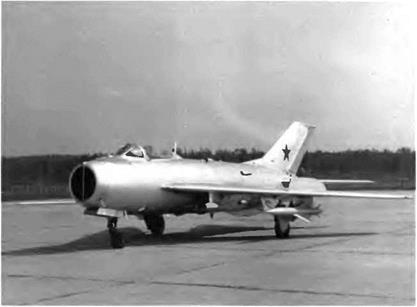
The SM-9/3 was the master aircraft for the mass-produced MiG-19.

—both pitch and roll channels were equipped with irreversible servo-controls driven by their own hydraulic circuit, the utility hydraulic system being used as a backup system; switching over the utility system was automatic when hydraulic pressure dropped below 65 kg/cmz (925 psi)

—the pitch control system (actuating rods) was, as a master control, equipped as well with an irreversible servo-control, the utility hydraulic system being also used as a standby system —the slab tailplane had both third – and fourth-level emergency con­trols (an electromechanism actuated by the control column itself and a set switch on the column, respectively), the electromech­anism cut in automatically when hydraulic pressure dropped below 50 kg/cm2 (710 psi)

—the gear ratio between the control column and the slab tailplane changed according to the dynamic pressure and flight altitude— that is, according to the Mach number—thanks to the ARU-2A automatic feel control unit. The control column forces on the lon­gitudinal axis were controlled by a Q-spring assembly in the ARU – 2A mechanism. The aerodynamic hinge moment of the slab tailplane was not fed back to the column. This device allowed the pilot to master the aircraft’s handling characteristics without hav­ing to think about the dynamic pressure or the Mach number. It was designed, tested, and built by a highly talented engineer and a historian of aviation, A. V. Minayev, who broke new ground in the field of flying control systems and was later appointed chief con­structor and denutv minister of aircraft Droduction.

image203

—a 0.54-m2 (5.8-square foot) ventral fin was added to improve direc­tional stability

—both prototypes were equipped with three airbrakes, two flanking the rear fuselage and one under the middle part of the fuselage

The armament of the SM-9/2 consisted of three NR-23 cannons (two in the wing roots and one on the right side of the lower forward fuselage). It could also carry two or four rocket pods for 57-mm ARS-57 rockets. The main on-board systems included the RSIU-4 Dub (“oak") VHF, the SRO IFF transponder, a radar warning receiver, the SRD-3

image204

The MiG-19S had a slab tailplane and a third airbrake under the fuselage developed on the SM-9/3.

Grad (‘’hail”) or SRD-1M Konus (“cone") ranging radar linked to the AS P-5 M gunsight, and the OSP-48 ILS. The SM-9/2 was moved to the flight test center in September 1954 and was taken up by G. A. Sedov on 16 September.

As of 4 May 1955 the OKB and GK Nil VYS pilots had made fifty – eight flights and noted the outstanding qualities of the SM-9/2, espe­cially its climb rate of 180 meters per second (35,400 feet per minute) at sea level. The appraisal of OKB pilots Sedov, Mosolov, Kokkinaki, and Nefyedov and Nil WS pilots Blagoveshchenskiy, Antipov, Ivanov, Molotkov, Beregovoy, and Korovin was very positive. The state trials proved that both prototypes were sufficiently long-legged for fighters with a range of 1,300 km (810 miles), and that the sound barrier was no longer a barrier at all. Because of the ARU-2, the slab tailplane, and many other technological advances, the shortcomings of the SM-2 were just a bad memory now.

The aircraft was continuously updated during the tests. For exam­ple, its balance range at takeoffs and landings was increased by short­ening the displacement of the control column. Mosolov reached Mach 1.462 in the SM-9/2 by starting a dive at 9,300 m (30,500 feet). The SM – 9/3 was rolled out on 26 August 1955 and went up for its first flight on 27 November with Kokkinaki at the controls.

The SM-9/3 differed slightly from the SM-9/2. The three NR-23 cannons of the latter were replaced by three NR-30s. A one-second salvo weighed 18 kg (40 pounds) as opposed to 9 kg (20 pounds) in the

SM-9/2. The SM-9/3 also reached Mach 1.46 and became the master aircraft for the MiG-19, which was mass-produced in two factories.

Specifications

Span, 9 m (29 ft 6.3 in); length (except nose probe), 12.54 m (41 ft 1.7 in); overall length, 14.64 m (48 ft 0.4 in); fuselage length, 10.353 m (33 ft 11.6 in); height with depressed shock struts, 3.885 m (12 ft 8.9 in); wheel track, 4.156 m (13 ft 7.6 in); wheel base, 4.398 m (14 ft 5.2 in); wing area, 25 m2 (269 sq ft); takeoff weight, 7,560 kg (16,660 lb); max takeoff weight with two 760-1 (201-US gal) drop tanks and two rocket pods, 8,832 kg (19,466 lb); fuel, 1,800 kg (3,970 lb); wing loading, 302.4-353.3 kg/m2 (62-72.4 lb/sq ft).

Performance

Max speed, 1,452 km/h at 10,000 m (784 kt at 32,800 ft); with two 760-1 (201-US gal) drop tanks, 1,150 km/h (620 kt); max operating limit Mach number, 1.44; climb to 5,000 m (16,400 ft) in 0.4 min; to 10,000 m (32,800 ft) in 1.1 min; to 15,000 m (49,200 ft) in 2.6 min; range, 1,390 km at 14,000 m (860 mi at 45,900 ft); with two 760-1 (201-US gal) drop tanks, 2,200 km (1,365 mi); service ceiling, 17,500 m (57,400 ft); dynamic ceiling, 20,000 m (65,600 ft); takeoff roll with reheat, 515 m (1,690 ft); with dry thrust, 650 m (2,130 ft); with dry thrust and two 760-1 (201-US gal) drop tanks, 900 m (2,950 ft); landing roll with main gear braking, 1,090 m (3,575 ft); with all-wheel braking, 890 m (2,920 ft); with all-wheel braking and tail chute, 610 m (2,000 ft).

I-7U and 1-75 Series

1-711

The I-7U interceptor equipped with the Uragan-1 was developed once it became apparent that the I-3U would be grounded for lack of the right engine. The preliminary plans were completed in August 1956. The structure of the new aircraft was entirely reworked so that it could be powered by the Lyulka AL-7F turbojet, which delivered a dry thrust of 6,155 daN (6,240 kg st) and a reheated thrust of 9,035 daN (9,220 kg st). Except for a few standardized parts, the only piece of equipment common to both the I-3U and the I-7U was the Uragan-1 system Everything else was completely modified.

All of the main airframe assemblies were redesigned after recon­sideration of their basic principles. The fuselage diameter was increased, the wing sweepback С/4 was reduced to 55 degrees, and the gear kinematics were modified (the main gear retracted into the fuse­lage, their legs folding up inside the wing between the integral fuel tanks and the Fowler-type flaps). Many stamped panels were required for the wing and the tail unit The ailerons and other movable surfaces contained no ribs but rather a solid core. Armament comprised two NR-30 cannons located on either side of the fuselage alongside the wing root ribs and four optional automatic rocket pods under the wing with a total of sixty-four ARS-57M rockets.

The aircraft was moved to the test center on 26 January 1957 and on 17 April performed its first taxiing tests, during which the aircraft was lifted a few feet. The I-7U made its first flight on 22 April with G. K. Mosolov at the controls. On the thirteenth flight the landing gear on the right side collapsed as the aircraft landed, damaging the right wing. The aircraft was returned to the workshop for repairs and later made six more flights, the last one on 24 January 1958. On 12 February tests were canceled by the general designer. The aircraft was once more returned to the workshop; fitted with the AL-7F-1 engine, it became the 1-75F.

The tests had demonstrated the aircraft’s quick acceleration as well as its outstanding climb rate on either dry or reheated thrust, a distinc­tive feature of the 1-7U. On the other hand, the deflection travel of the stabilator proved to be sufficient at landing. When the aircraft reached Mach 1.6-1.65 it had a tendency to bank to the left, but its yaw stability remained satisfactory.

The resemblance between the 1-7U and the I-3U was quite superficial. The I-7U was in feet an entirely new machine.

The weapons system was the only common feature of the I-7U and I-3U The cone housing the Almaz ranging radar is centered on the I-7U.

256

Specifications

Span, 9.976 m (32 ft 8.7 in); overall length, 16.925 m (55 ft 6.3 in); fuse­lage length (except cone), 15.692 m (51 ft 5.8 in); wheel track, 3.242 m (10 ft 7.6 in); wheel base, 5.965 m (19 ft 6.9 in); wing area, 31.9 mz (343.4 sq ft); empty weight, 7,952 kg (17,525 lb); takeoff weight, 10,200 kg (22,480 lb); max takeoff weight, 11,540 kg (25,435 lb); fuel, 2,000 kg (4,410 lb); wing loading, 319.7-361.7 kg/m2 (65.5-74.1 lb/sq ft); max operating limit load factor, 9.

Performance

Recorded max speed with engine dry rating, 1,420 km/h (767 kt) (not recorded with reheated thrust because the Pitot-static probe readings were not corrected at high speeds; the max speeds that follow are design specifications); max speed with reheated thrust, 1,660 km/h at

5.0 m (896 kt at 16,400 ft); 2,200 km/h at 10,000 m (1,188 kt at 32,800 ft); 2,300 km/h at 11,000 m (1,242 kt at 36,080 ft); climb to

5.0 m (16,400 ft) in 0.6 min; to 10,000 m (32,800 ft) in 1.18 min; ser­vice ceiling, 19,100 m (62,650 ft); landing speed, 280-300 km/h (150-162 kt); endurance, 1 h 47 min; range, 1,505 km (935 mi); takeoff roll, 570 m (1,870 ft); landing roll, 990 m (3,250 ft).