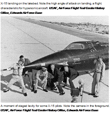
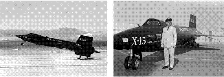
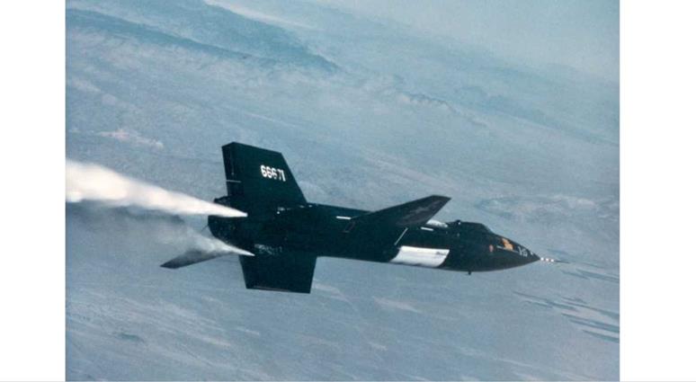
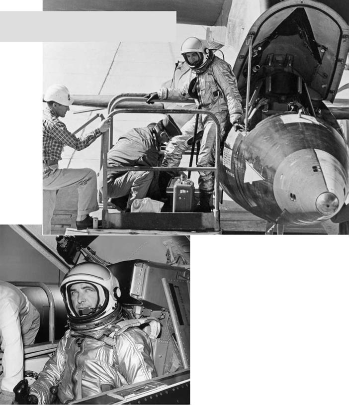
Category X-15 THE WORLD’S FASTEST ROCKET PLANE AND. THE PILOTS WHO USHERED IN THE SPACE AGE

THE BELL X-1

image38In 1939, Ezra Kotcher, an instructor at the U. S. Army Air Corps Engineering School (much later the Air Force Institute of Technology) at Wright Field near Dayton, Ohio, took up the banner for a high-speed research airplane. Like John Stack, Kotcher had come to the conclusion that viable technical data for the supersonic flight regime could be obtained only with a real airplane. In August 1939, after two years of analysis and study, Kotcher wrote a report describing his views on the problems that future aeronautical research and development would face. He concluded that a high-speed research airplane could be powered only by a gas turbine or a

X-15 just after being mounted to the wing of the B-52 mother ship. USAF, Air Force Flight Test Center History Office, Edwards Air Force Base


image39

image40

Me 262. USAF


rocket engine; a propeller-driven airplane would encounter insurmountable compressibility problems—shock waves on the blades—that simply could not be overcome. (To this day, no propeller-driven airplane has ever attained sustained supersonic speeds.) His report was reviewed by other engineers at Wright Field, and it eventually landed on the desk of Gen. Hap Arnold, who forwarded it to the NACA Langley Aeronautical Research Laboratory. There it met the same fate as John Stack’s memorandum. War clouds in Europe threatened, and the U. S. Army and the NACA had other pressing business.

By early 1944, the situation had changed completely. Germany was flying the twin-jet Me 262 jet fighter, against which Allied fighters and bombers were virtually helpless. The United States entered the jet age with the Bell P-59, a large, rather cumbersome jet with disappointing performance. Front-line propeller-driven fighters such as the North American P-51 and Republic P-47 flew faster. The Air Force had to face the
reality of flying into the transonic region, where there was no theoretical, wind tunnel, or flight data. Kotcher’s earlier proposal for a high-speed research airplane suddenly received priority attention. In January 1944, the Air Force issued “Confidential Technical Instruction 1568,” initiating a study for the development of an experimental airplane to probe the transonic flight regime. Starting with Kotcher’s original calculations, a small team of aeronautical engineers at Wright Field prepared a concept design of a rocket-powered airplane, soon to be labeled Mach 0.999. This design was vetted at a meeting of Air Force, Navy, and NACA engineers held at the Langley Aeronautical Laboratory in Hampton in mid-May 1944, where Kotcher reported the results of the Wright Field “Mach 0.999” study.

The final link in the development of a transonic research airplane took place in Ezra Kotcher’s office on November 30, 1944, when Robert Woods, Bell Aircraft’s chief of engineering, dropped by for a casual visit and expressed a

Подпись: Republic P-47. USAF image43
general interest in transonic developments. Kotcher seized the moment and shared the results of the “Mach 0.999” project, adding that the Air Force was having some difficulty finding an airplane company with enough time and interest to build such an airplane. Woods said that Bell Aircraft could do the job. The Bell X-1 was born.

The usual method for designing a new airplane is to first look at the previous one and then improve on it. The Bell designers had to start from scratch. Operating in a completely new design
space, Bell went to the Army’s Aberdeen Proving Ground in Maryland to study the aerodynamics of.50-caliber machine gun bullets, which were known to be slightly supersonic. The shape was stable, and the scatter of the bullets was minimal. The shape of the Bell X-1 fuselage is that of a.50-caliber machine gun bullet.

The concept of swept wings for high-speed airplanes originated with German engineer Adolf Busemann in 1935, and extensive wind tunnel research on the aerodynamics of swept wings advanced under German engineers under the shroud of secrecy of World War II. These swept – wing data were uncovered by the surprised Allied scientists who went into the German laboratories in May 1945. The data and its significance, however, were too late to be of direct use to the Bell designers. The Bell X-1 had straight wings.

From pioneering studies of the aerodynamic flow over airfoils at high subsonic speeds by the NACA in the 1930s, it was well known that thin airfoils delayed the formation of shock waves over

Подпись: Bell X-1 at Smithsonian. Note the similarity between the shape of the M2 bullet and the nose. NASM
the airfoils to higher speeds, thus delaying the adverse compressibility effects of shock-induced flow separation, with the consequent large increase in drag, dramatic loss of lift, and almost instant change in stability characteristics. The wing of the Bell X-1, therefore, had a relatively thin airfoil. The precise airfoil thickness was, however, a compromise. Two wings for the X-1 were designed and utilized: an 8-percent thick wing using an NACA 65-108 laminar flow airfoil, and a 10-percent thick wing using an NACA 65-110 laminar flow airfoil.

The thinner wing was used for flights in which maximum speed was the object. The thicker wing, which would encounter compressibility effects at slower speeds, was used for detailed aerodynamic
research investigations of the physical nature of transonic flow over the wing. In this fashion, the Army could pursue the quest for supersonic speed using the thin wing, and the NACA could pursue its quest for obtaining detailed flight data using the thick wing. Because the Army was paying for the X-1, the early part of the X-1 flight program was focused on obtaining supersonic flight as a goal in itself.

The design of the X-1 set the mold for many of the research aircraft that followed. It was rocket – powered. The engine was especially designed for the X-1 by Reaction Motors and was labeled the XLR11, with a maximum of 6,000 pounds of thrust obtained from a total of four separate chambers. The thrust could be modulated by firing

image45

Bell X-1 in flight. NASA Dryden Flight Research Center

Bell X-5 showing swept wings, composite photo. NASA

any one or more of the chambers. The X-1 was air- launched from a B-29 bomber; the alternative of taking off from the ground would have consumed too much fuel and not allowed the airplane to reach transonic speeds. Some researchers in the NACA, John Stack included, argued that the research airplane should be powered by a turbojet, thus allowing ground takeoff. Ezra Kotcher and the Army strongly argued against this scenario, and as mentioned earlier, the Army was putting up the money.

Three X-1 aircraft were manufactured by Bell. The first rolled out the Bell factory door on December 27, 1945, without its rocket engine.

The unpowered X-1 was transported to the Air Force’s Pinecastle Field near Orlando, Florida, for a series of glide tests to examine stability and control characteristics, and to examine low – speed behavior. Carried aloft by a B-29 bomber, the X-1 successfully completed ten glide flights.

In each, the airplane behaved beautifully at low speeds. This airplane was then transported back to Bell’s factory in Niagara Falls, New York, for installation of its rocket engine. The center of activity now shifted to the Muroc Army Air Field in California, where the powered flights were to take place. There, Bell test pilot Chalmers H. “Slick” Goodlin continued flying the X-1, as called for in the contract. The second X-1 was delivered to Muroc on October 7, 1946, followed shortly thereafter by the first X-1. By May 27, 1947, Bell had completed all the contractually required test flights (all subsonic), and the airplanes were turned over to the Army Air Force.

The Army selected Capt. Charles (Chuck) Yeager to be the next test pilot for the X-1. The Army’s first flight, with Yeager at the controls, took place on August 6, when the X-1 was carried aloft by the B-29 carrier aircraft above Muroc for a pilot-familiarization flight. It was the thirty – eighth time that any of the X-1s had taken to the
air. Over the next two months the flight-testing program called for a slow increase in speed, gradually approaching the speed of sound. On October 8, Yeager squeezed the airplane to a Mach number of 0.925; two days later, he flew at Mach 0.997. The fiftieth flight took place on October 14,

1947. Although the flight plan did not officially call for it, Yeager brazenly pushed the X-1 through Mach 1, to Mach 1.06. On that day, aviation history was made. It was the first supersonic flight of a piloted airplane, perhaps the most important event in aviation history since the Wright brothers’ first successful flight at Kitty Hawk on December 17, 1903. Moreover, the flight was smooth with no technical problems. The existing myth of a “sound barrier” had been broken.

The Bell X-1 lived up to its role as the first airplane designed purely for the acquisition of research data. In total, there were 151 flights,

35 of which were supersonic. The highest Mach number reached by the X-1 was 1.45 on March 26,

1948, with Yeager at the controls. The X-1 was the progenitor of the X-15 in several respects. Both airplanes were rocket-powered. The X-1 proved the viability of a rocket engine for achieving high­speed flight at a time when no other powerplant was available to accomplish the mission. Both were air-launched for the same reason, namely

to conserve fuel to enable enough power for a long enough duration to achieve the design Mach number. Ezra Kotcher had argued forcefully for an air launch as opposed to taking off from the ground; he was proven right. This approach carried through to the X-15. The last flight of the X-1 took place on July 31, 1951, piloted by Scott Crossfield, who was also the first pilot to fly the X-15.

Differences in the interests of the three parties involved in the X-1 program were contentious at times. The NACA wanted slow, continuous testing below Mach 1 to fully and safely analyze transonic flow; the Army Air Force wanted to

image46

▲ X-1A in the belly of a B-29 bomber. USAF

▼ X-15 and X-1B. USAF, Air Force Flight Test Center History Office, Edwards Air Force Base


image47image48

image49reach supersonic capability quickly, to develop and build a fighter that would be faster than any enemy; Bell Aircraft wanted to meet its contract requirements and get paid, but also to reach the supersonic flight regime in a timely fashion and thus gain advantage in future procurements. The objectives of all parties were achieved. The NACA did its significant transonic testing and analysis, the Army Air Force had its supersonic airplane, and Bell Aircraft was rewarded for the design, building, and flight testing of the airplane.

MILTON O. THOMPSON

1926-1993

Milt Thompson holds the distinction of being the only X-15 pilot to have written a book on the X-15 program. Entitled At the Edge of Space: The X-15 Flight Program, it was published by Smithsonian Institution Press in 1992, a year before Thompson’s death. It is a highly recommended read for anybody interested in the inside story of the X-15 flight program. As the ninth test pilot to join the X-15 program, Thompson flew the airplane fourteen times, beginning on October 29, 1963. On November 27, 1963, the inertials failed at launch. On January 16, 1964, he reached Mach 4.92, but the speed brakes were extremely hard to open during the high aerodynamic heating phase. On February 19, at Mach 5.29, he had a premature burnout due to a clogged liquid oxygen line. His highest Mach number was 5.48, reached on January 13, 1965, during which he lost the pitch-and-roll damping mechanism during the pull-up/roll maneuver after burnout and temporarily lost control. His last flight in the X-15 was on August 25, 1965, when he achieved his highest altitude of 214,100 feet. The technical difficulties encountered by Thompson were typical of those encountered by all of the X-15 test pilots; there were very few totally “good flights” during the 199 flights of the airplane.

Milt Thompson was born on May 4, 1926, in Crookston, Minnesota. He became a naval aviator

Подпись:

Подпись: LIFTING BODIES

at age nineteen and served in China and Japan during World War II. After six years of active duty, he left the Navy and entered the University of Washington, where he graduated with a bachelor’s degree in aeronautical engineering in 1953. Following graduation, like many Washington graduates, he joined the Boeing Aircraft Company as a structural-test and flight-test engineer. He is one of only two X-15 pilots (along with Scott Crossfield) to have worked in the aircraft industry. One of the projects to which Boeing assigned him was testing the new B-52. In March 1956, he seized the opportunity to go to work for the

A lifting body is a wingless aerodynamic configuration that generates its lift from the body at high angle of attack, somewhat like the Space Shuttle. In the period between the X-15 and the Space Shuttle, several “lifting bodies” were designed and flown to explore principally the subsonic characteristics of this hypersonic aerodynamic shape in order to provide data for the subsonic portion of the Space Shuttle flight.

NACA’s High Speed Flight Station at Edwards Air Force Base as a research pilot.

At the time, the NACA had only five pilots, including future X-15 pilots Joe Walker, Jack McKay, and Neil Armstrong. Thompson worked on the early X-airplanes. Of this experience, he admitted that he “watched apprehensively as these programs wound down and were terminated.” He felt that the glory days of the X-airplanes were over and that he had missed it all. “In the next few years,” he later wrote, “I realized that I was wrong. The golden years were still to come.”

For Thompson, those glory years began when he was selected by the Air Force to be the only civilian pilot on the X-20 Dyna-Soar winged hypersonic vehicle project. Although he again witnessed yet another cancelation when the Dyna-Soar project was prematurely stopped, his participation on lifting entry bodies continued.

He was the first person to fly such a lifting body, the lightweight M2-F1. He continued to fly this

aircraft a total of forty-seven times, after which he made the first five flights in the all-metal M2-F2. He took all this experience to the X-15 program.

Thompson finished his active flying career in 1967. Two years later, he became chief of Research Projects, and in 1975 he was appointed chief engineer, a position he held until his death on August 6, 1993.

THE BELL X-1A

Exactly one month after Chuck Yeager had made history by breaking the sound barrier in the X-1, the Army Air Force began a new study with Bell

for an airplane to fly at Mach 2. Labeled the X-1A, the new airplane had the same wing and horizontal stabilizer and the same rocket engine as the X-1, but it had a completely new fuselage with a more slender shape (higher fineness ratio and increased propellant storage).

On December 12, 1953, Yeager flew the X-1A to a Mach number of 2.44 at 70,000 feet. This set an unofficial world speed record. During the flight, while at this Mach number and altitude, the airplane suddenly encountered inertial roll-coupling and went out of control. Yeager was knocked semi-conscious in the cockpit as the airplane wildly descended. Fortunately, at 25,000 feet, Yeager was able to regain control. Although not intended to be part of the research flight plan, this was the

Douglas D-558-2 Skyrocket. NASA


US. NAVY


image50

ф’нф’фї


image51

X-1A on the lakebed. NASA Dryden Flight Research Center

first time that such roll-coupling at supersonic speeds had been encountered, although it had been predicted earlier by some aerodynamicists. The Air Force subsequently limited the top speed of the X-1A to Mach 2. Yeager, however, was not the first pilot to fly at Mach 2 or higher. This honor went to Scott Crossfield, who flew the swept – wing Douglas D-558-2 Skyrocket to Mach 2 on November 20, 1953.

The last flight of the X-1A was a captive flight in the carrier B-29. On August 8, 1955, as the B-29 was ascending to launch altitude, the X-1A suffered an internal explosion. The pilot, Joe Walker, in an act of heroism, saved himself and the crew of the B-29, but the X-1A was jettisoned and fell to the desert floor. Joe Walker was the second man to fly the X-15.

WILLIAM J. KNIGHT

1929-2004

Подпись: Pete Knight kneeling beside the X-15. USAF, Air Force Flight Test Center History Office, Edwards Air Force Base Подпись: Knight standing beside the X-15 after a flight. USAF, Air Force Flight Test Center History Office, Edwards Air Force Base
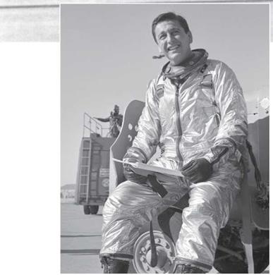
During the course of his sixteen flights in the X-15, William “Pete” Knight experienced perhaps the most notable event of all the pilots who flew the airplane. On October 3, 1967, he achieved Mach 6.7, the fastest speed attained in the X-15.

Подпись: Knight in the cockpit of the X-15 after a flight. USAF, Air Force Flight Test Center History Office, Edwards Air Force Base

By virtue of this flight, Pete Knight still holds today the world’s speed record in a winged, powered aircraft.

On this same flight, the X-15 was coated with a white ablative heat shield. Attached underneath the X-15 was a dummy model of NASA’s high-speed research engine (HRE), part of a research program to develop a supersonic combustion ramjet engine (scramjet). During the course of the test, the shock wave from the engine cowling impinged on the bottom surface of the X-15. The intense aerodynamic heating in the impingement region burned through the attachment pylon, separating the dummy scramjet from the airplane. Had the dummy engine remained attached any longer to the airplane, the shock wave would have burned a hole into the primary structure of the fuselage
and most likely would have resulted in destruction of the X-15 in flight. Moreover, this was the last flight of the X-15A-2. The airplane is now on permanent display in the Air Force Museum at Wright-Patterson Air Force Base in Ohio.

Pete Knight was born on November 18, 1929, in Noblesville, Indiana. At the age of twenty – one, he enlisted in the Air Force, and he obtained his pilot’s wings in 1953. He was assigned to the 438th Fighter-Interceptor Squadron, flying Northrop F-89 Scorpions. While flying the F-89, he entered the National Air Show at Dayton,

Ohio, in 1954 and won the prestigious Allison Jet Trophy, becoming one of the youngest pilots to win the award. He then began his engineering study program, and he graduated from the Air Force Institute of Technology in 1958 with a

Подпись:bachelor’s degree in aeronautical engineering.

With his career on a fast track, he graduated from the Air Force Test Pilot School that same year. Assigned to Edwards Air Force Base, he was a project test pilot for the F-100, F-101 Voodoo, F-104 Starfighter, T-38, and F-5.

The Air Force recognized Knight’s expert piloting ability by selecting him in 1960 to be one of the six test pilots for the X-20 Dyna-Soar, a winged orbital space vehicle that was an early precursor to the Space Shuttle. The X-20 program was canceled in 1963, but Knight went ahead to complete the Air Force astronaut training program at Edwards Air Force Base. With this background, Pete Knight became the tenth X-15 test pilot, and he had his first flight in the airplane on September 30, 1965. He flew the X-15 sixteen times. On October 17, 1967, he achieved an altitude of 280,500 feet, qualifying him for official astronaut status.

On June 29, 1967, Knight experienced total power failure while going through 107,000 feet at Mach 4.17. All onboard systems shut down.

He coasted to a maximum altitude of 173,000 feet and calmly set up a visual landing approach. He resorted to the old “seat-of-the-pants” flying and glided safely to an emergency landing at Mud Lake, Nevada. For this expert example of flying, he earned a Distinguished Flying Cross.

On July 16, 1968, Knight had a hydraulic gauge malfunction during boost, which required him to push over to an alternate flight profile, which is the planned variation of speed, altitude, and location for the flight of the aircraft. On his glide back to Edwards, he experienced unexpected shaking and vibrations. His last flight in the X-15 was on September 13, 1968; this was the 198th flight of X-15, the next to last flight of the program.

Pete Knight went on to a stellar Air Force career. He went to Southeast Asia in 1969 and completed a total of 253 combat flights in the F-100. His testing career was then extended to the F-15 program at Wright-Patterson Air Force Base as test director; he became the tenth pilot to fly the F-15 Eagle. He then returned to Edwards in 1979 as vice commander of the Air Force Flight Test Center. After thirty-two years of service and more than 6,000 hours in the cockpits of more than a hundred different aircraft, he retired from the Air Force as a colonel in 1982.

Knight became the only X-15 pilot to go into politics. In 1984, he was elected to the city council of Palmdale, California, and he became the city’s first elected mayor four years later. After becoming the fastest airplane pilot in the world, he thus became mayor of the fastest growing city in the United States. He was elected to the California State Assembly in 1992 and to the California State Senate in 1996. Knight achieved widespread public notice as the author of Proposition 22, the purpose of which was to ban same-sex marriage. He continued to serve in the California State Senate, representing the 17th District, until his death on May 7, 2004.

THE BELL X-2

As far back as 1935, German aerodynamicist Dr. Adolf Busemann gave a paper at the fifth Volta Conference in Rome in which he introduced the swept wing as an idea for reducing the drag of supersonic airplanes. The conference topic, “High Velocities in Aviation,” was forward­looking. At that time, the speeds of typical aircraft were in the range of 250 miles per hour, and supersonic aircraft were not yet on the radar. Busemann’s swept-wing idea was virtually ignored by the audience, an “invitation only” crowd that consisted of some of the most important aerodynamicists of the day. Ignored, that is, by everybody except the German Luftwaffe, which classified the concept in 1936—one year after the Volta Conference. During World War II,

image52

X-15 mounted under the wing of the B-52 for its first captive flight. USAF, Air Force Flight Test Center Flistory Office, Edwards Air Force Base

the Germans carried out secret, extensive aerodynamic research on swept wings, producing volumes of wind tunnel data, which was subsequently discovered by the Allied intelligence teams that went into German laboratories at the end of the war. Moreover, in 1944, R. T. Jones, one of the NACA’s best aerodynamicists, had independently proved the viability of the swept wing for reducing wave drag on high-speed wings.

This new information on swept wings, nevertheless, was too late for practical use by the designers of the X-1, who had already gone too far in the straight-wing design for the X-1.

But to compensate, the Air Force and Bell signed a new contract on December 14, 1945, for the design, development, and construction of an entirely new swept-wing X-aircraft, the X-2. This research aircraft was designed for speeds above Mach 3, which put it in the flight regime where aerodynamic heating becomes an important consideration. In fact, the investigation of aerodynamic heating at high Mach numbers was one of the principal drivers for the X-2. The skin temperature varies approximately as the square of the Mach number. Everything else being equal, the skin temperature of the X-2 (Mach 3) is nine times higher than that for the X-1 (Mach 1). This required that the X-2 be fabricated from K-monel and stainless steel alloys, rather than aluminum. Also, supersonic aerodynamics of the day dictated that an optimum supersonic airfoil shape be a thin bi-convex (circular arc) with an extremely sharp leading edge. The 40-degree swept wing of the X-2 had a thin, circular arc airfoil and an aspect ratio of 4.

Like its predecessors, the X-2 was rocket – powered. The X-2 contract included the engine, and Bell had designed for 15,000 pounds of thrust provided by two rockets, one with 5,000 pounds of thrust mounted above the other, which had 10,000 pounds of thrust. Each engine was oriented so that the thrust vector of each went through the center of gravity of the airplane. Each engine was throttleable to half, so there would be continuous thrust levels from 2,500 pounds to 15,000 pounds. The Air Force selected Curtiss-Wright, which— with Bell’s approval—took over the development of the rocket motors.

Bell Aircraft was responsible for the installation and testing of the rocket engine and for its operation during flight. Bill Smith, Bell’s chief of rocket engines, personally led these test efforts at Edwards Air Force Base, and he monitored the live static rocket testing on the ground from about 25 yards away from the airplane. (This was a far cry from modern rocket engine testing, which is conducted from concrete block houses to protect the test operators.)

Подпись: r v - V

image53

Подпись: CURTISS-WRIGHT

X-2 with its B-50 mother ship, support vehicles, support personnel, support helicopter, and chase planes. NASA Dryden Flight Research Center

The Air Force wanted to involve another company in the aircraft rocket engine business in addition to Reaction Motors, and with the agreement of

image54

Bell, they chose Curtiss-Wright. The Curtiss – Wright Corporation was formed in 1929 from the consolidation of the Wright Aeronautical and Glenn Curtiss companies, combining the two most important aeronautical pioneers in the history of early flight in the United States. Curtiss – Wright produced the famous P-40 during World War II, the airplane that was flown by the Flying Tigers in China. After the war, Curtiss-Wright fell behind in the design of jet airplanes and phased out of the aircraft design field, taking up the production of aircraft components and simulators.

Their excursion into aircraft rocket engines, prompted by the X-2, was transitory.

The decision to go with Curtiss-Wright for the engines ultimately resulted in delays. Although Bell produced two airframes by early 1953, only one engine was available, and that not until early 1953. Ironically, one X-2 was lost due to an engine explosion that took place in the bomb bay of the B-50 carrier aircraft. On May 12, 1953, company test pilot Jean Ziegler participated in a captive test flight that was intended to qualify the liquid oxygen top-off and jettisoning system. (A captive test flight is a flight in which the airplane is carried aloft by the mother plane but never released. The X-2 remained attached to the B-50 for the entire
flight—thus the name “captive” test flight.) When the B-50 was at 30,000 feet over the center of Lake Ontario, an explosion took place. The B-50 was tossed 650 feet upward, and the X-2 disintegrated. Both Ziegler and B-50 observer Frank Wolko were lost. The B-50 immediately returned to its home base. The weather was bad, with a heavy overcast ceiling of about 10 feet. It remained bad for a week, and searches to find the two men by Bell and government aircraft found nothing.

Test flying of the X-2 continued with the second aircraft. From August 8, 1954, to September 27, 1956, a total of seventeen flights were made in

the second X-2. On July 23, 1956, with Air Force Capt. Frank Everest at the controls, the X-2 set a new unofficial world speed record of Mach 2.87. Two months later, on September 27, 1956, the X-2 made aviation history, becoming the first airplane to fly faster than Mach 3. With Air Force Capt. Milburn Apt at the controls, the X-2 set an unofficial world speed record of Mach 3.196. This was Apt’s first flight in the X-2; he flew a near-perfect flight plan to a maximum altitude of 72,000 feet and nosed over, attaining the maximum Mach number at 66,000 feet. However, Apt then put the X-2 in a slight roll, not in the flight plan. The X-2, due to inertia coupling, was unstable in roll at that Mach number and went out of control. The airplane and pilot were both lost, underscoring the dangers of test flying in unknown flight regimes.

WILLIAM HARVEY “BILL” DANA

1930-

Bill Dana was the eleventh X-15 test pilot. He flew the X-15 sixteen times and was the pilot for the 199th flight, the last of the X-15 program.

Bill Dana was born in Pasadena, California, on November 3, 1930. He attended the United States Military Academy at West Point, graduating with a bachelor of science degree in 1952. He satisfied his military commitment by serving as a pilot in the U. S. Air Force for four years, after which he attended the University of Southern California. At USC, he graduated with a master of science degree in aeronautical engineering in 1958. He began his distinguished civilian career at the Dryden Flight Research Center on October 1, 1958.

This was the first day that NASA went into operation, and Dana proudly became NASA’s first employee. He was involved with the X-15 from that first day, initially as an engineer, then as a chase pilot, and finally as a project pilot. His first X-15 flight was on November 4, 1965, a checkout flight during which he reached Mach 4.22 and an altitude of 80,200 feet. At this point in the X-15 program, even the pilot checkout flights were relatively high – performance. This flight required two relights of the rocket engine. On October 4, 1967, Dana reached his highest speed, Mach 5.53, and on November 1, 1966, he achieved his highest altitude of 306,900 feet, one of two flights he made above 50 miles.

By the end of the X-15 program, Dana was just at the beginning of his distinguished career as a test pilot and aeronautical engineer. Building on his experience flying the X-15, he became a project pilot for NASA’s manned lifting body program, a precursor to the Space Shuttle. He completed one NASA M2-F1, nine Northrop HL-10, nineteen Northrop M2-F3, and two Martin Marietta X-24B flights, for a total of thirty-one lifting body missions. For this work, he received the NASA Exceptional Service Medal.

In 1976, Dana received the Haley Space Flight Award from the American Institute of Aeronautics and Astronautics. In 1986, he became the chief pilot at the Flight Research Center, and he then became the assistant chief of the Flight Operations Directorate. He continued to fly on several important research programs: the F-15 Highly Integrated Digital Electronic Control and the F-18 High Angle of Attack program. In August 1993, Dana became chief engineer of the NASA Dryden Flight Research Center, and he held that position until his retirement in 1998.

After retirement, Dana began a distinguished second career by working as a contractor with the NASA Dryden History Office. He was honored by the Smithsonian’s National Air and Space Museum in 1998 when he was selected to give the Charles A. Lindbergh Memorial Lecture, the most prestigious lecture at the museum. His lecture title was “A History of the X-15.” He still continues to lecture and write papers based on his experience in high-speed flight.

RELEVANCE TO THE X-15

The X-1, X-1A, and X-2 were precursors to the X-15 and were relevant to the future design of X-15, for the following reasons:

1) They were designed to be strictly research airplanes.

2) They were all powered by liquid-fuel rocket engines.

3) They were all air-launched. They were designed with no intention of ever evolving into viable military combat aircraft.

These research aircraft accomplished the first three steppingstones to high-speed flight: the X-1 to Mach 1, the X-1A to Mach 2.44, and the X-2 to Mach 3.2. The next phase was going to be huge, stepping into the regime of hypersonic flight. This was to be the role of the X-15.

image57

▲ B-52 mother ship taking off with the X-15 mated under its wing. USAF,

Air Force Flight Test Center History Office, Edwards Air Force Base

▼ X-15 landing with an F-104 chase plane following close by. USAF, Air Force Flight Test Center History Office, Edwards Air Force Base

43


image58

image59

X-15A-2 under the wing of the B-52 mother ship in flight. USAF,

Air Force Flight Test Center History Office, Edwards Air Force Base


image60

MICHAEL J. ADAMS

1930-1967

Mike Adams was the twelfth (and last) pilot in the program, and he was the only pilot to lose his life flying the X-15.

On November 15, 1967, Michael Adams, veteran pilot with six previous X-15 flights, entered the aircraft for a flight to evaluate a guidance display and to conduct several experiments. He had spent more than 21 hours practicing the specifics of this flight in the simulator. The drop at about 10 a. m. and 45,000 feet was normal, and he climbed to 266,000 feet. While the aircraft climbed to higher altitude after launch, an electrical disturbance caused the MH – 96 dampers to trip out. Adams reset the dampers. He then switched the sideslip indicator to a vernier

Подпись: Mike Adams in the X-15 cockpit before his first flight, October 6, 1966. USAF, Air Force Flight Test Center History Office, Edwards Air Force Base
attitude control mode to more accurately control the experiments. He planned to reset this back to indicate yaw angle when returning to base in order to see his sideslip during approach to landing. But this instrument change prevented him from seeing that the airplane was yawing at a critical time in the flight.

After burnout, as he soared upward, he conducted a wing-rocking experiment, in which the rocking became excessive as he approached his peak altitude, 266,000 feet. His yaw had drifted to 15 degrees, and he was unaware of this because his instrument was inadvertently set to show pitch attitude, not yaw. About 15 seconds later, the airplane was yawing wildly and Adams
communicated to Pete Knight that “the airplane seems squirrelly.” He soon after stated that he was in a spin, subjected to high accelerations. Since little was known about the hypersonic spin characteristics of the airplane, the ground crew was not able to offer advice. According to the ground data that was later correlated with the flight data, when Adams recovered, he was yawed 90 degrees, flying upside down, and descending at supersonic speed.

Adams pulled out of the spin, and he probably would have had a successful landing except that the MH-96, the Minneapolis-Honeywell adaptive flight control system, was on and locked in, causing the airplane to oscillate between its limits,

Подпись: Adams suited up and walking to the X-15 for his first flight. USAF, Air Force Flight Test Center History Office, Edwards Air Force Base
up and down, preventing Adams from correcting his attitude and flying his way home. The loads on the airplane built up beyond the structural limits, and the X-15-3 aircraft broke up at approximately 62,000 feet and about 3,800 feet-per-second speed. It crashed to the desert floor near Johannesburg, California. There was talk about Adams having slight vertigo, which may have contributed to his not noticing the yaw buildup or resetting the yaw indicator to the yaw setting.

Adams’s death shows the dangers of flight testing a new aircraft in previously untested regions of flight, and of flying experiments in which certain research-data measuring instruments may have caused an electrical

disturbance that affected the MH-96 from operating at its top quality and in conditions it was not designed for. Any and all these things may have influenced the accident.

Because his flight was above 50 miles high, Adams was posthumously awarded an astronaut rating. For the X-15 program, the tragedy was a blight, but it was the only casualty in 199 flights. Since the objectives for the airplane had been accomplished, the accident was a major reason for the termination of the X-15 program. There were only seven subsequent flights.

Michael Adams was born on May 5, 1930, in Sacramento, California. After graduating from Sacramento Junior College, he enlisted in the Air

Подпись: ROTATIONAL MOTION

The rotational motion of an airplane in flight takes place centered around the airplane’s center of gravity. It is a combination of three rotational directions: the nose up or down rotation, called pitch; the wing rotation about the fuselage, called roll; and the nose swinging right or left, called yaw.

Force in November 1950. The Korean War was in full force at that time, and Adams flew forty – nine combat missions as a fighter-bomber pilot in Korea. In 1958, he earned an aeronautical engineering degree from the University of Oklahoma, and he went on to eighteen months of study at MIT in astronautics. In 1962, he was selected to attend the Experimental Test Pilot School at Edwards Air Force Base. He excelled at the school, winning the Honts Trophy as the best scholar and pilot in his class. In December 1963, he graduated with honors from the Aerospace Research Pilot School. His first flight in the X-15 was on October 6, 1966. On June 8, 2004, a memorial monument to Adams was erected near the crash site, northwest of Randsburg, California.

Test pilots are a special breed. They face risks above and beyond those faced by conventional pilots. The X-15 pilots, however, are in a special class. They were research test pilots, putting their lives on the line to prove the viability of a pioneering hypersonic airplane and to obtain research data on an unknown regime of flight.

This data was invaluable to the subsequent design of the Space Shuttle.

image148On almost every flight of the X-15, some type of technical problem or failure occurred, sometimes multiple problems on the same flight.

Signed photo of six of the X-15 pilots standing beside the X-15. From left to right: Rushworth, McKay, Peterson, Walker, Armstrong, and White. USAF, Air Force Flight Test Center History Office, Edwards Air Force Base


image149

X-15 mounted under the wing of the B-52 prior to a flight. USAF, Air Force Flight Test Center History Office, Edwards Air Force Base


image150

image151

image152X-15 on the lakebed of Rogers Dry Lake. USAF, Air Force Flight Test Center History Office, Edwards Air Force Base

It is remarkable that only one pilot, Mike Adams lost his life during the whole X-15 program of 199 flights. Ten of the twelve had formal college degrees in aeronautical engineering and took pride in their status as dedicated, professional aeronautical engineers. All served at one time or another in the military, and six (Crossfield, Walker, McKay, Armstrong, Thompson, and Dana) were in civilian status when they flew the X-15. Of the career military officers who flew the X-15, three retired as major generals in the Air Force and one as a vice admiral in the Navy.

B-52 flying over the X-15 on the ground. USAF, Air Force Flight Test Center Flistory Office, Edwards Air Force Base


image153image154

AIRPLANE AND ITS ENGINES

THE AIRPLANE

The X-15 was born on October 5, 1954, when the NACA Committee on Aerodynamics finally decided on the need for a manned hypersonic research airplane. No airplane had even come close to flight at Mach 5 or higher. The Bell X-1 had achieved Mach 1, the Bell X-1A Mach 2.44, and the Bell X-2 Mach 3.2. But to greenlight the development of an airplane that could fly at Mach 7 was truly visionary. No such manned airplane had ever been designed, much less built. Normally, engineers study the previous incarnation of the plane they want to build, innovating from these earlier successful design ideas. But the X-15 was revolutionary—no “before” design even existed. The team would have to start from scratch.

image61image62And for good reason.

image63

image64

X-15-3 on the lakebed. USAF, Air Force Flight Test Center History Office, Edwards Air Force Base


The X-15 airplane had to be able to accelerate to Mach 7 and climb to over 250,000 feet in order to fill in the unexplored range in speeds above Mach 3.2 and altitudes above 126,200 feet, the maximum achieved by the X-2. (The Bell X-1 had reached 71,902 feet, and the Bell X-1A had reached 90,440 feet.) Like its predecessors, the X-15 would be flown out of Edwards Air Force Base, which was the only installation that had the support equipment and personnel—it was the location of the Air Force Test Pilot School—to
handle the research test flights. Moreover, because of the high landing speed of the X-15, Edwards had the only “runway” long enough for landing the airplane—essentially the whole expanse of the Muroc Dry Lake bed.

The new airplane, like the X-1 and X-2 before it, would be rocket-powered with high thrust, and it would be carried aloft in a “mother ship” to save fuel by applying the thrust at an altitude where the air density was low (hence, low drag). The X-15 would also have to carry enough fuel

image65

▲ X-15 under the wing of the B-52 in flight. USAF, Air Force Flight Test Center History Office, Edwards Air Force Base

▼ X-15-1 mounted under the wing of the B-52 before its first flight, June 8, 1959, with Scott Crossfield in the cockpit. USAF, Air Force Flight Test Center History Office, Edwards Air Force Base

49


image66

Подпись: MONOCOQUE

Monocoque is a French word meaning “single shell.” Here, the fuselage is a single, hollow shell that carries on its surface the aerodynamic loads exerted on the fuselage. A monocoque fuselage allows maximum space inside the fuselage for internal components, such as fuel and oxidizer tanks, and electronic equipment. A semi – monocoque structure has additional elements inside the shell, such as formers that conform to the cross-sectional shape of the fuselage and stringers that run longitudinally along the fuselage. These provide additional structural strength while still preserving volume inside the fuselage for other components. These structural elements can be seen in the cutaway view of the X-15A-2 shown on the opposite page.

to allow the high thrust to operate long enough to accelerate to the speeds and altitudes needed to perform the mission. So, the airplane had to be big enough for the fuel volume needed and be able to carry a rocket engine with far more thrust than employed previously, as well as structural materials that would maintain strength at the high temperatures to which the airplane would be subjected at its high speeds of flight.

The design also had to consider the requirements of the nonhypersonic flight regimes for the other portions of flight: It would drop from the mother ship at high subsonic speed, accelerate through Mach 1 and the transonic speed region,
then through supersonic and hypersonic flight in getting to and from the targeted data points, and finally it would have to decelerate from hypersonic flight to return to the landing site, followed by descent and landing that had to occur at relatively low subsonic conditions.

Because of these specific design requirements, the engineers started with a blank slate, using all of the latest technologies that might apply to the new airplane and the extreme conditions, known and unknown, that it would endure. They also built upon their previous experience and knowledge of the known flight regimes to design an aircraft that could unveil the mysteries of hypersonic flight.

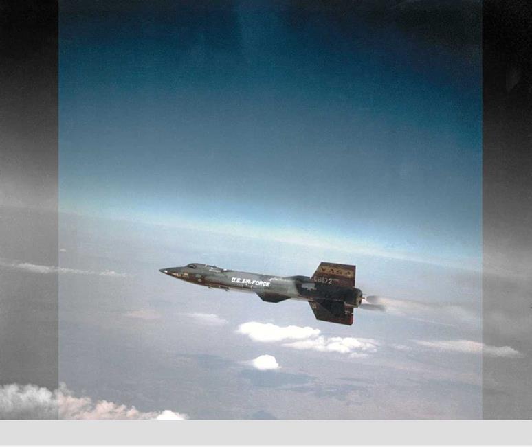
The X-15’s fuselage, wings, tail, size, and weight generally look conventional. The fuselage structure is monocoque and semimonocoque. The pilot compartment was a little more ample than that of a fighter jet. The wing has a span of 22 feet, uses an NACA 66005 symmetric laminar flow airfoil, has an area of 200 square feet and an aspect ratio of 2.5, and features a sweepback angle at the quarter chord of 25 degrees. The horizontal tail is tilted down from the fuselage, and the upper vertical tail looks like most others except that the airfoil is wedge-shaped with a blunt trailing edge, unlike the usual airfoil shapes.

But there are two major changes that further distinguish the X-15:

First, there are no ailerons on the wing; roll – control is achieved by deflecting differentially the right and left sections of the horizontal tail. Also, the horizontal tail has no elevators; instead, the whole right and left sections deflect in the same direction together to provide pitch control.

Second, the vertical tail has an unusual airfoil section. It is essentially a vertical slab, small and rounded at the leading edge and flat-sided at a 5-degree half-angle out to the trailing edge, which is blunt.

X-15 cutaway schematic. The Hypersonic Revolution, Vol. 1, edited by Richard P. Hallion, p. 141, USAF History Office


image67image68

X-15 three-side view.

NASA Dryden Flight Research Center

image69

Mach waves (very weak shock waves) on a

image70

Oblique shock waves on a wedge-type body, demonstrating that the stronger shock wave is at a larger angle than the weak Mach wave.

image71

Demonstration of the constant pressure exerted on the face of the wedge, downstream of the shock wave.

The leading edge is rounded in order to reduce the aerodynamic heating in that region. Overall, the vertical tail is a geometrically simple 10-degree total angle wedge with a blunt, flat surface for the trailing edge. The wedge shape has two aerodynamic advantages at supersonic and hypersonic speeds. First, the pressure on the flat sides is a constant downstream on the nose, and this encourages attached flow over the whole surface all the way to the blunt trailing edge. Expansion waves occur at each corner of the trailing edge. These expansion waves are the direct opposite of shock waves. The pressure decreases through an expansion wave, whereas it increases through a shock wave. The flow leaves the trailing edge through an expansion wave, and hence the pressure on the flat base of the vertical tail is lower. This in turn increases the aerodynamic drag on the vertical tail, called base drag, but at hypersonic speeds the base drag is a very small fraction of the overall drag.

The second aerodynamic advantage, and the primary reason for the use of the wedge shape, is increased directional stability. In August 1954, Charles H. McLellan, head of the 11-inch hypersonic wind tunnel at the NACA Langley Aeronautical Research Laboratory, published some stunning and almost counterintuitive results in NACA Research Memorandum LF44F21 entitled “A Method for Increasing the Effectiveness of Stabilizing Surfaces at High Supersonic Mach Numbers.” His work showed that the wedge shape “should prove many times more effective than the conventional thin shapes optimum for lower speed.”

The wedge shape took advantage of the nonlinear physics of shock waves as follows: If a surface in a supersonic flow is already inclined at an angle to the flow, say 5 degrees like the surface of a 5-degree half-angle wedge, and then the wedge itself is further inclined by an additional 2 degrees due to a control input, the pressure and hence the aerodynamic force on that surface (which is now at 7 degrees to the flow) is much higher than what would occur on a thin airfoil shape simply deflected by 2 degrees. Aerodynamicists at North American were aware of McLellan’s work, and they put this NACA

Подпись: X-15 hanging in the National Air and Space Museum. NASM
research to good use in the design of the X-15. The wedge-shaped vertical tail is clearly seen in the three-view of the X-15 (page 51). Of course, the wave drag on the tail was higher for this wedge airfoil; but the necessity for effective control authority was more important than this slight increase in drag due to the vertical tail, especially at high altitudes where the number of pounds of aerodynamic drag was small compared to the rocket engine’s high thrust of 57,000 pounds.

In spite of the wedge shape, wind tunnel tests showed that the vertical tail needed to be enlarged to have the necessary control authority. To accomplish this, a ventral tail was added below the fuselage. It was so large, however, that it would hit the ground in landing, in advance of the landing skids, which the X-15 used instead of wheels. To solve this problem, the ventral tail was split into two parts, and the lower section was made ejectable to solve the landing problem, with

image73

X-15 rear view detail. X-15 nose detail.

NASM NASM

Подпись: X-15 ventral tail. NASM
Подпись: X-15 reaction control jets detail. NASM

the drop made during approach to landing. This ejectable section was designed to be recovered and reused. However, later in flight testing, the engineers found that the lower ejectable half was not needed, and it was thus no longer used.

The pilot controls are conventional at low speeds, including launch and landing; power assist is provided on a separate control stick on the right console for use when the dynamic pressure is too great for the pilot force alone to move the control surface. But when the dynamic pressure is very low
and the control surfaces are not effective because the aerodynamic forces are too low, or these forces are nonexistent as when in space, small rocket motors with nozzles at the wing tips for roll, and at the nose and tail, help control pitch and yaw. The fuel for these motors is the monopropellant hydrogen peroxide. These rockets give the pilot control in outer space, where the aerodynamic force is zero, with the pilot using a separate control stick on the left console.

The structure is conventional, but the material affected by the external heating is Inconel X, which maintains its strength to above 2,000 degrees Fahrenheit. The support structure underneath is mostly titanium.

Speed brakes, located on the lower part of the upper vertical tail, were used for energy management to dissipate much of the energy generated by the rocket thrust in accelerating to high speed. It reduced the energy to be dissipated during the return trip to landing by increasing the drag, thus allowing a safe landing approach and touchdown. The landing gear consisted of a normal nose gear and twin metal skids instead of a conventional twin-wheeled gear, to save both weight and volume. During flight, the nose wheel

image76

Method by which the X-15 is mated to the B-52. USAF, Air Force Flight Test Center History Office, Edwards Air Force Base

55


image77

image78

was stored internally, and the skids were external, flush against the fuselage.

The nose of the X-15 was round (a ball nose), which reduced the aerodynamic heating to that site. It also indicated to the pilot the angle of attack and the yaw angle at which the plane was flying, because an instrument supplied by Nortronics and installed in the nose faced into the direction of flight, supplying this information to the pilot. The nose had a spherical shape, 12 inches in diameter, and was made of Inconel X, which also helped the airplane survive the extreme heat at its nose.

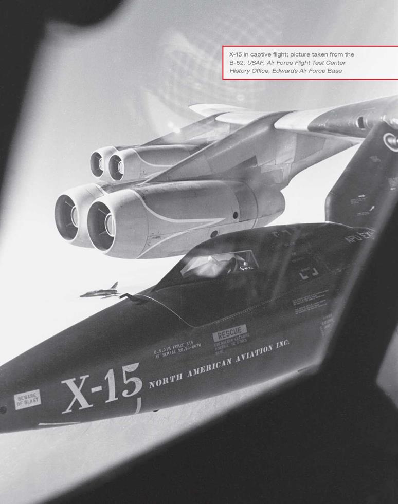
Because the X-15 was designed to be air – launched, it was mounted under the right wing of a B-52 mother plane, where it was carried aloft from the ground at takeoff until dropped by the B-52 after hitching a free ride to 45,000 feet and a Mach number of 0.85. Unlike the earlier X-airplanes, with which the pilot rode to altitude in the bomber mother ship and then climbed aboard after the X-airplane checkout was complete and the liquid oxygen (LOX) was topped off (replacing what had boiled off during the climb to altitude), the test pilot was in the X-15 cabin right from the start, even before takeoff. If trouble occurred during this climb to altitude, he would have no way out unless the B-52 used its controls to drop the entire X-15 aircraft.

Engineers modified the third airplane, the X-15-A2, to have two external fuel tanks and an extension of 29 inches in the fuselage for equipment and instrumentation. These external fuel tanks are shown in the X-15 cutaway on page 51.

A stability augmentation system, made by Westinghouse, dampened the aerodynamic controls in all three axes. Later, the Minneapolis – Honeywell MH-96 adaptive control system replaced the SAS. These systems were necessary because analyses of the aerodynamic data indicated that the airplane would be dynamically

image79

image80

X-15-3 with ablative coating mounted under the wing of the B-52 in flight. USAF, Air Force Flight Test Center History Office, Edwards Air Force Base

image81

X-15A-2, showing the external fuel tanks on the ramp of the NASA Flight Research Center at Edwards. USAF, Air Force Flight Test Center History Office, Edwards Air Force Base


Подпись: A detail showing the X-15 being mounted under the wing of the B-52. USAF, Air Force Flight Test Center History Office, Edwards Air Force Base

unstable without the system. The airplane was designed with reasonable cockpit visibility; the pilot could see all around, but he could not see the wings or the nose of the airplane.

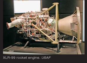
The fuel for the later X-15 flights using the XLR99 engine was anhydrous ammonia, and the oxidizer was liquid oxygen (LOX); the fuel for the earlier flights using the XLR11 engine was water-alcohol. Both fuel and oxidizer were carried in the fuselage and held by the outside structure of the fuselage. The fuselage also contained the hydrogen peroxide (H202), used for the small control rockets that operated at high altitudes. Nitrogen pressurized the cabin, and helium pressurized the fuel and oxidizer.

FLIGHTS

RISKS IN RESEARCH AIRCRAFT

When we talk about risk, we mostly mean the life of the pilot, the dangers to the man who governs the airplane through its flight path to the new conditions in flight that the new airplane will investigate. This is the life of a person who is talented, productive, and well experienced in test flying—and a human being unique in his flying abilities in high-speed and high-altitude flight.

Подпись: Bob White after a flight in the X-15. USAF, Air Force Flight Test Center History Office, Edwards Air Force BaseThese characteristics are in addition to all the other attributes that pertain to each person’s life. We also mean the risk to the airplane, which is important enough to have had many years of development, thousands of man-hours of workmanship, and millions of dollars in cost. If the airplane is lost, the research program for which it was designed is jeopardized.

image155

image156

image157

X-15 at the end of Jack McKay’s flight on May 6, 1966, during which the rocket engine failed after 35.4 seconds. The X-15 landed at Delamar and skidded off the smooth lakebed. McKay was not injured, and the X-15 sustained only slight damage. USAF, Air Force Flight Test Center History Office, Edwards Air Force Base


This research aircraft was designed to explore regions for flight at altitudes and speeds not yet then achieved. It incorporated a new, advanced design using new materials that allowed it to operate at higher temperatures than previously experienced. It had new and multiple control systems. It used a new rocket engine with a new fuel-oxidizer combination. It had twin skids rather than wheels for a landing gear.

Wind tunnel data existed for the aerodynamics in this new speed region, but it had not been evaluated and confirmed in flight. Moreover, not all the conditions of hypersonic flight that it experienced in the wind tunnel had been previously analyzed or fully understood. Some problems were not known until they were

discovered in flight. Therefore, they could not have been addressed in advance.

Before this aircraft could achieve hypersonic speeds and high altitudes, it still had to traverse all the flight regions previously explored. The new design had to prove that it could safely fly in those known flight regions. For example, it had to be able to take off on its own or be air-dropped in the subsonic regime. It then need to accelerate to high subsonic speeds, go through transonic flight, experience shock waves beginning at Mach 1, and accelerate to supersonic speeds, experiencing stability changes longitudinally, and thereafter in regions of reduced lateral-directional stability with increasing Mach number. It also had to decelerate and return to the landing site with normal

Подпись: Discussion before a flight. USAF, Air Force Flight Test Center Flistory Office, Edwards Air Force Base approach, descent, and landing, all without using thrusting power. It should be noted that although low-speed subsonic flight and landing had been analyzed for the X-15 for these conditions, they were not the primary focus of the design.

The pilots controlled many aspects of the flight, such as the handling and control actions about the three axes of the airplane and the application of thrust. But the pilots could not control other factors, such as the strength of materials at high temperatures and the effect of temperature gradients on the design and strength caused by high aerodynamic heating on the outside and cool internal temperatures.

The characteristics of the X-15 would not be definitively known and understood until verified or determined in actual flight. The handling characteristics in these regions were unique, controlled by the pilot with three different control systems: a traditional stick on the floor between the legs and a rudder; a small control stick on the right console, with power assist or electronic force amplification when experiencing dynamic pressures too high for normal pilot forces; and a rocket power control on the left console for use in space where the air is too thin and the dynamic pressure too low for aerodynamic control surfaces to be effective. In the X-15, the pilot experienced for the first time these new controls, designed for this airplane, following his drop from the B-52 at altitudes of about 40,000 feet and speeds of about Mach 0.8. There were no ground trials with the controls during taxiing or on short hops prior to a real test flight, as is possible while familiarizing oneself with the controls of a conventional aircraft that has wheels rather than skids and that has a jet or reciprocating engine instead of a rocket.

Pilots had to address new interfaces in each new test aircraft. For example, the X-15 was taken aloft by the B-52 and attached under the

B-52’s right wing, unlike the other rocket research aircraft. These previous X-airplanes were attached under the fuselage, allowing the test pilot to ride in the mother craft’s cabin and enter the test aircraft only after everything had been checked out. In the X-15, located out on the wing, the pilot had to enter his aircraft before B-52 takeoff, and he was at risk as the two airplanes climbed to altitude. He had to also check out the X-15 systems while riding in the X-15 after takeoff and prior to drop. He thus had to deal with the interface with the mother airplane mechanically and electronically, including communications, and also operationally by topping off the liquid oxygen and checking other conditions before separation and drop occurred in midair. In

Подпись: Crossfield in discussion after a flight. USAF, Air Force Flight Test Center History Office, Edwards Air Force Base image160
both the X-15 and B-52, the interfaces included the mechanical ties between subsystems and components, each of which had their own requirements, as well as continuity of electrical and electronic signals that signaled to and from the pilot’s cabin and the operating systems, as well as the thermal interfaces that controlled the heating and cooling needs of particular subsystems and components. Repairs could have adversely affected these initial design conditions. An example of this occurred when extra cooling was needed for a component after problems in flight and an extra cooling line was installed to fix the problem. This new cooling line ran alongside an APU hydraulic line that caused its hydraulic fluid to freeze, preventing the APU from functioning.

A conventional aircraft has a shakedown period in which the newly installed subsystems first operate together as a complete aircraft system. Then interfaces with other elements of the airplane are tested mechanically, electrically, and thermally in actual flight conditions when they can be fine- tuned. Experience has shown that many changes

Подпись: DAVID CLARK PRESSURE SUITor improvements are necessary in a new airplane. Routinely, there are bugs to work out, safety issues to resolve, and procedures to establish. For the flight-test program, there is a new support team from management through inspection. For an airliner, it may take two years of testing before it is put into use. There is no such luxury for these high-performance research aircraft. They start out in their very first flight at 40,000 feet in the air. Experience also has shown that unexpected difficulties are uncovered in air-launched research aircraft such as the X-1, X-1A, and X-2, in the increasing velocity regions of transonic and supersonic flight.

Such a flight program is necessarily risky.

This was a new airplane. The old flight regimes in which this plane had to traverse were not the prime focus in design. New equipment, previously untested in flight, was necessary, and the exploration was conducted in a new flight regime to ascertain the validity and shortcomings of the applicable theories, which were approximated with many simplifying assumptions and the use of wind tunnel test data.

Since the X-15 followed the course of the previous X-aircraft, it also had numerous difficulties with equipment—such as the auxiliary power units, landing gear, windshield and cockpit seals, stability in landing, and so forth—that required pilot experience, fortitude, and ingenuity to overcome. In the 199 flights, the problems were frequent, unanticipated, and in many instances life-threatening. It was the piloting excellence, the prior experience of the pilots and engineers, and the extensive preparation for each flight—including hours of simulation—that permitted these many flights to be completed with only one fatality.

Another difference from conventional aircraft testing relates to the lack of any power when the rocket fuel is expended. The fuel is used up in just about 90 seconds of flight. Conventionally

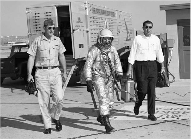
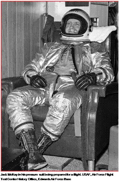
The David Clark full-pressure suit was developed by Dr. David Clark and produced in his small factory in Worcester, Massachusetts. Unlike previous partial-pressure suits that pressurized only parts of the human body, Clark’s full – pressure suit provided pressurization for the whole body. It was made from his patented Link-Net nylon fabric, which consisted of two layers of nylon arranged with opposite bias that provided maximum strength in high-stress areas while also allowing the suit to deform easily to the pilot’s movement. It was lightweight, but it held its shape under pressure. The suits were custom-made for each pilot, who had to make several trips to Worchester for fitting. Clark made improvements to the suit throughout the X-15 program. It became the standard full-pressure suit for the Air Force and NASA, being used by pilots of the U-2 and SR-71 high-altitude spy planes as well as the Space Shuttle astronauts. Several photographs in Chapter 5 show some X-15 pilots in their David Clark full-pressure suits.

powered aircraft can reposition themselves if in trouble or when in descent, approach to landing, and during the landing itself. All X-15 flight positions and corrections have to be done with aerodynamic controls alone, not with power. If the landing approach is too high or too low, the pilot must bring it down safely without power. He cannot go around the field a second time to try again. His first attempt must be successful.