Blumenthal Brings Unity
Otto Blumenthal had been Hilbert’s first doctoral student at Gottingen and continued to help Hilbert edit the distinguished journal Mathematische An – nalen.55 In the winter semester of 1911-12 Blumenthal, now at the TH in Aachen, gave a course of lectures on the hydrodynamic basis of flight. He described, mathematically, the irrotational flow of an ideal fluid over a range of different Joukowsky profiles. Along with his colleagues at Aachen, Karl Toep- fer and Erich Trefftz, he drew up diagrams of the precise shape of the profiles. The result of the joint work was published in two papers in the ZFM for 1913. The main paper, by Blumenthal, was titled “Uber die Druckverteilung langs Joukowskischer Tragflachen” (On the pressure distribution along Joukowsky wings).56 It was followed by a short note by Trefftz giving a simplified geometrical method for drawing Joukowsky profiles and a graphical technique for rapidly computing the predicted air velocities, and hence pressures, on the surface of the wing.57
Blumenthal began by drawing attention to a unifying principle that had not emerged in Joukowsky’s original paper. Joukowsky had used two geometrical constructions. The first, which was the more complicated, generated the wing profile, while the second, which was simpler, generated the symmetrical rudder. Blumenthal pointed out that only the second of the two constructions need be used. What is more, the process could be represented by a simple mathematical formula. This formula was the version of the Jou – kowsky transformation that was to achieve such fame.58 The formula can yield wing shapes and curved, Kutta-like arcs as well as rudder shapes and flat plates. Only one transformation, not two, was needed. It was all a matter of the position of the circle on the coordinate system of the plane that was to be transformed. The totality of Joukowsky contours, said Blumenthal, could be generated by the set of all circles that can be drawn on the Z = + i П plane
that pass through = – I/2, provided they either pass through, or contain, the point = +I/2. All that is required is that the circles are then subject to the transformation:
Those circles that pass through both = – I/2 and = +I/2 will have their centers on the n-axis and will generate arcs similar to Kutta’s wing. The one circle in this family that has its center precisely at the origin, and hence has the line from = – I/2 to = +I/2 as its diameter, will be transformed into the straight line that is the limiting case of the arc. Wing shapes will be generated by all of the (off-center) circles whose circumference passes through = – I/2 but contains = +I/2, that is, which are sufficiently large that the circumference goes around the point = +I/2. The sharp trailing edge of the wing will be the transformation of the point = —/2, and the curved leading edge will go round the transformation of the point = +I/2. As a point moves around the circumference of such an off-center circle, the transformation will trace out the curve of an aerofoil shape with a rounded nose and an elongated tail.59 These, said Blumenthal, are “the Joukowsky figures in the proper sense” (“die Joukowskischen Figuren im eigentlichen Sinne”; 125).
It was Blumenthal who provided the unity lacking in Joukowsky’s original paper but which, today, is so often taken for granted. But Blumenthal’s aim was not merely to achieve a formal unity. He was bringing the generation of Joukowsky figures under intuitive control in order to facilitate their practical use. He isolated the features of the construction process that had an aerodynamically significant effect on the overall geometry of the wing. Where Joukowsky had merely said that the geometrical construction of the wing depended on an angle and two lengths, Blumenthal identified the results of the choices that are to be made.
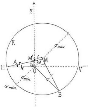
Blumenthal referred his readers to the diagram reproduced here as figure 6.8. The circle in the figure has center M and passes through the point H, which is at a distance I/2 from the origin O. (Notice that I/2 featured in the formula that Blumenthal chose to specify the transformation.) The off-center circle in the diagram is to be transformed by means of the Joukowsky formula and turned into a wing profile. The point H (sometimes called the “pole” of the transformation) is to be transformed into the all-important trailing edge. The radial line from M to H cuts the vertical axis at a point labeled M’. Then, explained Blumenthal, the distance OM’ (labeled f/2) controls the height of curvature of the wing, while the distance M’M (labeled 6) controls the thickness of the wing. In general, if the center of the circle to be transformed is on
the positive vertical axis, the result is one of Kutta’s arcs; if the center is on the positive horizontal axis, the result is a symmetrical rudderlike figure; if it is somewhere in between (as in fig. 6.8), the result will be a curved profile of the characteristic Joukowsky type. How curved and how rounded will depend on the factors that Blumenthal had just identified.
Blumenthal gave four examples of Joukowsky profiles to show the effects of modifying these parameters, that is, the effect of moving the center of the circle while ensuring that its circumference still passed through H. Thus the curvature parameter (expressed as the ratio f/l) was given the value of 0, 1/10, 1/5, and 1/5 (again), while the thickness parameter (expressed as the ratio 8/l) was set at 1/10, 1/20, 1/20 (again), and 1/50. The effect of these choices was clearly visible as the Joukowsky profiles that he illustrated went from a symmetrical shape to a markedly curved shape and from fat to thin.
From the velocity q of the flow (provided by Trefftz’s speedy method of graphical calculation), the pressure on the surface of the aerofoil could be
|
figure 6.8. Blumenthal identified the unifying principle behind Joukowskys separate treatments of the arc, the symmetrical rudder shape and the curved winglike shape. All of the shapes came from the same transformation formula applied to a circle that passed through a fixed point H on the y-axis. The shape produced depended on the position of M, the center of the circle. From Blumenthal 1913, 126. (By permission of Oldenbourg Wissenschaftsverlag GmbH Munchen) |
|
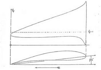
figure 6.9. One of Blumenthal s theoretically predicted pressure distributions along the upper and lower surface of a Joukowsky profile. The part of the graph above the dotted line shows the underpressure (the suction effect) on the upper surface of the wing. The lower graph shows the overpressure on the lower surface of the wing. From Blumenthal 1913, 128. (By permission of Oldenbourg Wissenschaftsverlag GmbH Munchen) |
computed, and this led to the most striking feature of Blumenthal’s paper. Each of the four Joukowsky profiles that he had constructed was accompanied by a graph showing the theoretical pressure distribution on the upper and lower surfaces. (In all cases Blumenthal assumed that the profile was at an angle of incidence of 6°.) One of his profiles and its accompanying pressure graph is shown in figure 6.9. Summing the areas enclosed by the graphs gave a quantity proportional to the resultant lift. Blumenthal discussed each aerofoil in turn, pointing out the significance of the predicted pressure distribution and its dependence on the parameters of the profile. Some features were common and stood out very clearly in the graphs, for example, the greater contribution of the suction effect on the upper surface of the wing compared to the pressure effect on the lower surface. Others were special to one shape, for example, the presence of a small suction effect even on the lower surface of the symmetrical (rudderlike) aerofoil and the very high speeds at the leading edge of the thinnest profile.


