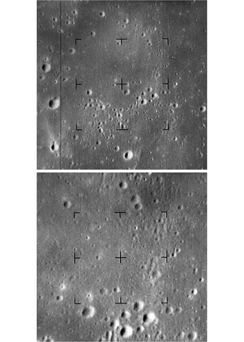
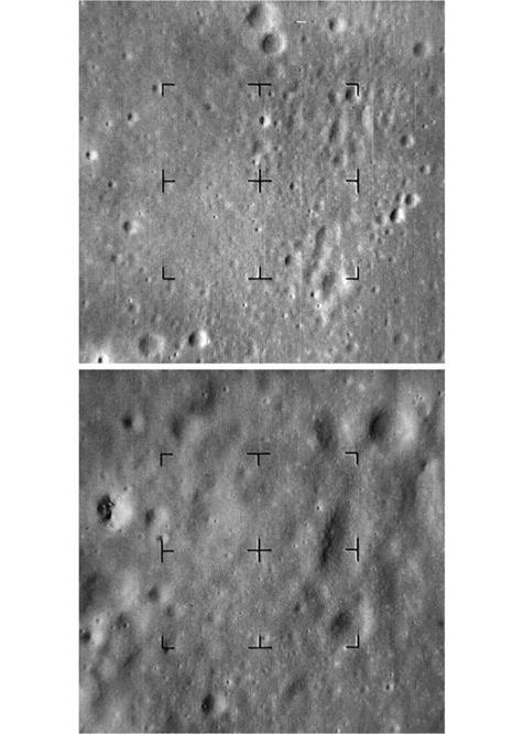
Category Paving the Way for Apollo 11

Ranger struggles

STRANDED

After Ranger 1 passed its qualification tests at JPL in May 1961, Oran Nicks, Chief of Lunar Flight Systems at NASA headquarters, authorised its transportation to Cape Canaveral, where the Air Force had assigned Hangar AE to the project. The launch window ran from 26 July to 2 August. In late June the Atlas was erected on Pad 12, the Agena added, and the spacecraft in its aerodynamic shroud installed to complete the stack. The combined systems tests of the fully assembled space vehicle were concluded on 13 July.

The countdown was delayed three days by a variety of problems, and was unable to start until the evening of 28 July with the intention of launching at dawn the next day, but a problem with the Cape’s electrical power supply meant that the clock had to be halted with 28 minutes remaining. After two other counts were frustrated, the attempt to launch on 2 August was abandoned when, as high voltage was applied to the spacecraft’s scientific instruments for calibration purposes, an electrical failure caused the explosive bolts to fire to deploy the solar panels inside the shroud. The spacecraft had to be retrieved and returned to the hangar. It was concluded that there had been an electrical arc to the spacecraft’s frame, but the precise source was not evident. The damaged parts were replaced. The launch was rescheduled for the start of the window for the next lunation.

The countdown began on the evening of 22 August and ran smoothly to liftoff at 10:04:10 GMT the next morning. With Ranger 1 on its way, James Burke became Mission Director at the Hangar AE command post.

The Atlas ignited its sustainer, the two side-mounted boosters and the two vernier control engines, and was held on the pad until verified to be running satisfactorily. For the first 2 seconds the vehicle rose vertically, and then it rolled for 13 seconds to swing its guidance system onto the flight azimuth. After 15 seconds the autopilot pitched the vehicle in that direction so as to arc out over the Atlantic. When a sensor detected that the acceleration had reached 5.7 times that of

Earth gravity,[20] about 142 seconds into the flight, the Atlas shut off its boosters, and 3 seconds later jettisoned its tail to shed 6,000 pounds of ‘dead weight’. The sustainer engine continued to fire. In the boost phase, the vehicle had been tracked by a radar at the Cape to enable the Air Force to calculate its initial trajectory, and as the sustainer flew on it acted upon steering commands radioed by the ground. When the sustainer shut down, the two verniers on the side of the Atlas fired as appropriate to refine the final velocity. As it did not have the power to insert the Agena directly into orbit, the upper stage was to be released on a high ballistic arc. Once free, the Agena, now above the dense lower atmosphere, jettisoned the aerodynamic shroud to shed dead weight, and ignited its engine. ft then achieved the desired circular parking orbit at an altitude of 160 km. Meanwhile, the Air Force’s computer processed the tracking provided by the radars of the downrange stations of the Eastern Test Range in order to calculate the length of time the Agena should spend in parking orbit and the parameters required for its second manoeuvre. This information was transmitted to the vehicle.

The plan for this test flight was for the Agena В to use its second burn to enter an elliptical orbit with an apogee of 1 million km, far beyond the orbit of the Moon, and for simplicity the orbit would be oriented not to venture near the Moon. The primary objective was to evaluate the spacecraft’s systems in the deep-space environment, in particular its 3-axis stabilisation using Earth, Sun and star sensors, the pointing of its high-gain antenna, and the performance of the solar panels. Each Block f Ranger was expected to have an operating life of several months, and to provide worthwhile data for the sky scientists.

After its second burn, the Agena was to fire explosive bolts in order to release the spacecraft, which would be pushed away by springs. Then the spent stage was to use its thrusters to make its trajectory diverge. Radio interference prevented the tracking site at Ascension fsland in the South Atlantic from monitoring the reignition. When Johannesburg reported detecting the spacecraft several minutes ahead of schedule, it became evident that the second burn had failed and the spacecraft was still in a low orbit. When Goldstone picked it up, the orbit was calculated to have a perigee of 168 km and an apogee of 500 km. Although the Agena had reignited, it had shut down prematurely and then released the spacecraft. ft was encouraging that the spacecraft had deployed its solar panels, locked onto the Sun, rolled to acquire Earth and then deployed its antenna, but because it was ‘stranded’ in a low orbit it soon entered the Earth’s shadow and lost both power and attitude lock. On re-emerging into sunlight it fired its thrusters to restabilise itself. This occurred on every shadow passage, with the result that after only one day the nitrogen was exhausted and, unable to stabilise itself to face its solar panels to the Sun, the battery, intended only for launch and the brief midcourse manoeuvre, expired. The inert spacecraft re-entered the atmosphere on 30 August.

A study of the telemetry tapes confirmed that the Agena reignition sequence had started at the proper time, but almost immediately the flow of oxidiser had ceased. The small amount of oxidiser which had entered the engine gave the 70-m/s velocity

Stranded 91


Preparing the Ranger 1 spacecraft.


image42

increment that slightly raised the apogee. The premature cutoff was classified as a one-off failure.

Although Ranger 1 flew in an environment different to that intended, its designers were encouraged that it had correctly deployed its appendages and (repeatedly) been able to adopt cruise attitude. But the sky scientists received nothing of value from the mission.

On 5 October, as a result of lessons learned from Ranger 1 when various lines of authority had penetrated the Space Flight Operations Center, Marshall Johnson was appointed Chief of the Space Flight Operations Section and, with it, sole authority to direct the control team while a mission was underway.

The launch window for Ranger 2 was 20-28 October 1961. The tests on the fully assembled space vehicle on Pad 12 were completed on 11 October. The countdown began on time in the evening of 19 October, but was scrubbed with 40 minutes on the clock owing to a fault with the Atlas. Although this was readily repaired, the fact that another Atlas was due to leave from another pad the next day meant Ranger 2 had to wait. The countdown on 23 October was abandoned because of another issue with the Atlas. At this point, a Thor-Agena B launched from Vandenberg Air Force Base in California was lost as a result of the failure of the hydraulics of the Agena’s engine, and NASA decided to await the outcome of that investigation. The problem was diagnosed and fixed in time for the next window, and Ranger 2 lifted off on the first attempt at 08:12 GMT on 18 November. As before, the spacecraft rose above the horizon at Johannesburg early, indicating that the second burn had failed – this time without even producing a modest apogee. Ranger 2 performed perfectly, but it was doomed and re-entered the atmosphere on 19 November.

An Air Force analysis of the telemetry indicated that the roll gyroscope of the Agena B’s guidance system had been inoperative at liftoff, most probably due to a faulty relay in its power supply. The attitude control system had compensated for the roll control failure by using its thrusters, and in so doing had exhausted the supply of gas. As a result, the Agena had tumbled in parking orbit. This caused the propellants to slosh in their tanks, which in turn prevented them from flowing into the engine when it tried to reignite. On 4 December 1961 the Air Force informed NASA of its findings, and Lockheed promised to report within a month on how it would fix the fault. When NASA decided in December 1959 to use the Agena B, it had presumed the Air Force would have worked the bugs out of the vehicle by the time it was needed, but only one had been launched prior to Ranger 1 and, in effect, NASA was testing it for the Air Force!

Although some aspects of the Block I tests had not been achieved, the engineers at JPL were encouraged that on both occasions the spacecraft had worked as well as could be expected in the circumstances. If the Agena was fixed as soon as Lockheed hoped, then it should be possible to proceed with Ranger 3 as planned.

TUMBLING OUT OF CONTROL

Since Surveyor 2 was essentially complete at the time of the first mission, it was identical to its predecessor. Upon the surprising success of Surveyor 1, NASA opted not to postpone the second mission to install scientific instruments. It duly lifted off from Pad 36A at 12:32:00 GMT on 20 September 1966 on a direct-ascent trajectory with the objective of landing in Sinus Medii.5 In general, this was much rougher – looking than the area in Oceanus Procellarum assigned to Surveyor 1. This time, it was intended to operate the downward-looking TV camera during the approach in order to gain a sense of perspective of the landing site.

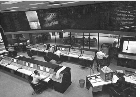
The translunar injection trajectory would intercept the Moon just northeast of the crater Mosting on the western margin of Sinus Medii, 142 km from the centre of the 60-km target circle. The sequence for the 31.5-ft/sec midcourse manoeuvre began at T+15h 42m with an interrogation to verify the readiness of the vehicle’s systems. At 16h 12m the spacecraft initiated a roll of +75.3 degrees, followed 5 minutes later by a yaw of +11.5 degrees. This successfully oriented the vehicle for the burn. The burn was started on command at 16h 28m but vernier no. 3 failed to ignite. After the specified duration of 9.8 seconds, the system shut down. The asymmetric thrust had left the vehicle spinning about one axis at 1.22 revolutions per second, with this axis precessing in 12 seconds. This saturated the gyros in the minus pitch, plus yaw and minus roll directions. The flight control system set about regaining stability utilising the attitude control thrusters. After 7 minutes the precession had been cancelled. But after 14 minutes, with a residual spin around the main axis of 0.85 revolutions per second and with the jets having consumed half of the nitrogen supply, a command was sent from Earth to inhibit the system and save the remaining gas for use in the event that the problem involving vernier no. 3 could be overcome, at which time the verniers would be used to stabilise the vehicle.

Подпись: 5In fact, this was site I-P-5 on Lunar Orbiter 1’s target list.

image108Deep Space Instrumentation Facility automatic gain control variations served to document the initial tumbling of the Surveyor 2 spacecraft.

image109SOLENOID-OPERATED PROPELLANT VALVE

TUMBLING OUT OF CONTROL

OXIDIZER

TANKS


HELIUM

TANK


TUMBLING OUT OF CONTROL

TUMBLING OUT OF CONTROL

Подпись: THROTTLING VALVE ASSEMBLY

RELIEF VALVE

FUEL TANKS

A simplified depiction of the Surveyor spacecraft’s vernier propulsion system.

MOLYBDENUM NOZZLE

image111


image110

Detail of an engine of the Surveyor spacecraft’s vernier propulsion system.

The solar panel was unable to provide power while the vehicle was tumbling, so time was of the essence. It was apparent that verniers no. 1 and 2 had delivered the specified thrust during the manoeuvre, but no. 3 had delivered no thrust at all. It was decided to command a 2-second firing in an effort to clear vernier no. 3. This was done at 18h 56m and again at 19h 18m, but without success. In case the fault was a stuck flow regulator valve, the system was commanded to pulse five times for a duration of 0.2 seconds at 5 minute intervals starting at 31h 12m and then attempt another 2-second firing – again in vain. This sequence was repeated at 26h 28m, 37h 29m, 38h 45m and 39h 45m – each time with no effect. At 41h 11m an attempt was made to fire the engine at a ‘harder’ start and a higher thrust for 2 seconds. Because the other two verniers were participating in these tests, by this point the spin rate had increased to 1.54 revolutions per second. At 43h 13m a new sequence was initiated in which the engines were pulsed five times for 0.2 second with 1 minute between firings, as a preliminary to a 20-second firing. Although this time the temperature of vernier no. 3 increased somewhat, the engine did not respond properly.

Although the spacecraft was tumbling out of control, it was decided to undertake a series of tests to obtain engineering data on its subsystems, concluding at 45h 02m with a command to trigger the retro sequence. Contact was lost 30 seconds into the retro-rocket’s burn. The inert vehicle would have struck the Moon several hundred kilometres southeast of Copernicus.

The post-flight investigation by propulsion engineers of JPL, NASA, Hughes and Thiokol decided that there had been no combustion in vernier no. 3 at the attempted midcourse manoeuvre, and that although fuel had flowed into the engine the oxidiser had not. As it was not possible to determine the root cause of the failure, a number of revisions were introduced for Surveyor 3 designed to provide better diagnostics of the vernier propulsion system, both during pre-flight testing and in flight.

Apollo picks up the pace

MOON ROCKET

On 19 January 1959 NASA took over the Air Force’s contract with Rocketdyne for the development of the F-1 kerosene-burning engine. The prototype was test fired on

10 February 1961. By sustaining 1.55 million pounds of thrust for several seconds, it broke the record for a single-chamber engine by a considerable margin. On 9 April 1961 it was announced that the engine had achieved 1.64 million pounds of thrust. On 26 May 1962 the engine was fired at full power for its intended operating time of 150 seconds. Meanwhile, Rocketdyne began the development of the 200,000-pound- thrust hydrogen-burning J-2 engine that was to power the upper stages of the Saturn launch vehicle. The first full-duration test of this engine was on 27 November 1963. The Douglas Aircraft Corporation fired an S-IVB stage utilising a single J-2 engine at full power for 10 seconds on a static rig at its Sacramento facility on 4 December 1964. But it was a ‘battleship’ variant (equivalent to a ‘boilerplate’ for a spacecraft) having tankage made of thick stainless steel instead of the lightweight aluminium of the operational vehicle. On 7 December 1964 the first S-IVB mockup – which was accurate in terms of mass, centre of gravity and structural stiffness, but with models of the engine and other systems – was delivered to the Marshall Space Flight Center for stress testing. On 16 April 1965 the first S-IC stage utilising five F-1 engines was test fired for several seconds at NASA’s Mississippi Test Facility. On 24 April the S-

11 stage utilising five J-2 engines was test fired at Rocketdyne’s facility at Santa Susana in California. On 5 August the S-IC made a full-duration test during which it responded to steering commands provided by the blockhouse. On 9 August the S-II made its first full-duration firing. That same day the first production version of the S-IVB was tested, and on 20 August it was fired for 3 minutes, shut down for half an hour and reignited for almost 6 minutes in a simulation of its role on a lunar mission.

Unfortunately, by early 1966 the development of the S-II had slipped. In an effort to recover, North American Aviation hired a new manager, Robert E. Greer, who took a team of engineers to the Mississippi Test Facility. On 23 April 1966 the S-II was successfully fired for 15 seconds, but faulty instrumentation caused premature

cutoffs on 10, 11 and 16 May. It fired for 150 and 350 seconds in tests on 17 and 20 May. But fires broke out in two places on the vehicle in a test on 25 May, and as the stage was being removed from the stand three days later its hydrogen tank exploded, damaging the facility and injuring five people. George Mueller in Washington began to send weekly progress reports on the S-II to company president Leland Atwood, at one point advising him that the S-II had an excellent chance of replacing the LM as the ‘pacing item’ in the program.

But then the fire that killed the Apollo 1 crew during a supposedly routine test of the spacecraft on 27 January 1967 halted the program in its tracks. Nevertheless, the time taken to redesign the CSM provided the opportunity for the development of the Saturn V and the LM to catch up.

On 17 April 1967 the Manned Spacecraft Center proposed a minimum of three manned Saturn V missions involving both the CSM and the LM prior to attempting the lunar landing. When George Mueller advocated landing on the third mission, Chris Kraft warned George Low that a landing should not be tried ‘‘on the first flight which leaves the Earth’s gravitational field’’ because flying to the Moon was such a great step forward in terms of operational capability that this should be demonstrated separately, to enable the landing crew to focus on activities associated with landing. Accepting Kraft’s argument, on 20 September Low led a delegation to Washington. Owen E. Maynard, Chief of the Systems Engineering Division in Houston, outlined a step-by-step sequence: (A) Saturn V and unmanned CSM development; (B) Saturn IB and unmanned LM development; (C) Saturn IB and manned CSM evaluation; (D) Saturn V and manned CSM/LM joint development; (E) CSM/LM trials in an Earth orbit involving a ‘high’ apogee; (F) CSM/LM trials in lunar orbit; (G) the first lunar landing; (H) further ‘minimalist’ landings; (I) reconnaissance surveys in lunar orbit; and (J) ‘enhanced capability’ landings.[48] This alphabetically labelled series was not a list of flights, as several flights might be required to achieve one mission. Two Saturn V development flights were already scheduled as Apollo 4 and Apollo 6, and the LM-1 flight as Apollo 5. Sam Phillips asked whether a second Saturn V test was really necessary, and Wernher von Braun said the second would serve to confirm the data from the first. If the Saturn V development were to prove to be protracted, then the ‘D’ mission would be done by reinstating the plan in which the CSM and LM would be launched individually by Saturn IBs and rendezvous in orbit. Most of the discussion was devoted to the proposal for a lunar orbital flight ‘‘to evaluate the deep space environment and to develop procedures for the entire lunar landing mission short of LM descent, ascent and surface operations’’. When Mueller argued ‘‘Apollo should not go to the Moon to develop procedures’’, Low said that developing crew operations would not be the

main reason for the mission; there was actually still a lot to be learned about navigation, thermal control and communications in deep space. Although the meeting left this matter undecided, the alphabetic labels soon became common shorthand.

Sam Phillips confirmed on 2 October 1967 that LM-2 should be configured for an unmanned test flight, and directed that LM-3 be paired with CSM-103 for the first manned mission of the complete Apollo configuration.2 Grumman’s latest schedule called for LM-2 to be delivered in February 1968, LM-3 in April and LM-4 in June. On 4 November George Mueller issued the schedule for 1968: AS-204 with LM-1; then AS-502 as the second unmanned test; AS-503 as the third unmanned test, if this proved necessary; AS-206 with LM-2, if required; AS-205 with CSM-101, manned; and AS-504 with CSM-103 and LM-3, manned. On 15 November George Low said that in the event of AS-503 being unmanned, the payload should be the ‘boilerplate’ spacecraft BP-30 and lunar module test article LTA-B.

STRATIGRAPHIC MAPPING

In April 1957 the National Academy of Sciences awarded Kuiper the funding to start work on a new lunar atlas, and supplementary money was provided later in the year by the Air Force. The resulting Photographic Lunar Atlas was published in I960. The best available photographs were printed on a scale at which the lunar disk spanned 2.5 metres. It formed a striking contrast to the similarly sized map based on visual observations that was published in 1959 by H. P. Wilkins of the Lunar Section of the British Astronomical Association. Although very different in presentation, the two maps were comparable near the centre of the Moon’s disk but even in the best pictures the limb regions were marred by ‘seeing’, and it was in these areas that the visual observers had the advantage. However, the pictures were able to be projected onto a white globe and rephotographed to eliminate foreshortening and thereby gain a new perspective of the limb regions. This Rectified Lunar Atlas was issued in 1963 as a supplement to the 1960 atlas.

In 1959 the Air Force Chart and Information Center in St Louis, Missouri, began to use airbrushing to represent topography on a scale of 1:1,000,000 for a series of Lunar Astronautical Charts. Meanwhile, the Army Map Service issued ‘photomaps’. The US Geological Survey wished to map the Moon geologically. The first step was to identify the various distinct geological units in terms of their textures, delineate their outlines on a ‘base map’, and use the principle of superposition (as defined by Nicolas Steno in 1669) to determine the order of their deposition. The objective was to obtain insight into the history of the lunar surface. In 1960 Robert Hackman of the Photogeology Branch of the Survey in Washington DC demonstrated that it was possible to apply stratigraphic analysis to the Moon. When issued in 1961, his map of what he referred to as pre-maria, maria and post-maria units marked a significant departure from the astronomers’ means of mapping. The superposition relationships suggested to Hackman that the maria were volcanic, not splashes of impact melt. He drew attention to a patch of light-toned material between the Apennine mountains and the crater Archimedes. There was ejecta from Archimedes on this patch, and the dark mare had encroached upon the ejecta. The sequence was clear: the light-toned material was the floor of the cavity created by the Imbrium impact, this had been hit by Archimedes some time later, and the mare had appeared after that. Since the light patch was sufficiently elevated not to be overrun, he named it the Apennine Bench. A factor of two difference in the cratering densities of the bench and the adjacent mare was evidence that a significant interval had elapsed between the Imbrium impact and the appearance of the mare within the cavity.

Meanwhile, Gene Shoemaker had independently made a stratigraphic study of a section of the Moon to demonstrate the technique. Visiting a bookstore shortly after being shown the prototype Lunar Astronautical Chart of the Copernicus area, he had happened across a picture of this area taken by Francis Pease in 1919 while testing the 100-inch telescope at Mount Wilson. It was of sufficient clarity to show craters down to 1 km in diameter, so Shoemaker had it enlarged and set to work. Whereas Hackman had used only pre-maria, maria and post-maria units, Shoemaker mapped seven units, which he named the pre-Imbrian, Imbrian, Procellarian, Eratosthenian

Stratigraphic mapping 29

and Copernican systems. In essence the Eratosthenian and Copernican corresponded to Hackman’s post-maria, but Shoemaker distinguished the Eratosthenian from the Copernican because rays from Copernicus were superimposed on the Eratosthenes ejecta – in effect, the difference was whether a post-mare crater’s rays were fresh, or faded. On 17 March I960 Shoemaker presented a paper showing that whereas much of the material excavated by Copernicus had been ‘hinged’ to produce the rim and adjacent blanket of ejecta, some of the material was hurled ballistically and fell further out, where its impact made distinctive chains of small secondary craters. The secondary craters were less energetic because, to have fallen back at all, the ejecta could not have exceeded the escape velocity – which is an order of magnitude lower than the typical cosmic velocity of material arriving from space. This study not only established Copernicus to be an impact crater, it also refuted the assertion by the advocates of the volcanic origin of craters that the chains of small craters marked eruptions along fractures in the crust.

At the International Astronomical Union Symposium in December 1960, which was a major event for astronomers, Shoemaker and Hackman presented a joint paper entitled Stratigraphic Basis for a Lunar Time Scale. This laid the foundation for how geological units could be recognised on an extraterrestrial surface and placed into a stratigraphic sequence. In the case of Earth the units were identified by studies in the field, but for the Moon they would have to be inferred from overhead imagery – at least until expeditions were made to the lunar surface.

Having established that the maria were formed after the Imbrium impact, it was expected that all maria would be able to be assigned to the Procellarian system, but in late 1963, when patches of mare were found to be stratigraphically younger than craters attributed to the Eratosthenian system, the Procellarian system was dismissed and each mare unit was assigned to the system implied by its particular stratigraphy.

Also in late 1963, the scheme was refined by the introduction of formation names for the geological units. The reason for the change was that a formation name was objective, and did not imply a specific physical process. Also, because a formation defined a terrain type by its texture, it did not require to be contiguous. This was the case for the hummocky material peripheral to Imbrium. It had just been mapped by Richard Eggleton, who had transferred to Shoemaker’s team from the Engineering Geology Branch. It was labelled the Fra Mauro Formation, after a prominent crater within it. Although there was little doubt that it was Imbrium ejecta, to have labelled it as such would have been subjective and would have set a poor precedent.

In September 1961 Gerard Kuiper convinced the Air Force Chart and Information Center to exploit visual observations in compiling the Funar Astronautical Charts, since in moments of good ‘seeing’ the eye can resolve finer detail than is able to be recorded during a photographic exposure. The pictures were to provide the basis for mapping and the visual observations would provide the detail. On joining the team, each ‘astrogeologist’ was assigned a quadrangle to map geologically, in addition to his principal task. As one of the first such recruits, Eggleton provided training for those who followed. Observing time was allotted when the terminator was near the assigned area, to emphasise subtle topography. Those in Arizona used the 24-inch refractor of the Fowell Observatory in Flagstaff,

and those in Menlo Park used the 36-inch refractor of the Lick Observatory on Mount Hamilton near San Jose.

In February I960 the University of Arizona in Tucson established the Lunar and Planetary Laboratory, and made Gerard Kuiper its head. When William Hartmann joined in mid-1961, he assisted the team which was producing the Rectified Lunar Atlas. A major finding was the existence of systems of concentric rings. These had not been recognised from Earth owing to foreshortening, but when viewed from an ‘overhead’ perspective they stood out clearly. The most spectacular case surrounded a small dark patch which was itself only glimpsed at times of favourable libration and had been named Mare Orientale for the reason that it was on the eastern limb – a rationale rendered obsolete by the decision of the International Astronomical Union in August 1961 to switch the east and west limbs! On realising that the multiple-ring structures were a distinct class of geological feature, Hartmann introduced the term ‘basin’. He wrote up the discovery with Kuiper and published in-house on 20 June 1962 in the paper Concentric Structures Surrounding Lunar Basins. Soon, similar patterns were identified in degraded states around a dozen ‘circular maria’. This insight revealed the true violence of a basin-forming impact. Namely, a vast impact excavated a cavity, forming one or more concentric rings of mountains composed of individually faulted blocks with their steep ‘fronts’ facing inwards, whilst also piling up material in blankets immediately beyond and etching sculpture as ballistic ejecta fell further out – all of which occurred literally in an instant. Some time later, and perhaps after a considerable interval, lava rose through deep fractures in the cavity of the basin to flood it, often to a depth sufficient to submerge the inner rings. As a result, a basin consisted not only of the cavity, but also the concentric rings, the inner blankets of ejecta and the outer sculpture. The clear fact that a basin was distinct from the mare that formed later was highlighted by the discovery of concentric rings around large craters which had not been fill with mare. Since multiple-ring structures were not of volcanic origin, this lent support to the case for smaller craters also being of impact origin. In fact, although it was recognised early on that sculpture was gouged by the fall of material thrown out on shallow-angle trajectories, it was a while before it was realised that a lot of basin ejecta must have struck at a high angle and, consequently, many well-known sizeable craters are probably not primary impacts but secondaries from basin-forming events. By 1963, photogeologists were working to determine the order in which the dozen or so recognised basins were formed.

In just a few years, therefore, an examination of the Moon by geologists applying standard mapping methods had provided insights into the history of the lunar surface which had eluded astronomers for centuries.

LUNAR FLYBY

In May 1961 Aeronutronic began to drop balsa encapsulated ‘survival capsules’
containing sterilised systems immersed in viscous fluid from aircraft flying over the Mojave Desert – with disappointing results: those that fell on rocky ground failed to operate. Further tests in October showed that even seismometers which survived the impact often suffered electronic issues. With the launch of Ranger 3 only months away, this was disconcerting. On 6 November 1961 Don B. Duncan replaced Frank Denison in charge of developing the capsule. NASA issued heat-treatment waivers for the most sensitive components of the radar altimeter, retro-rocket and capsule. In 1961 Albert Hibbs, Chief of the Space Sciences Division at JPL, appointed Harold W. Washburn as Ranger Project Scientist to liaise between the spacecraft engineers and the experimenters and coordinate their activities during a mission.2

Meanwhile, after the Ranger 3 bus was assembled at JPL in July 1961 it suffered much greater component failure rates than the case of the proof-test model, with the only difference between them being heat-sterilisation. NASA issued further waivers for the most sensitive components. ft was clear that the sterilisation process efficacy specified in 1960 was unattainable. On 15 November NASA formally accepted the repaired bus. ft was driven by truck in an environmentally regulated container, and arrived at the Cape on 20 November. On 6 December Oran Nicks opined to Edgar Cortright that one of the three Block ff flights would be successful, and one, perhaps two, of the four Block fff flights. This underscored the perceived technological risk of the venture. James Burke expected one of each to be a fully successful flight. On 2 January 1962 Clifford Cummings told Robert Seamans that it was “likely that the sterilization procedures have compromised spacecraft reliability”. However, when Lockheed announced that it had fixed the problem with the Agena B, NASA decided to try to launch Ranger 3 on schedule.

The major objectives for the mission were to perform the midcourse and terminal manoeuvres. Given the performance of its predecessors, it was fully expected that on being set free by the Agena, Ranger 3 would deploy its appendages and adopt cruise attitude. ff it flew to the Moon as planned, then Burke’s engineers would be content. ff the surface package functioned properly, this would constitute a bonus – if not, the package would have two more opportunities to achieve its scientific objectives.

Although it would be a considerable technical feat to reach the Moon at all, and in a sense anywhere would satisfy the mission, the trajectory was very limited. The fact that the retro-rocket of the surface package could not deal with a lateral velocity component meant the bus needed to make a vertical descent over the target. This, in turn, meant a site near the equator on the leading hemisphere. Prior to the space age, astronomers had defined lunar longitude in terms of how the Moon appeared in the terrestrial sky, with the leading limb (i. e. the one that faces the Moon’s direction of travel as it pursues its monthly orbit of Earth) being east. However, in August 1961 the fnternational Astronomical Union had redefined the system to match the point of view of an observer on the lunar surface, with east in the direction of sunrise; thus reversing the old scheme. For a Ranger Block ff the

Подпись: 2fn 1963 Thomas Vrebalovich would succeed Washburn as Ranger Project Scientist at JPL.

target would therefore have to be in the western hemisphere. In fact, a vehicle launched from Florida would expend less energy in approaching Oceanus Procellarum between 10 and 50 degrees west of the meridian and within 16 degrees of the equator than it would for any other region. Because the Moon maintains one hemisphere facing towards Earth, at any given site Earth remains in a more or less fixed position in the sky. The target could not be so far towards the limb that at unfavourable librations the signal from the surface would be too weak to be read. Another constraint was that the timing had to be such that the Moon was visible to Goldstone when the bus transmitted its scientific data. The phase of the Moon would be ‘full’ on 20 January 1962 and ‘last quarter’ on 28 January. The window was set for 22-26 January. If Ranger 3 managed to lift off on the first day, it would make its approach on 25 January.

After Ranger 3 completed its final systems checks in Hangar AE, it was driven to Pad 12 on 18 January and installed on its launch vehicle. When kerosene was loaded into the Atlas on 19 January, a leak was discovered in the bulkhead between the fuel tank and the liquid oxygen tank. Over the next few days the Air Force removed the centre engine and built a wooden frame up through the exposed aperture at the base of the fuel tank in order to allow technicians wearing masks and oxygen cylinders to replace the ruptured bulkhead. This round-the-clock effort made the vehicle ready in time to attempt to launch on the last day of the window. Meanwhile, as this was the first mission of the project intended to reach the Moon, the spacecraft was sealed in the aerodynamic shroud atop the Agena and bathed in gaseous ethylene oxide for 11 hours as the final stage of the sterilisation process, then the shroud was purged with dry nitrogen passed in through a sterile filter.

The countdown on 26 January proceeded smoothly, and Ranger 3 was launched at 20:30 GMT. The Air Force tracked its ascent and calculated the steering commands, but when these were transmitted to the Atlas it failed to act on them. The autopilot flew on, ignorant of deviations from the planned trajectory. In particular, it was not possible to command the moment of shutdown to optimise the final velocity, and when the autopilot ordered this using its programmed parameters it was both higher and faster than required. As a result of this discrepancy, the parking orbit attained by the Agena was slightly different to that planned. The limited ability of the spacecraft to correct its trajectory meant that in making the translunar injection the Agena had to pass through a ‘key hole’ in the sky that was only 16 km wide, and attain a speed which differed from the desired 40,000 km/hour by no more than 25 km/hour. In the event, Woomera’s tracking indicated that the spacecraft would cross the orbit of the Moon at a point 32,000 km ahead of that body – a discrepancy which exceeded the spacecraft’s 44-m/s midcourse manoeuvre cap­ability. Nevertheless, engineers were encouraged that Ranger 3 had deployed its solar panels, locked onto the Sun, rolled to acquire Earth and then deployed its high – gain antenna. The flight would provide an opportunity to evaluate the spacecraft’s performance in deep space, essentially as had been intended for the Block I.

James Burke flew from the Cape to JPL to operate the spacecraft from the Space Flight Operations Center. It was decided to exercise all of the functions, including the midcourse and terminal manoeuvres. It was not possible to test the retro-rocket

image43

Preparing the surface package subsystem of the Block II Ranger spacecraft.

of the surface package, since its separation from the bus could be triggered only by its own radar altimeter. On 27 January the sequence of commands was uplinked for a midcourse manoeuvre designed to reduce the flyby range. Ranger 3 executed the preliminary roll and pitch changes as specified, fired its engine, then resumed cruise attitude. However, tracking revealed that the burn was the opposite of that intended and had increased the miss distance to 36,750 km. The error was an inverted sign in the computer program used by JPL to calculate the burn. Regardless of the outcome, the engineers were delighted that the spacecraft had made a manoeuvre and resumed its cruise attitude. Shortly after this, the boom holding the gamma-ray experiment completed its deployment. It had hinged down after separation from the Agena, and now, as planned, a gas generator extended it in a telescopic manner. The instrument was able to calibrate the emissions by the spacecraft and then make the first direct measurement of the flux of gamma rays in space.

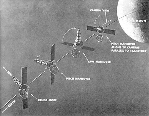
A plan had been devised to perform a terminal manoeuvre which would orient the spacecraft to enable it to photograph the Moon during the flyby – in much the same manner, in fact, as had been intended for some of the Pioneer probes. In this case, it would view the illuminated leading hemisphere, and reveal that portion of the far – side which was in darkness for Luna 3 in 1959. The unplanned trajectory meant that Ranger 3 drew close to the Moon on 28 January. The cover for the optics was commanded to open, and power was applied to warm up the TV system. Goldstone uplinked the commands for the terminal manoeuvre to turn the spacecraft in order to point the camera at the Moon. The inverted sign had been corrected prior to making the calculation. An hour later, the spacecraft was told to make the manoeuvre. It initiated the pitch change in the correct direction, but soon thereafter the downlink began to intermittently drop out – a computer/sequencer fault had denied the vehicle the use of its Earth and Sun sensors, the gyroscopes directing the turn did so in an uncontrolled manner and the spacecraft was left spinning. At the appointed time, the TV system took pictures. Some frames were received at a very weak signal strength, and the fact that it was possible to see the black reference marks on a pane of glass in front of the focal plane silhouetted against a soft glow of sunlight glinting off the structure of the spacecraft provided welcome confirmation to the engineers from the Radio Corporation of America that their system had worked. At 23:23 GMT, some 6 hours after the attempted manoeuvre, Ranger 3 crossed the orbit of the Moon and passed on into solar orbit.

On 8 February 1962 JPL informed Oran Nicks of the preliminary findings of its investigation into the loss of Ranger 3. It had been concluded that the malfunction of the computer/sequencer was a result of the heat treatment required for sterilisation. It would therefore be necessary to issue waivers for the components believed to have failed. Although the mission had not reached the Moon, it had nevertheless provided an opportunity for the flight control team to compute a deep-space trajectory and then uplink the commands for a midcourse manoeuvre, which the spacecraft – the most sophisticated American deep-space vehicle to date – had executed as directed. The engineers were therefore confident that the next mission would reach the Moon.

Meanwhile

Homer Newell’s Space Sciences Steering Committee decided on 1 December 1961 to consolidate the TV experiments of the Block II and Block III versions of Ranger. Previously, Gerard Kuiper, Gene Shoemaker and Harold Urey had been named to receive and interpret such pictures as were returned by the Block II flights – having played no part in the development of the camera. Now it was decided that they should form a team, together with Ray Heacock of the Space Sciences Division at JPL, and work with the Radio Corporation of America in the development of the high-resolution TV system for the Block III. In effect, Newell wished to integrate the engineers and scientists at the project level at JPL to match the recent integration at the program level in Washington, in the expectation that this would enhance the scientific results. Unfortunately for James Burke, in early 1962 Newell also sought to augment the Block III to recover some of the particles and fields research lost on the Block I flights. On 14 March 1962 the Steering Committee decided to add eight experiments to the Block III. Burke learned of this from Oran Nicks on 20 March. The solar panels of the Block I and Block II were triangular with truncated tips. It was necessary to fit larger rectangular panels to provide the power to operate all the additional Block III experiments.

The Apollo zone

RECONNAISSANCE FLIGHTS

Only 28 months elapsed between James Webb approving the Boeing contract for Lunar Orbiter and the first mission. It had been hoped to launch on 11 July 1966, but Eastman Kodak was late in delivering the photographic system and the launch was rescheduled for 9 August. At the Cape, the Air Force made available Hangar S for the project. The photographic system was installed on 1 August, and the next day the spacecraft was mated with its Atlas-Agena D on Pad 13. At this point, a Deep Space Network facility at the Cape verified the spacecraft’s communication system.

The countdown on 9 August was scrubbed at T-7 minutes owing to an anomaly with the Atlas, but liftoff occurred at 19:26:01 GMT on 10 August. The spacecraft’s launch mass was 387 kg – which was at the top end of the launcher’s capability for a deep-space mission. The Agena made a 154.5-second burn to achieve insertion into parking orbit at an altitude of 190 km at 19:34:44. It reignited at 20:02:35 to perform the 89-second translunar injection manoeuvre.

Following its release at 20:06:48, Lunar Orbiter 1 deployed its solar panels and antennas, then acquired the Sun for the first step towards adopting its cruise attitude. Some 6 hours into the translunar coast, the spacecraft was ordered to roll in order to locate the star Canopus, but it failed to lock on. The sensor was being distracted by sunlight reflecting off the vehicle’s structure – a possibility that really ought to have been ‘designed out’. The vehicle was commanded to turn to point the sensor at the Moon to provide a second point of reference to initialise the inertial system.

The midcourse manoeuvre of 38 m/s was achieved by a 32-second burn started at 00:00 on 12 August. When its interior began to overheat, the vehicle was instructed to swing its main axis 36 degrees off-Sun. This thermal problem came as a surprise, because Boeing had subjected the design to thorough testing in the vacuum chamber at its Kent Test Facility in Seattle. The Canopus sensor was finally able to lock on at 13:50 on 13 August.

The trajectory was so accurate that the vehicle arrived within 10 km of the desired

orbit insertion point. The command for the insertion manoeuvre was sent at 15:23 on 14 August, after a cruise of 92 hours as against 66 hours for Ranger. After adopting the requisite attitude, the spacecraft began the burn at 15:34, firing its engine for 579 seconds in order to slow down by 790 m/s and enter a 190 x 1,860-km orbit that was inclined at 12.2 degrees to the lunar equator and had a period of 3 hours 37 minutes. As viewed from an imaginary vantage point above the Moon’s north pole, the orbit was anticlockwise. Shortly after insertion, the vehicle disappeared around the Moon’s trailing limb.

On 15 August Lunar Orbiter 1 read out the pre-exposed test frames on the leader of its film strip. These had been read out during ground trials at Goldstone to verify the functionality of the scanning and communication system. This in-flight readout was to confirm that the entire apparatus, both in space and on Earth, was functioning properly. By now, the thermal problem had become acute. The paint on the base of the vehicle was meant to absorb heat while exposed to sunlight and radiate it back to space while in the shadow of the Moon, but it seemed the pigment was deteriorating. However, on 18 August an electrical issue had the beneficial side – effect of easing this overheating problem.

The phase of the Moon was ‘new’ on 16 August; ‘first quarter’ would occur on 23 August and ‘full’ on 31 August. As the alignment of the spacecraft’s perilune would remain fixed relative to the stars, the longitude of perilune would migrate westward at a rate of 12 degrees per 24 hours as the Moon travelled around Earth. This meant that the spacecraft could photograph a succession of sites along the equatorial zone with the Sun at essentially the same elevation in the sky. The Canopus sensor would routinely recalibrate the inertial system to ensure that the camera was accurately aimed.

After advancing the film to its start point, the camera snapped its first pictures on 18 August. It viewed Mare Smythii, near the equator on the eastern limb. Although outside the Apollo zone, this area was of interest for selecting landmarks to assist in Apollo orbital navigation. In this case, the spacecraft was at an altitude of 246 km, its velocity relative to the surface was 6,400 km/hour, the shutter setting was 1/50th second, and the frame pairs were taken at 10-second intervals. These frames were processed and 5 hours later were scanned travelling forward through the system. The M frames were of excellent quality, but it seemed that the focal-plane shutter of the narrow-angle optics was out of synchronisation with the V/H sensor, smearing the H frames. To investigate the problem, it was decided to take additional pictures using different shutter speeds, both with and without the V/H sensor operating. The results confirmed the sensor to be inoperative. A further test was made in which the output voltage of the sensor was increased in the hope of engaging the shutter, but this did not work. An analysis of the telemetry showed that the logic control circuitry of the focal-plane shutter was susceptible to electromagnetic interference that made it fire at the wrong point in the motion-compensation cycle, and this was a problem which could not be overcome in flight.

Since the H frames were essential to addressing Apollo’s requirements and they would not be able to be provided, Jack McCauley and Lawrence Rowan of the US Geological Survey recommended that the high perilune be retained in order to

image113

206 The Apollo zone


image114

image115

Preparing to fit the aerodynamic shroud on the Lunar Orbiter 1 spacecraft, wrapped in its thermal blanket.


image116

A press conference by Lunar Orbiter managers on 1 August 1966 in the run up to the first Lunar Orbiter mission.


Подпись: 208 The Apollo zone

image117

image118

Подпись: 210 The Apollo zone

The Lunar Orbiter 1 mission timeline.

obtain wide-area mapping at a resolution of about 25 metres, to improve coverage of the majority of the Apollo zone at a definition better than that of a telescope. Doing so would enable other candidate sites to be re-evaluated prior to drawing up the target lists for subsequent Lunar Orbiter missions. The Bellcomm advisors were in agreement. But Clifford Nelson, the Project Manager at Langley, and his Boeing counterpart, Robert Helberg, argued that if the perilune were lowered then the increased rate of motion presented to the V/H scanner might induce the shutter to synchronise, in which case the mission would be able to proceed as planned. And so it was decided to make a 22.4-second, 40-m/s burn at 09:50 on 21 August to lower the perilune to 58 km.

As the spacecraft was approaching apolune, shortly prior to the perilune – lowering manoeuvre, it took a picture of the far-side. At an altitude of 1,497 km there was no need for V/H motion compensation, and when the H frame was read out it proved to be of excellent quality, confirming that the optics were correct. At this point, it was discovered that the Bimat strip was sticking to the processing drum. The plan had been to obviate this problem by not letting the Bimat remain immobile for more than 15 hours, and to shoot a frame-pair once every four orbits with the thermal door shut if no target was scheduled. The remedy was to reduce the time that the Bimat was immobile. The increased number of frames for this maintenance task meant revising the photographic mission. The most important targets would still receive the planned 16-exposure blocks, but others would get only half this number.

Lunar Orbiter 1 was to photograph nine primary targets in the southern part of the Apollo zone, seven secondary targets and the far-side from high altitude. At this stage in the reconnaissance process, however, each primary target spanned an area in which there might prove to be tracts which could be nominated as potential Apollo landing sites.

The primary targets were labelled by Roman numeral ‘I’ (for the first mission), ‘P’ for primary, and an Arabic number in a sequence progressing generally from east to west. In this scheme, the Mare Smythii area was I-P-0.

In terms of classifications:

I, mare

A, average mare

B, dark mare

C, ridged mare

D, rayed mare

II, upland

A, highland basins

B, subdued uplands

C, upland plains

D, sculptured highlands

III, craters

A, well formed

B, subdued

image119

Подпись: 212 The Apollo zone

A map of the near-side of the Moon on a scale of 1:5,000,000 derived from imagery produced by the Lunar Orbiter missions.

Подпись: Reconnaissance flights 21

The Apollo zone annotated with the primary photographic targets assigned to the Lunar Orbiter 1 mission.


image120

IV, structural features

A, ridges

B, domes

C, rilles

the planners had the following to say about the primary sites:

Site I-P-1 (0.9°S, 42.3°E)

This site is within the lowlands of the western extreme of Mare Foecunditatis, and a portion of the eastern extremity of the central highlands. The inclusion of dark mare, moderately light mare and uplands makes this a valuable terrain calibration area. The 1-metre relative roughness of the two mare types is of special interest. The possible detection of generic relationships in the contact between the uplands and dark mare is of particular importance scientifically. The mare units are potential Apollo landing sites. (Rating A)

Site I-P-2 (0.2°S, 36.0°E)

A highland site bordering the southeast part of Mare Tranquillitatis. Significant terrain calibration data is expected for the mare and upland units II-A and II-B. Potential Apollo landing sites may be revealed here. (Rating B)

Site I-P-3 (0.3°N, 24.9°E)

This site in southwestern Mare Tranquillitatis is crossed by a ray. Data on the small-scale roughness and morphology of this area should be obtained. It is a potential Surveyor and Apollo landing site. (Rating B)

Site I-P-4 (0.0°, 12.9°E)

This site is located in the central highlands between Mare Tranquillitatis and Sinus Medii. High-resolution photography of terrain units II-A, II-B, II-C and II-D will provide data to define the 1-metre-resolution roughness of the upland areas. This is a potential Surveyor and Apollo landing site. (Rating A)

Site I-P-5 (0.4°S, 1.3°W)

Located in the southwestern portion of Sinus Medii, this is an especially good example of a smooth mare with low subdued ridges, which are important in the evaluation of the mare origin and development. This has high potentiality as a Surveyor and Apollo landing site. (Rating B)

Site I-P-6 (4.0°S, 2.9°W)

This area in the northern sector of the central highlands is important to terrain calibration by offering high-resolution photography of upland unit II-D as well as the deformed crater floor that is a previously selected Surveyor landing site. It is expected that this coverage will be valuable when bearing-strength data becomes available for the major terrain types. (Rating A)

Site I-P-7 (3.8°S, 22.8°W)

This site located between the craters Fra Mauro and Lansberg is a moderately good example of a mare with low sinuous ridges, small craters and a light ray. It should provide important information regarding the development of older mare surfaces, and their characteristic morphology. It is a previously selected Surveyor landing site. (Rating B)

Site I-P-8.1 (3.0°S, 36.5°W)

This site in the southeast part of Oceanus Procellarum is a superior example of a relatively straight mare ridge, and is of particular importance in the definition of 1-metre-resolution roughness. It is an opportunity to investigate the generic processes concerned with the development of this mare morphology. It is a highly rated Surveyor landing site. (Rating A)

Site I-P-9.1 (2.3°S, 43.4°W)

This is the Surveyor 1 landing site. The location was changed on the basis of later refinement of the position of the lander, relabelled I-P-9.2a and I-P-9.2b, and scheduled for two successive orbits.

The first photography of a site in the Apollo zone was a 16-exposure sequence of I-P-1 taken on 22 August. The possibility of photographing Earth on the limb of the Moon had been discussed a year before the spacecraft was launched, but it was not made a mission requirement. On 22 August NASA representatives suggested that it be attempted, even though it would require the vehicle to adopt an unusual attitude. Robert Helberg, the Boeing manager, considered the impromptu manoeuvre to be an unnecessary risk because immediately after taking the picture the vehicle would pass beyond the limb and would have to re-establish its normal attitude out of contact with Earth. The company was understandably reluctant, because a large part of the bonus of its ‘incentive’ contract depended on completing the primary mission. Floyd Thompson, Clifford Nelson and Lee Scherer were in favour. Boeing relented when NASA agreed to compensate it if the vehicle were lost as a result of the experiment. At an altitude of 1,198 km, climbing towards apolune on 23 August, Lunar Orbiter 1 approached the trailing limb of the Moon as viewed from Earth. It turned to point its main engine perpendicular to the line of the limb, and then rolled until the camera’s oblong H frame paralleled the limb. The shutter was fired at 16:36:28.6 GMT. The wide-angle view showed Earth as a tiny crescent against the limb, and also provided a magnificent view of the far-side crater Tsiolkovsky. The H – frame was much more dramatic, showing ‘Earth set’ against the cratered lunarscape. This was prominently featured by newspapers. A somewhat less impressive picture of Earth was taken at 07:15:00.9 on 25 August.

A 3-second, 5.4-m/s burn at 16:01 on 25 August lowered the perilune to 40 km to increase the motion of the image across the narrow-angle shutter, but the V/H sensor remained inoperative. At 13:23 on 29 August the spacecraft began the photographic sequence for I-P-9.2b, the final target on its list. The Bimat strip was cut at 18:14 on 30 August, and the full readout by rewinding the film began at 20:42. This process was finished at 21:18 on 16 September. Of the total of 205 frame-pairs, 38 had been obtained in the initial orbit. All nine primary targets had been photographed at lower altitude. Despite the loss of the high-resolution pictures of the primary targets, the mission was judged a successful engineering test of a new spacecraft which had produced some useful imagery.

image121

On 23 August 1966 Lunar Orbiter 1 took this picture of Earth about to set behind the limb of the Moon. As the first view of our planet from lunar distance it was a sensation.


image122

The geometry of Lunar Orbiter 1’s historic picture of Earth near the Moon’s limb. (Courtesy of the Lunar Orbiter Image Recovery Project, Ames Research Center, 2008)


Its primary mission over, Lunar Orbiter 1 flew on to gather additional selenodesy, micrometeoroid and radiation data – all eagerly sought by the Apollo planners. The radio tracking of the spacecraft also served to certify the facilities and procedures of the Manned Space Flight Network at lunar distance.[31] By 28 October the condition of the vehicle had deteriorated – its battery was failing as a consequence of persistent overheating, its transponder was dropping out intermittently, its inertial reference unit was becoming unreliable, and the nitrogen for its attitude control thrusters was almost exhausted. To lose control of the communications system would risk radio interference with its successor, so on 29 October Lunar Orbiter 1 was deliberately crashed onto the far-side. In its 8 weeks in space, the micrometeoroid experiment had reported no hits at all. Because of the persistent thermal problems, the white paint for the base of the vehicle was modified for the next mission.

The Lunar Orbiter Photo Data Screening Group of specialists from JPL, Langley, the Manned Spacecraft Center, Boeing, Bellcomm, the Army Map Service, the Air Force Chart and Information Center, NASA headquarters and the US Geological Survey studied Lunar Orbiter 1’s M frames to test the hypothesis that terrain which appeared smooth at the resolution of a telescope was probably smooth in finer detail. They also estimated the cratering of the different types of terrain, first by counting the craters down to the limiting resolution and thereafter using the photogrammetry technique. And, of course, photoclinometry was used to measure slopes. With Gene Shoemaker busy with Surveyor, the analysis at the US Geological Survey was led by Jack McCauley. For a spacecraft making a powered descent directly from translunar trajectory the target was a 60-km-diameter circle, but an Apollo lander descending from lunar orbit was expected to be able to be more accurate. But because pin-point accuracy could not presumed, at least not for the early missions, Apollo targets were ellipses with their major axes aligned along the line of approach. The US Geological Survey produced terrain and geological maps for smooth-looking areas which were large enough to accommodate ellipses of sizes corresponding to differing degrees of landing accuracy.

Taking into account the ‘ground truth’ provided by Surveyor 1 at I-P-9.2, the nine primary targets were rated in terms of increasing roughness as follows:

I-P-9.2

I-P-3

I-P-1

I-P-7

I-P-8.1

I-P-5

I-P-6

I-P-4

I-P-2

Table 11.1 – Lunar Orbiter 1 orbital manoeuvres and photography

Date

Event/Site

Frames

14 August

Orbit insertion

18 August

I-P-0

22

(5-24)

19 August

far-side

1

(28)

20 August

far-side

1

(30)

21 August

Perilune cut to 58 km

22 August

B-2

2

(48-49)

22 August

I-P-1

16

(52-67)

22 August

I-P-2

16

(68-83)

23 August

I-P-3

16

(85-100)

23 August

Earth

1

(102)

23 August

B-5

1

(103)

24 August

I-P-4

8

(105-112)

24 August

B-7

2

(113-114)

25 August

B-5

2

(115-116)

25 August

Earth

1

(117)

25 August

I-P-5

16

(118-133)

25 August

Perilune cut to 40 km

25 August

B-8

2

(134-135)

26 August

I-P-6

8

(141-148)

27 August

B-9

1

(149)

27 August

B-10

2

(150-151)

27 August

B-11

4

(153-156)

28 August

I-P-7

16

(157-172)

29 August

I-P-8.1

8

(176-183)

29 August

I-P-9.2a

16

(184-199)

29 August

I-P-9.2b

16

(200-215)

30 August

Cut Bimat and start full

readout

16 September

Finish readout

Notes: (1) Engineering exposures have been omitted. (2) The В-sites were previews of targets being considered for the forthcoming ‘В’ mission.

On 6 May 1966 representatives of Lunar Orbiter, Surveyor, Apollo and Bellcomm had met at Langley in order to plan the ‘B’ mission. Whereas the inclination of the first spacecraft’s orbit was chosen to facilitate vertical photography of targets in the Apollo zone south of the equator, the inclination of the second spacecraft’s orbit was to inspect targets north of the equator. As planning for this mission began before the first mission flew, the targets were drawn from those chosen by the Surveyor/Orbiter Utilisation Committee from the list submitted by Jack McCauley in August 1965 on the basis of telescopic studies. A total of 13 primary and 17 secondary targets were selected, each of which was to receive one pass. The secondary areas were not under consideration for the early Apollo landings, but were considered to be of ‘scientific interest’. The photographic system had to advance at regular intervals to prevent the Bimat from sticking. In accordance with Boeing’s procedure, for Lunar Orbiter 1 the film had been advanced with the thermal door closed. But Tom Young at Langley and Ellis Levin at Boeing had devised a procedure for doing this with the door open, and a schedule had been written to allow this maintenance function to provide useful pictures. The ‘B’ plan was approved by the Surveyor/Orbiter Utilisation Committee on 1 June.

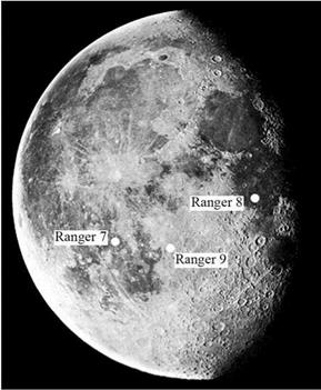
In late September, however, the planners convened to review the target list in the light of the results of the first mission. One factor that influenced Apollo planning was Ranger 7’s pictures of bright rays from Copernicus and Tycho crossing Mare Nubium. If (as was suspected) all rays were highly cratered, then this would argue against such areas being considered as landing sites. To test this hypothesis, Lunar Orbiter 1 had imaged a faint ray crossing Mare Tranquillitatis that originated from Theophilus, a prominent crater in the highlands to the south. There was no H frame coverage to confirm it, but the M frame suggested that the cratering was insufficient to rule out this site (I-P-3) as a potential Apollo site. It was decided to revise the ‘B’ mission to further study this issue by inspecting rays crossing Oceanus Procellarum between the craters Copernicus and Kepler. On 29 September the Surveyor/Orbiter Utilisation Committee, having reviewed the crater densities and slopes derived from Lunar Orbiter 1’s M frames, recommended that eight areas be carried over to Lunar Orbiter 2 for study at higher resolution. Apart from the deletion of the high-perilune photography of the eastern limb, in purely operational terms the ‘B’ mission was to be a repeat of its predecessor.

After serving as the backup for the first mission, Lunar Orbiter 2 had been stored. Once modified, it was mated with its launch vehicle on 31 October and a countdown test that concluded on 3 November certified it ready for flight.

Lunar Orbiter 2 was launched at 23:21 GMT on 6 November 1966. After coasting in parking orbit for 14 minutes, the Agena performed the translunar injection burn. Parts of the spacecraft’s surface had been painted black to reduce the opportunity for reflected sunlight to dazzle the Canopus sensor, and at 08:21 on 7 November this locked on without incident. At 19:30 on 8 November the spacecraft fired its engine for 18 seconds for a 21-m/s midcourse manoeuvre. The modified paint on the base of the vehicle eliminated the thermal problem that had marred the first mission. The 612-second, 830-m/s burn at 20:26 on 10 November put the spacecraft into an initial orbit of 196 x 1,871 km that was inclined at 12.2 degrees to the lunar equator and had a period of 3 hours 38 minutes. At 22:58 on 15 November a 17.4-second 28-m/s burn lowered the perilune to 50 km. The photography began on 18 November. The phase of the Moon was ‘new’ on 12 November; ‘first quarter’ would occur on 20 November and ‘full’ on 28 November.

Several modifications had been made to the photographic system. In particular, an integrating circuit had been added to the focal-plane shutter control logic to ensure that an output signal was not an electrical transient but a genuine command pulse; and a filter had been added to the 20-volt power line in order to minimise electromagnetic interference and spurious triggering of the circuits. An early check showed that the V/H sensor was operating correctly. As the spacecraft’s perilune migrated west with the terminator, on 20 November it photographed site II-P-5 in Mare Tranquillitatis in search of Ranger 8’s impact point. On the next revolution it

image123

The Apollo zone annotated with the primary photographic targets assigned to the Lunar Orbiter 2 mission.


Подпись: Reconnaissance flights 22

inspected the nearby I-P-3 target that had been rated highly on the basis of Lunar Orbiter 1’sM frames, thereby obtaining the H frames which would be required for a more detailed evaluation.

The most striking image of any mission to date was taken on 24 November as one of the maintenance exposures. Douglas Lloyd of Bellcomm had suggested early in planning that at this point the opportunity should be taken to obtain an oblique view of Copernicus, and this had been agreed as II-S-12. The vehicle was at an altitude of 46 km, and the 100-km-diameter crater was some 240 km away to the north of the ground track. The illumination was ideal for discerning the nature of the local topography – on the horizon beyond the crater was a section of the Carpathian Mountains, whose peaks stand 1,000 metres above the surrounding terrain. This was the first view to present the Moon as it would be seen by an astronaut in low orbit. When the picture was issued to the press, the New York Times journalist Walter Sullivan described it as “one of the greatest pictures of the century”.

Another such maintenance exposure, II-S-15, was an oblique of the Marius Hills in the western portion of Oceanus Procellarum, which gave the impression of being volcanic domes.

The photography concluded on 25 November, after all 30 of the specified targets had been documented. The high-gain transmitter failed on 6 December, one day before the readout was to end. Although this resulted in the loss of three M and two H frames of target II-S-1 in the eastern part of Mare Tranquillitatis, these had been taken at the start of the mission and their loss was not serious because some of them had been read out as part of the verification process as the film was running forward. The mission provided a number of high-quality pictures of the far-side. As regards the rays crossing the maria, while the results showed these were not always heavily cratered, II-S-11 located between Copernicus and Kepler was certainly ruled out for Apollo. The micrometeoroid experiment reported three hits. As the first mission had reported no hits, it was speculated that Lunar Orbiter 2 had been exposed to the annual Leonid meteor shower.

On 8 December Lunar Orbiter 2 fired its engine for 62 seconds to increase the inclination of its orbit to 17.5 degrees in order to improve the selenodesy coverage. A 3-second burn on 14 April 1967 reduced the period of the orbit by 65 seconds in order to minimise the time the vehicle would spend in darkness as the Moon passed through the Earth’s shadow on 24 April. After providing almost a year’s worth of selenodesy, on 11 October 1967 Lunar Orbiter 2 was deliberately crashed on the far – side.

The mission provided 184 frames of the 13 primary targets. The screening team reconvened at Langley on 5 December 1966 to assess the results. After the M frames had been examined to identify the terrain units in terms of the regional geology, the H frames were used to make a detailed characterisation in terms of crater densities, slope frequency distributions, blockiness etc.

When the Apollo Site Selection Board convened on 15 December, it was able to discuss the pictures from the first two Lunar Orbiter missions. Shallow pits (‘dimple craters’) on Ranger pictures had been interpreted by some people as having formed by loose material draining into subterranean cavities, with chains of pits indicating

image124

A portion of the picture taken by Lunar Orbiter 2 on 24 November 1966 showing the central peak complex and terraced wall of Copernicus, with a mountain range beyond. This unprecedented oblique view was described as “one of the greatest pictures of the century’’.


Подпись: Reconnaissance flights 223

image125

Подпись: 224 The Apollo zone

An oblique view taken by Lunar Orbiter 2 on 25 November 1966 showing the hills and flow fronts in western Oceanus Procellarum near the crater Marius.

Table 11.2 – Lunar Orbiter 2 orbital manoeuvres and photography

Date

Event/Site

Frames

10 November 15 November

Orbit insertion Perilune cut to 50 km

18 November

II-P-1

16

(5-20)

18 November

II-S-1

4

(21-24)

18 November

II-S-2a

4

(25-28)

18 November

II-S-2b

4

(29-32)

19 November

II-S-3

1

(33)

19 November

II-S-4

1

(34)

19 November

II-P-2

8

(35-42)

19 November

II-P-3a

8

(43-50)

19 November

II-P-3b

8

(51-58)

19 November

II-P-4

8

(59-66)

20 November

II-P-5

8

(67-74)

20 November

II-S-5

1

(75)

20 November

II-P-6a

8

(76-83)

20 November

II-P-6b

8

(84-91)

21 November

II-S-6

1

(92)

21 November

II-S-7

1

(93)

21 November

II-S-8

1

(94)

21 November

II-S-9

1

(95)

22 November

II-P-7a

8

(96-103)

22 November

II-P-7b

8

(104-111)

22 November

II-S-10

1

(112)

22 November

II-P-8a

8

(113-120)

22 November

II-P-8b

8

(121-128)

22 November

II-P-8c

8

(129-1З6)

23 November

II-S-11

1

(137)

23 November

II-P-9

8

(138-145)

23 November

II-P-10a

8

(146-153)

23 November

II-P-10b

8

(154-161)

24 November

II-S-12

1

(162)

24 November

II-P-11a

8

(163-170)

24 November

II-P-11b

8

(171-178)

24 November

II-P-12a

8

(179-186)

24 November

II-P-12b

8

(187-194)

25 November

II-S-13

1

(195)

25 November

II-S-14

1

(196)

25 November

II-P-13a

8

(197-204)

25 November

II-P-13b

8

(205-212)

25 November

II-S-15

1

(213)

25 November

II-S-16

1

(214)

25 November

26 November 6 December

II-S-17

Cut Bimat and start full readout Readout halted

1

(215)

fractures. There was concern that if the maria were lava flows, then by terrestrial analogy they might contain lava tubes which could collapse under the weight of an Apollo lander. Lawrence Rowan of the US Geological Survey ventured that in this respect younger-looking mare areas (such as II-P-2) appeared to pose a greater risk than older-looking mare areas (such as II-P-6). It had been possible to fit 23 Apollo target ellipses into clear-looking patches in the Lunar Orbiter pictures to date. After these had been screened by counting small craters and measuring slopes, eight were selected for further study.

On 5 January 1967 the Surveyor/Orbiter Utilisation Committee approved the plan for the third mission. As its predecessors had reconnoitred all the assigned targets, Lunar Orbiter 3 was to provide additional data for those which the screening process had deemed to be the most promising. The spacecraft was identical, but the operational plan was more sophisticated. At the western end of the Apollo zone, launches at different times of year favoured passing either north or south of the equator. In the case of the first mission, the orbit was inclined at 12 degrees to the lunar equator in order to photograph sites lying south of the equator from a vertical perspective, and for the second mission the orbit was inclined the other way for sites north of the equator. To enable Lunar Orbiter 3 to cover the entire latitude range, its orbit was to be inclined at an angle of 21 degrees. It was given 12 primary and 32 secondary targets. It was to obtain H frames of the best-looking areas that had been imaged by Lunar Orbiter 1 as M frames but not by Lunar Orbiter 2 as H frames. In particular, it was to provide pictures to facilitate stereoscopic analysis to compile terrain maps with 3-metre contours, in order to chart the topography on the line of approach from the east over which an Apollo lander would pass during its powered descent to a target.[32] This marked a switch from reconnoitring areas to certifying specific targets. Some of the secondary frames were oblique views of Apollo sites, taken looking west to show them as they would appear to astronauts preparing to make a descent. It was felt that three Lunar Orbiter missions in the equatorial zone should be sufficient to select targets for the first few Apollo landings. The Manned Spacecraft Center also wanted further radio tracking in lunar orbit to investigate anomalous gravitational effects which had been revealed by tracking the first two missions.

Lunar Orbiter 3 was launched at 01:17:01 GMT on 5 February 1967. Translunar injection was at 01:36:56. The spacecraft was released at 01:39:40 and deployed its appendages. Some 7 hours into the flight, it locked onto Canopus to adopt its cruise attitude. At 15:00 on 6 February the spacecraft executed a 4.3-second, 5.1-m/s midcourse manoeuvre to achieve the orbit insertion point for the desired inclination. At 04:20 on 7 February, an optional refinement was deleted. At 21:54:19 on 8 February the spacecraft began the 542-second burn to enter an initial orbit of

image126

The Apollo zone annotated with the primary photographic targets assigned to the Lunar Orbiter 3 mission.


Подпись: Reconnaissance flights 227

210 x 1,850 km inclined at 21 degrees to the lunar equator with a period of 3 hours 25 minutes. As Lunar Orbiter 2 was still providing selenodesy data, the Deep Space Network tracked both spacecraft to enable the Manned Space Flight Network to obtain experience of simultaneously monitoring two vehicles in lunar orbit, as it would for an Apollo mission.

At 18:13:26 on 12 February, Lunar Orbiter 3 lowered its perilune to 55 km. The photographic mission started on 15 February – the first sequence was of the Apollo target in eastern Tranquillitatis. The phase of the Moon was ‘new’ on 9 February; ‘first quarter’ would occur on 17 February and ‘full’ on 24 February.

When the mechanism that advanced the film started to behave erratically, it was decided to cancel an oblique picture of Grimaldi (III-S-32) in order to start the read out process a day early. Accordingly, at 06:36 GMT on 23 February the spacecraft was told to cut the Bimat strip. But film transport continued to be problematic, and when the motor burned out on 4 March only 182 of the 211 frame-pairs had been transmitted; some of the earliest were lost.3

On 12 April the orbit was revised to minimise the time the spacecraft would spend in darkness during the lunar eclipse of 24 April. On 30 August it made a 125-second burn to circularise its orbit at 160 km, in order to provide experience for the Manned Space Flight Network in tracking a spacecraft in an orbit similar to that which would be used by Apollo. On 9 October 1967 Lunar Orbiter 3 was deliberately crashed on the far-side – two days before its predecessor was commanded to do likewise.

The photographs of III-P-12 were to locate Surveyor 1, and were accumulated in four overlapping blocks on successive revolutions. The lander had oriented its two mast-mounted panels to maximise its shadow and hence improve its visibility on the surface. After it was pin-pointed on an H frame, it was able to be located on one of

Table 11.3 – Lunar Orbiter 3 orbital manoeuvres and photography

Date

Event/Site

Frames

8 February

Orbit insertion

12 February

Perilune cut to 55 km

15 February

III-P-1

16

(5-20)

15 February

III-S-1

4

(21-24)

15 February

III-P-2a

8

(25-32)

15 February

III-P-2b

4

(33-36)

15 February

III-S-2

1

(37)

15 February

III-S-3

1

(38)

16 February

III-S-4

1

(39)

16 February

III-P-3

4

(40-43)

16 February

III-P-4

8

(44-51)

16 February

III-P-5a

8

(52-59)

3 The lost frames

degraded the coverage of III-P-3, III-]

P-4, III-P-

5 and III-P-6.

Table 11.3 cont.

Date

Event/Site

Frames

16 February

III-P-5b

8

(60-67)

16 February

III-P-6

4

(68-71)

17 February

III-S-5

1

(72)

17 February

III-S-6

1

(73)

17 February

III-S-7

4

(74-77)

17 February

III-S-8

1

(78)

17 February

III-S-9

1

(79)

17 February

III-S-10

4

(80-83)

18 February

III-S-11

1

(84)

18 February

III-S-13

1

(85)

18 February

III-P-7a

8

(86-93)

18 February

III-P-7b

8

(94-101)

18 February

III-S-14

1

(102)

18 February

III-S-15

4

(103-106)

19 February

III-S-16

1

(107)

19 February

III-S-17

4

(108-111)

19 February

III-S-18

4

(112-115)

19 February

III-S-19

4

(116-119)

19 February

III-S-21

1

(120)

19 February

III-S-21.5

1

(121)

19 February

III-S-22

1

(122)

20 February

III-S-20

1

(123)

20 February

III-P-8

8

(124-131)

20 February

III-S-23

4

(132-135)

20 February

III-S-24

1

(136)

20 February

III-P-9a

8

(137-144)

20 February

III-P-9b

8

(145-152)

20 February

III-P-9c

8

(153-160)

21 February

III-S-25

1

(161)

21 February

III-S-26

1

(162)

21 February

III-P-10

8

(163-170)

21 February

III-S-27

1

(171)

21 February

III-S-28

1

(172)

21 February

III-P-11

8

(173-180)

22 February

III-P-12b.2

4

(181-184)

22 February

III-P-12a

16

(185-200)

22 February

III-P-12b.1

4

(201-204)

22 February

III-P-12c

8

(205-212)

22 February

III-S-29

1

(213)

22 February

III-S-30

1

(214)

23 February 23 February 4 March

III-S-31

Cut Bimat and start full readout Readout interrupted

1

(215)

image127

Hyginus Rille by Lunar Orbiter 3.

Table 11.4 –

Apollo site reconnaissance

Mission

No. sites

No. exposures

LO-1

9

136

LO-2

13

184

LO-3

18

162

Total

40

482

Note: Some sites were assigned to more than one mission.

the M frames taken by Lunar Orbiter 1 – although only in hindsight. The scientific targets included oblique perspectives of the 32-km-diameter crater Kepler (III-S-26) in Oceanus Procellarum and the 11-km-diameter crater Hyginus in Sinus Medii and the associated rille (III-S-6) that was suspected by some people of being of volcanic origin and was under consideration as a site for an advanced Apollo mission.

As soon as the Lunar Orbiter 3 readout ended, the screening team reconvened at Langley to assess the results. Now that the Surveyor 1 site was known, the landscape observed by that vehicle provided the ‘ground truth’ needed to test the validity of the process of interpreting overhead pictures – this was a major part of the rationale for devoting so many frames to seeking the lander.

As a result of the first three Lunar Orbiter missions 32 individual sites clustered in eleven groups in the Apollo zone had been comprehensively photographed. These, and nine less intensively imaged sites, were designated ‘Set A’ for the selection of the early Apollo landings sites.

Herodolui,


II-P-4


II-P-5


ПИ>,7


II-P-9


Щ-Р-з


HIPPARCHUS


ЦтЕ=і2


I-P-9.2


^Copello


I-P-8.1


III-P-8


AI^A^GNIL


image128

The Apollo zone

assail

FPACASTORIL

PU P’BsAC I

PEGIOMGN1

■ РІТАТЦЗ.

Подпись: Reconnaissance flights 23The Apollo zone annotated with the primary photographic targets jointly assigned to the Lunar Orbiter 1, 2 and 3 missions.

Подпись: 232 The Apollo zone

Г 2300

Taruntius Е
(1600)


Taruntius ЕА


4SKELYME F


Wk 2200

У Taruntius F

(1500)


MASKELYNE D


Maskelynefc


LUBBOCK s


‘iooo 1 CENSORINUS

(380) 4


UfKELYNE A

12000)


1060»


^ensorinus U’


2850′

:ensorini


image129

image130

‘1000 1 CENSORINUS

(380) 4

:ensorinus n 1

Подпись: 234 The Apollo zone

Г 2300

Taruntius Е
(1600)


Taruntius ЕА


4SKELYME F


Wk 2200

S Taruntius F

(1500)


MASKELYNE D


Maskelynefc


LUBBOCK s


LUBBOCK P


UgKELYNE A

J12000)


1060»


^ensorinus U’


image131

image132

Подпись: 236 The Apollo zone

f 2300
Toruntius E
(1600)


larunlius EA


(f 2200

Taruntius F
(1500)


MASKELYNE D


Moskelynefc


LUBBOCK S


LUBBOCK P


-1000 1

:ensorinus

(380) 4


The Apollo zone

1060»


Й’ф Vtv*

2850′

:ensorini


image133

image134

Подпись: 238 The Apollo zone

Г 2300

Taruntius Е
(1600)


Taruntius ЕА


4SKELYME F


I 2200

Taruntius F
(1500)


MASKELYNE


Maskelynefc


LUBBOCK S


lubbock p


-1000 1

:ensorinus

(380) 4


UgKELYNE A

12000)


1060»


^ensorinus U’


г 2850′

iCENSORINI


image135

image136

‘1000 1

CENSORINUS

(380) 4

Подпись: 240 The Apollo zone

f 2300
Toruntius E
(1600)


larunlius EA


^SKELYNE F


I 2200

Taruntius F
(1500)


MASKELYNE D


Moskelynefc


LUBBOCK S ■


LUBBOCK P


UgKELYNE A

. , J J2000)


1060»


1::


2850′

:ensorini


Ceniorinus


image137

image138

Подпись: Lunar Orbiter photographic target III-P-2.
image139

242 The Apollo zone

image140

Подпись: 244 The Apollo zone

Arogo В


^ARAGO

1 (1800)


4700

MANNERS

W1800) .


LAMONT


Manners A


Ritter В (2000)


Maskelyne К


1900

MASKELYNE.

(2500^f£


Maskelyne G


RITTER

(1300)


Maskelyne

(1900)


У/ 4300‘

V SABINE


) SCHMIDT
(1600)


m MOLTKE’

§)"07X’


image141

image142

Подпись: 246 The Apollo zone

>ARAGO

• (1800)


LAMONT


Manners A


Ritter В (2000)


Maskel/ne К


1900

MASKELYNE,

(2500Ы^Й


RITTER

(1300)


Maskelyne В
(1900)


) SCHMIDT
(1600)


moltke’


image143

image144

Подпись: 248 The Apollo zone

>ARAGO

• (1800)


4700

MANNERS

-<(>800) ,


LAMONT


Manners A


Ritter В (2000)


Moskelyne К


1900

MASKELYNE,

(2500^g£


RITTER

(7300)


Moskelyne В
(1900)


) SCHMIDT
(1600)


moltke’


image145

image146

Подпись: 250 The Apollo zone

V


4300

>ARAGO

• (1800)


4700

MANNERS

-<(>800) ,


LAMONT


Manners A


Ritter В (2000)


Moskel/ne К


1900

MASKELYNE,

(2500Ы^


RITTER

(7300)


Maskelyne В
(1900)


) SCHMIDT
(1600)


. moltke’

§)no;^


image147

image148

Подпись: 252 The Apollo zone

UADAEUS E


Iberschlag


4700

MANNERS

v(l 800) ,


– Ariadaeus В
(1500)


ARIADAEUS
6)4 00)


Manners A


WHEWELL (7, (2200) і


AGRIPPA

J3*0)^s’


TEMPEL


CAYLEY

(2500)


De


Ritter В (2000)


D’ARREST )


RITTER

(1300)


9100


1/OOf


JSCHMIDT

(1600)


Theon Senior A


"Hypatia E„


(J690)


image149

image150

Подпись: 254 The Apollo zone

UADAEUS E


Iberschlag


4700

MANNERS

v(l 800) ,


– Ariadaeus В
(1500)


IRIADAEUS I V 400)


Manners A


WHEWELL (7, (2200) і


AGRIPPA

J3W)^s’


^5200 ‘ CAYLEY (2500)


TEMPEL


Ritter В (2000)


D’ARREST )


RITTER

(1300)


JSCHMIDT

(1600)


Theon Senior A


8500 I Lade M (J690)


(3°25|


image151

image152

Подпись: Lunar Orbiter photographic target I-P-5.
image153

256 The Apollo zone

image154

mm


Подпись: 258 The Apollo zone

SCHROTER


j; 5400′ BRUCE (800)


SO/v^MERING M


630R


RHAETICUS L


J240R


Reaumur


Mosting


U3000)-


О P P О L Z E R"


. ГГ.


J 5800 SEELIGER (1070)


FLAMMARI^


400RI1

SPORER


jjvi


image155

image156

• ‘ I4

шш

жде


Подпись: 260 The Apollo zone

SCHROTER


5400′

BRUCE

(800)


SO/v^MERING M


630R


RHAETICUS L


Ї 240R


Reaumur


Mosting


О P P О L Z E R’


[(3000) ■


J 5800 SEELIGER (1070)


«I


FLAMMARI^


400RI1

SPORER


image157

Lunar Orbiter photographic target II-P-8.

37004-

7AMBAR1

(1090)

Lunar Orbiter photographic target I-P-7.

Lunar Orbiter photographic target II-P-11.

І uWl

By design, the ellipses selected as potential targets for the first Apollo landing were bland areas.

Apollo site short-list 285

A SPECTACULAR ‘ALL UP’ TEST

The 1966 schedule had called for the first Saturn V launch early in 1967 but few people believed that this would be feasible owing to problems with the S-II, which had become the ‘pacing item’. In fact, the delivery of the first ‘live’ S-II to the Cape had already slipped from July to October 1966, and on its arrival at the Mississippi Test Facility on 13 August the inspectors found a number of cracks which delayed the start of its acceptance test firings. In November 1966 Sam Phillips revised the schedule to require the S-II for AS-501 to arrive at the Cape on 9 January 1967 for launch in April.

Meanwhile, the S-IC stage had been erected upon a mobile launch platform in the VAB on 27 October. So as not to delay the checkout of the vehicle, a bobbin-shaped ‘spacer’ was stacked in place of the S-II to support the S-IVB, and on 12 January 1967 the spacecraft comprising CSM-017 and LTA-10R in the SLA was added for its own checkout.

When the S-II arrived on 21 January 1967, several faults were found. By now the launch had slipped into May. On 14 February the spacecraft was transferred to the Operations and Checkout Building for examination as part of the investigation of the Apollo 1 fire, and so many wiring discrepancies were identified that repairs ran into June. In the meantime the S-IVB was de-mated, and on 23 February the spacer was replaced by the S-II. But when factory inspectors discovered cracks in another S – II being prepared for shipment, the S-II was destacked on 24 May for inspection and not restacked until mid-June. Once the S-IVB had been added, the revised spacecraft was installed on 20 June. CSM-017 was a Block I with some Block II modifications for certification, including a heat shield with a simulated unified crew hatch and the

CSM-101 was to fly the Saturn IB and manned CSM evaluation, and CSM-102 was to be retained by North American Aviation as a ground test article.

AS-501 is transported to Pad 39A in readiness for the Apollo 4 mission.

As Apollo 4 soars into the sky it is trailed by a 1,000-foot long plume.

umbilical which crossed the rim of the basal shield from the command module to the service module. The crawler transported AS-501 to Pad 39A on 26 August. The plan was to start the 6-day countdown demonstration test on 20 September but it slipped to 27 September and a variety of issues delayed its completion to 13 October. To be fair, however, this was the first Saturn V, it was vastly more complex than any other space vehicle, and the launch operations team was on a learning curve.

The countdown for Apollo 4 began on 6 November, ran smoothly, and the vehicle lifted off on time at 12:00:01 GMT on 9 November 1967.

For the crowds, the first indication that a launch was in progress was a light at the base of the vehicle. A jet of flame passed through a hole in the launch platform to a wedge-shaped deflector, which split and vented it horizontally north and south. The water which was pumped onto the pad to diminish the acoustic reflection from the concrete was vaporised and blasted out with the flame as a roiling white cloud. It was almost inconceivable that a vehicle that weighed 6.5 million pounds could rise from the ground, but the five F-1 engines generated a total of 7.5 million pounds of thrust and as it slowly lifted from the pad the brilliance of the flame rivalled the early morning Sun. Since the Saturn V was so much more powerful than its predecessors, nobody really knew what to expect. At first it was like a silent movie, because the thunderous roar of ignition took fully 15 seconds to reach the facilities for the public and press, which were 3.5 miles from the pad because this had been computed to be as far as an exploding vehicle could hurl a 100-pound fragment. Deafening as this roar was, as the vehicle rose it was enhanced by a staccato pop and crackle that was more felt than heard. The ground shook sufficiently to register on remote seismic sensors. The effect not only rattled the tin roof of the VIP bleacher alarmingly but also threatened to collapse the lightweight booth from which Walter Cronkite was providing TV commentary. It was incredible to think that one day soon men would ride such a rocket.

During the first 10 seconds of the ascent the 363-foot-tall vehicle performed a yaw manoeuvre to ‘side step’ away from the launch umbilical tower, in order both to preclude a collision with any swing arm that might be tardy in rotating clear and to resist any wind gusts that might otherwise cause it to drift towards the 400-foot-tall structure. Liftoff was on a pad azimuth of 90°E of N, but once clear of the tower it initiated a roll to align its inertial guidance system with the flight azimuth of 72°E and then it pitched over. It achieved Mach 1 at T + 61.4 seconds. Then at T + 78.4, at an altitude of 37,700 feet and a wind speed of 50 knots, it passed through the region of maximum dynamic pressure. The central engine of the S-IC was shut down by a timer at T+ 135.52, and the outer engines were cut off by liquid oxygen depletion at T+ 150.77. The separation proceeded in two phases. Firstly, at T+ 151.43, the S-IC separated from the interstage, or ‘skirt’, that extended down over the engines of the S-II; then at T+ 152.12 the S-II ignited its five J-2 engines and at T+ 181.44 the skirt was jettisoned. This scheme was designed to ensure that the S-IC could not damage the engines projecting from the base of the S-II as it separated. A small solid rocket motor on the launch escape system fired at T+ 187.13 to draw this structure clear of the spacecraft. The S-II shut down at T+519.76 and was jettisoned at T+520.53. A pair of solid rockets on the periphery of the S-IVB settled the liquid propellants prior to J-2 ignition and were then jettisoned. The vehicle attained a near-circular parking orbit at an altitude of 100 nautical miles, and the continuous-vent system maintained ullage pressure in the propellant tanks during the coast phase. At 003:11:26.6,[49] after essentially two revolutions with its longitudinal axis in the orbital plane and parallel to the local horizon, it reignited for a simulated translunar injection, although in this case the burn of almost 5 minutes was to create an elliptical atmosphere-intersecting ‘waiting orbit’ with an apogee of 9,292 nautical miles.

CSM-017 was released at 003:26:28.2, and at 003:28:06.6 the service propulsion system was briefly fired to demonstrate its ability to ignite in the zero-g environment without an ullage impulse to settle its propellants. This burn had the effect of raising the apogee to 9,769 nautical miles. The vehicle then aligned itself with its main axis perpendicular to the Sun and its hatch on the sunny side. It maintained this attitude for about 4.5 hours to induce circumferential thermal stresses and distortions on the command module and its ablator prior to entry. At 005:46:49.5 the vehicle attained its high apogee. During this coast, an automated 70-mm camera took a total of 715 high-resolution pictures of Earth at 10.6-second intervals. At 008:10:54.8 the service propulsion system was reignited to accelerate and set up an atmospheric entry which would subject the heat shield to the most severe operational conditions that a return from the Moon might impose. An inertial velocity of 34,816 ft/sec was intended, but a slight over-burn owing to the manoeuvre being controlled from the ground yielded 35,115 ft/sec.

The command module separated 2 minutes 27 seconds later, and used its thrusters to adopt entry attitude. The entry interface (an altitude 400,000 feet, by definition) occurred at 008:29:28.5 while travelling at an inertial velocity of 36,639 ft/sec and a flight path angle of-6.93 degrees. As a result of the longer than planned final burn of the service propulsion system the conditions at the entry interface were 210 ft/sec faster than nominal and the flight path angle 0.20 degrees shallower, yet still within the desired ‘corridor’. Due to the change in the entry conditions, the dynamic load of 7.27 g was less than the predicted 8.3 g. This did not affect the performance of the guidance system in achieving the target, however. The lift-to-drag ratio was 0.365 ( + 0.015) compared with the predicted 0.350. The command module splashed into the Pacific 10 nautical miles from the aim point at 008:37:09.2, and was soon recovered by USS Bennington.

With the spectacular success of this ‘all up’ demonstration flight, there was a real prospect of achieving Kennedy’s challenge of landing a man on the Moon before the decade was out. Indeed, on 20 November 1967 NASA publicly revealed that James McDivitt, David Scott and Rusty Schweickart, who had been trained to fly the dual launch version of the ‘D’ mission using the Saturn IB, were to be launched on the first manned Saturn V. They were to be backed up by Pete Conrad, Dick Gordon and Al Bean – the latter replacing Clifton Williams, who was killed in an air accident on 5 October 1967. Frank Borman, Michael Collins and Bill Anders, backed up by

Neil Armstrong, James Lovell and Buzz Aldrin, would still perform the high-apogee ‘E’ mission, but would ride the second manned Saturn V. If the lunar orbit ‘F’ mission were deleted, then the next crew would attempt a lunar landing.

WHENCE THE MOON?

A number of theories have been suggested over the years to explain the origin of the Moon, which is unique as a planetary satellite in that it has the greatest mass as a fraction of its primary, with the result that its orbital angular momentum exceeds the rotational momentum of the planet.

Whence the Moon? 31

In 1796 the French mathematician Pierre Simon de Laplace, inspired by the rings of Saturn, proposed that the solar system formed by the gravitational collapse of an enormous cloud of gas which was in a state of rotation. The conservation of angular momentum would have required the rate of rotation to increase, causing material to be shed every so often and making a series of concentric rings in a single plane. The central mass eventually formed the Sun, which was sufficiently hot to become self­luminous. As each ring of material condensed to become a planet, the process would have shed local rings which in turn formed satellites – in Earth’s case, the Moon. In Laplace’s time, the solar system appeared to comprise the entire celestial realm apart from the stars, and therefore his nebular hypothesis was the first serious attempt at cosmogony. Although accepted for many years, mathematical analysis later showed that it would not work as Laplace had imagined.

In 1878 George H. Darwin posited that the Earth and Moon formed together. The rapidly rotating body of hot liquid became an ellipsoid, rotating about its minor axis in an unstable equilibrium with two forces acting upon it: its own natural period of vibration, and tides raised by the Sun’s gravity. Once the forces achieved resonance, the shape became progressively more like a dumbbell until one day the narrow ‘neck’ collapsed, leaving two masses, the larger becoming Earth and the smaller the Moon. This fission hypothesis was popular for some time, but was later discarded owing to mathematical deficiencies, not least because a rapidly spinning ball of fluid would tend to divide into two more or less comparable masses, whereas the Moon has only 1/81st the mass of Earth.

In The Planets: Their Origin and Development, which was based on lectures he gave at Yale University and published in 1952, Harold Urey discussed the Moon in relation to the solar system as a whole. He argued that the Moon condensed from the solar nebula independently, and was later captured by Earth. Furthermore, he said it had never undergone thermal differentiation and that, consequently, its surface had no volcanic structures. This was dubbed the ‘cold Moon’ hypothesis.

In 1954 Gerard Kuiper proposed that the Earth and Moon formed simulta­neously in a common envelope within the solar nebula, and soon became gravitationally bound. He said the preponderance of craters was due to the Moon sweeping up all the debris in the neighbourhood. As the Moon’s mass is relatively large as a ratio of its primary, this made the Earth and its Moon essentially a ‘double planet’.

Nevertheless, as the space age dawned the origin of the Moon and the state of its interior were contested.

LOBOTOMY

Ranger 4 arrived at the Cape on 26 February 1962. The countdown ran smoothly to liftoff at 20:50 GMT on 23 April. The Atlas performed satisfactorily, the Agena achieved the desired parking orbit and then made the translunar injection manoeuvre as planned. But when the spacecraft appeared above the horizon at Johannesburg it was transmitting a carrier signal without encoded telemetry, which meant that it was not possible to determine the state of the systems. Unable to lock onto the Sun, the initial instabilities imparted by separation from the spent stage caused the spacecraft to tumble. It was concluded that the master clock in the computer/sequencer must have failed. Ranger 4 had transmitted telemetry during the ascent, but the clock had stopped at some point in the gap in coverage between the vehicle passing beyond the final station of the Eastern Test Range and its coming into range of Johannesburg. In effect, the Agena had released a lobotomised robot. Ironically, the radar tracking by Woomera showed that the slight discrepancy in the trajectory would have been well within the capacity of the spacecraft to correct.

The target for Ranger 4 was the same as for its predecessor. The Moon was ‘full’ on 20 April and would be ‘last quarter’ on 27 April. James Webb, W. H. Pickering, Oran Nicks, Clifford Cummings and James Burke congregated at Goldstone on 26 April as the spacecraft approached the Moon. Without solar power, the battery had expired, terminating the carrier wave from the main transmitter, but the fact that the independently powered surface package was transmitting enabled radio tracking to continue. At 12:47 GMT, some 64 hours after launch, the spacecraft passed behind the leading limb of the Moon. Calculations showed that it impacted 2 minutes later.

For the first time, American hardware had hit the Moon, marking a success for

image44

On 23 April 1962 an Atlas-Agena lifts off with the Ranger 4 spacecraft.

the launch vehicle – but this was little consolation for the spacecraft engineers, and the scientists gained nothing. On the one hand, in the original concept of the Block II it was deemed that three flights would be necessary to have a reasonable probability of achieving a fully successful flight that would deliver the scientific objectives of the project. However, the scientists appeared to think that every flight should succeed! It was difficult to precisely determine why Ranger 4’s clock had stopped, because the failure occurred when out of communication and it prevented the transmission of telemetry. But because the telemetry was present when the spacecraft was last seen on the Agena and absent following its release, attention focused on the separation procedure – in particular, when the umbilical plug was withdrawn from the bus and the onboard computer/sequencer issued the power-up command to the systems. It was inferred that there must have been a short circuit at this time, and the obvious root cause was the heat sterilisation process. Additional waivers were issued, but the computer/sequencer for Ranger 5 had already been treated. With mass no longer an issue for the Block II, it was decided to install a backup clock in order to ensure that telemetry would be produced in the event of the computer/sequencer being disabled.

APOLLO SITE SHORT-LIST

When the Apollo Site Selection Board met on 30 March 1967 the Apollo officials announced that whilst they would seek further Lunar Orbiter data, that from the first three missions satisfied “the minimal requirements of the Apollo program for site survey for the first Apollo landing”. By now nine mare sites in the Apollo zone were deemed to be suitable as ‘prime sites’ for the early Apollo landings: one in Mare Foecunditatis, two in Mare Tranquillitatis, one in Sinus Medii and five in Oceanus Procellarum. These were designated ‘Set B’.4 For each such site, the US Geological Survey produced geological maps at scales of 1:25,000 and 1:100,000 to supplement the 1:1,000,000 regional maps. It was noticed that the sites on the eastern maria had high densities of large but shallow craters, and the sites on the western maria were generally flatter but rougher in detail. The astronomers had long ago noted that there was a difference in spectral hue, with the eastern maria being bluish and the western maria reddish.

On 15 December 1967 the Apollo Site Selection Board convened at the Manned Spacecraft Center to refine the target list for the first Apollo landing. All of the sites of Set B were acceptable in terms of their approach routes. However, as a landing in Mare Foecunditatis would not allow sufficient time after rounding the eastern limb for radio tracking to verify the lander’s trajectory prior to powered descent, this site was discarded. Five sites were short-listed as ‘Set C’. It was decided that three of these must be selected as options for the first landing mission, forming a prime site and two backups spaced in lunar longitude to accommodate successive 2-day delays in launch. It was recognised that the need for the crew to familiarise themselves with three sites would increase their training burden, but there would be no impact on the surface activities because the first landing was not to include a mapped traverse. In east to west sequence, the five sites were II-P-2, II-P-6, II-P-8, III-P-11 and II-P-13. Whilst it was clear that the prime site would be in the eastern hemisphere, the meeting did not specify whether it should be II-P-2 or II-P-6.

On 26 September 1968 the Set C ellipses were ‘stretched’ from 5.3 x 7.9 km to 5.0 x 15.0 km to allow for uncertainties in the Moon’s gravitational field that might cause a lander to come in either ‘short’ or ‘long’ of the designated aim point. On 3 June 1969 the Set C sites were renamed Apollo Landing Site (ALS) 1 through 5 respectively.

They were I-P-1 in Mare Foecunditatis, II-P-2 and II-P-6 in Mare Tranquillitatis, II-P-8 in Sinus Medii, and II-P-11, III-P-9, III-P-11, III-P-12 and II-P-13 in Oceanus Procellarum.