Category Apollo Saturn V News Reference

FUEL LEVEL SENSING AND ENGINE CUTOFF SYSTEMS

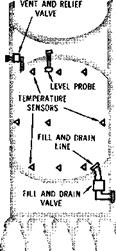
A cutoff sensor mounted on the bottom of the fuel tank provides signal voltages to shut off fuel after a predetermined level of depletion is reached. The fuel is measured during flight by four fuel slosh probes and a single liquid level measuring probe. Fuel levels are detected electronically and reported through the stage telemetry system. Telemetry

2-8
signals are transmitted to ground support either by radio frequency or, before launch, by coaxial cable. The cutoff sensor, mounted in the lower fuel tank bulkhead, initiates engine cutoff as fuel level falls below two sensing points on the probe. Engine cutoff will normally be initiated by sensors in the LOX system. The cutoff capability is provided as a backup system should fuel be depleted before LOX.

image40

Fuel Level Sensing and Engine Cutoff

FUEL PRESSURIZATION SYSTEM

The fuel pressurization system maintains enough pressure in the fuel tank to provide proper suction at the fuel turbopumps to start and operate en­gines. The system consists of a helium supply, a helium flow controller, helium fill and drain com­ponents, a prepressurization subsystem, a fuel tank vent and relief valve, and associated ducts.

Four 31-cubic-foot, high pressure storage bottles in the LOX tank store the helium required for in­flight pressurization of the fuel tank ullage. A high pressure line is used for filling the bottles and rout­ing the helium to the flow controller. A solenoid dump valve is installed for emergencies. The helium flow controller uses five solenoid valves mounted parallel in a manifold to control helium flow to the fuel tank ullage. The cold helium duct routes helium from the flow controller to the cold helium mani­fold. From there, it is distributed to the heat ex­changers on the five F-l engines. The hot helium manifold receives the heated, expanded helium from the engine heat exchangers and routes it to the hot helium duct which then carries it through the he­lium distributor and on to the fuel tank ullage.

image41

SATURN V NEWS REFERENCE

It is replenished between the periods of loading and prepressurization through the fill and drain line.

Before LOX drain can be performed, the helium cylinders in the LOX tank must have their pressure decreased from about 3,100 psig to about 1,660 psig. Fill and drain valves are opened to complete drainage of the LOX tank although total evacua­tion of LOX from the tank requires draining the engines or waiting for boil-off of residual LOX. LOX drain can be speeded with the aid of a pres­surizing gas, usually nitrogen.

Turbine

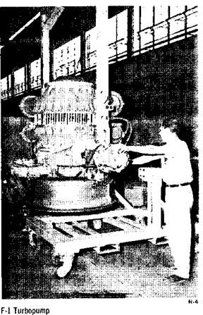
The turbine, producing 55,000 brake horsepower, drives the fuel and oxidizer pumps. It is a two-stage, velocity-compounded turbine consisting of two ro­tating impulse wheels separated by a set of stators. The turbine mounts on the fuel pump end of the turbopump so that the two elements of the turbo­pump having the greatest operating temperature extremes (1500 Fahrenheit for the turbine and -300

Hot gas from the gas generator enters the turbine at a flowrate of 170 pounds per second through the inlet manifold and is directed through the first-stage nozzle onto the 119-blade first-stage wheel. The hot gas then passes through the second-stage stators onto the 107-blade second-stage wheel, and then into the heat exchanger. This flow of hot gas rotates the turbine, which in turn rotates the propellant pumps. Turbine speed during mainstage operation is 5,550 rpm.

Bearing Coolant Control Valve

This valve, which incorporates three 40-micron fil­ters, three spring-loaded poppets, and a restrictor, performs two functions. Its primary function is to control the supply of coolant fuel to the turbopump bearings. Its secondary function is to provide a means of preserving the turbopump bearings be­tween static firings or during engine storage. During engine firing, the coolant poppet opens and delivers filtered fuel to the turbopump bearing coolant jets, and the restrictor provides the proper turbopump bearing jet pressure.

GAS GENERATOR SYSTEM

The gas generator system provides the hot gases for driving the velocity-compounded turbine, which drives the fuel and oxidizer pumps. The system con­sists of a gas generator valve, an injector, a com­bustion chamber, and propellant feed lines connect­ing the No. 2 turbopump fuel and oxidizer outlet lines to the gas generator. The propellants are supplied to the gas generator from the No. 2 turbo­pump fuel and oxidizer outlet lines. The gas genera­tor mixture ratio, relative to the engine mixture ratio, is fuel-rich. This provides a lower combustion temperature in the uncooled gas generator and in the turbine.

Propellants enter the gas generator through the valve and injector and are ignited in the combustion chamber by dual pyrotechnic igniters. The gas generator valve is hydraulically operated by fuel pressure from the hydraulic control system.

Venting Subsystem

The venting subsystem is used during loading and flight operations. While the propellant tanks are being loaded, the vent valves (two for each tank) are opened by electrical signals from ground equipment to allow the gas created by propellant boil-off to leave the tanks. The valves are spring-loaded to be normally closed, but a relief valve will open them if pressure in the tanks reaches an excessive level. Each valve is capable of venting enough gas to

4-8


image87

Подпись: SATURN V NEWS REFERENCE

The LH2 recirculation subsystem pumps the propel­lants through the feed lines and valves and back to the LIL tank through a single return line. The pumps are powered from a 56-volt DC battery sys­tem located in the interstage; the batteries are ejected with the interstage approximately 30 sec­onds after first plane separation. Refore liftoff, power for the LH2 recirculation subsystem is sup­plied by ground equipment.

The LOX recirculation system works on the basis of a thermal syphon; heat entering the system is used to provide pumping action by means of fluid density differences across the system. Helium gas is used to supplement the density differences and thereby improve the pumping action.

Recirculation of oxygen begins at the start of tank­ing; LIL recirculation begins just before launch. The propellants continue to circulate through first stage firing and up until just before the first stage and second stage separate. While the subsystems are operating, the LH2 prevalves which lead to the combustion chambers are closed; as soon as the re­circulation subsystem stops, the LH2 prevalves open and the engines ignite.

Propellant Management System

The propellant management system controls load­ing, flow rates, and measurement of the propel­lants. It includes propellant utilization, propellant loading, propellant mass indication, engine cutoff, and propellant level monitoring subsystems.

PROPELLANT UTILIZATION SUBSYSTEM

The propellant utilization subsystem controls the flow rates of liquid hydrogen and liquid oxygen in such a manner that both will be depleted simulta­neously. It controls the mixture ratio so as to min­imize propellant residuals (propellant left in the tanks) at engine cutoff. Propellant utilization bypass valves at the liquid oxygen turbopump outlets con­trol flow of liquid oxygen in relation to the liquid hydrogen remaining. Control of the engine mixture ratio increases the stage’s payload capability. The propellant utilization subsystem is interrelated with the propellant loading subsystem and uses some of the same tank sensors and ground checkout equip­ment.

PROPELLANT LOADING SUBSYSTEM

The loading subsystem is used to control propellant loading and maintain the quantity of propellants
in the tanks. Capacitance probes (sensors) running the full length of the propellant tanks sense liquid mass in the tanks and send signals to an airborne computer, which relays them to a ground computer to control loading. They also send signals to an airborne computer for the propellant utilization subsystem’s control of flow rates.

PROPELLANT MASS INDICATION SUBSYSTEM

The propellant mass indication subsystem is in­tegrated with the propellant loading subsystem and is used to send signals to the flight telemetry sys­tem for transmission to the ground. It utilizes pro­pellant loading sensors to determine propellant levels.

ENGINE CUTOFF SUBSYSTEM

The main function of the engine cutoff subsystem is to signal the depletion point of either propellant. It is an independent subsystem and consists of five sensors in each propellant tank and associated electronics. The sensors will initiate a signal to shut down the engines when two out of five sensors in the same tank signal that propellant is depleted.

RANGE SAFETY SYSTEM

The range safety system terminates vehicle flight upon command of the range safety officer. Redun­dant systems are used throughout to provide max­imum reliability.

Four antennas, mounted around the periphery of the third stage forward skirt assembly, feed two redundant secure range receivers located in the for­ward skirt assembly. Both receivers have separate power supplies and circuits. A unique combination of coded signals must be transmitted, received, and decoded to energize this destruct system.

A safety and arming device prevents inadvertent initiation of the explosive train by providing a posi­tive isolation of the EBW detonator and explosive train until arming is commanded. Visual and remote indications of SAFE and ARMED conditions are displayed at all times at the firing center. Upon proper command, EBW firing units activate EBW detonators.

A CDF, detonated by the safety and arming device, explodes a flexible linear-shaped charge which cuts through the tank skin to disperse both fuel and oxidizer.

RANGE SAFETY SYSTEM

5-13


I SATURN V NEWS REFERENCE

J-2 ENGINE FACT SHEET

image122

image123

R-16


LENGTH

WIDTH

NOZZLE EXIT DIAMETER THRUST (altitude)

SPECIFIC IMPULSE RATED RUN DURATION FLOWRATE: Oxidizer Fuel

MIXTURE RATIO CHAMBER PRESSURE (Pc)

WEIGHT, DRY, FLIGHT CONFIGURATION

EXPANSION AREA RATIO

COMBUSTION TEMPERATURE

Note: J-2 engines will be uprated to a maximum

11 ft. 1 in.

6 ft. SV2 in.

6 ft. 5 in.

225,0 lb.

424 sec. (427 at 5:1 mixture ratio)

500 sec.

449 lb sec (2,847 gpm)

81.7 lb sec (8,365 gpm)

5.5:1 oxidizer to fuel 763 psia 3,480 lb.

27.5:1

5,750°F

of 230,000 pounds of thrust for later vehicles.

Подпись: chamber throat and the exit at a pressure of more than 1,000 psi. In cooling the chamber the fuel makes a one-half pass downward through 180 tubes and is returned in a full pass up to the thrust chamber injector through 360 tubes. (See schematic drawing.) DOME The injector and oxidizer dome assembly is located at the top of the thrust chamber. The dome provides a manifold for the distribution of the liquid oxygen to the injector and serves as a mount for the gimbal bearing and the augmented spark igniter. THRUST CHAMBER INJECTOR The thrust chamber injector atomizes and mixes the propellants in a manner to produce the most efficient combustion. Six hundred and fourteen hollow' oxidizer posts are machined to form an integral part of the injector. Fuel nozzles are threaded and installed over the oxidizer posts forming concentric orifices. The injector face is porous and is formed from layers of stainless steel wire mesh and is welded at its periphery to the injector body. Each fuel nozzle is swaged to the face of the injector. The injector receives liquid oxygen through the dome manifold and injects it through the oxidizer posts into the combustion area of the thrust chamber. The fuel is received from the upper fuel manifold in the thrust chamber and injected through the fuel orifices which are concentric with the oxidizer orifices. The propellants are injected uniformly to ensure satisfactory combustion. GIMBAL The gimbal is a compact, highly loaded (20,000 psi) universal joint consisting of a spherical, socket- type bearing with a Teflon/fiberglass composition coating that provides a dry, low-friction bearing surface. It also includes a lateral adjustment device for aligning the chamber with the vehicle. The gimbal transmits the thrust from the injector assembly to the vehicle thrust structure and provides a pivot bearing for deflection of the thrust vector, thus providing flight attitude control of the vehicle. The gimbal is mounted on the top of the injector and oxidizer dome assembly. 6-і

I SATURN V NEWS REFERENCE

NORTH AMERICAN ROCKETDYNE FACILITIES

F-l and J-2 engines for the Saturn V launch vehicle are manufactured at Rocketdyne’s main complex in Canoga Park, Calif. F-l static testing is conducted at the Edwards Field Laboratory located at the NASA Rocket Engine Test Site, Edwards, Calif., about 125 miles northeast of Los Angeles, and the J-2 is tested at Rocketdyne’s Santa Susana Field Laboratory located about 10 miles from Canoga Park. Rocketdyne operates the Neosho Facility (Missouri), which produces and tests subcompo­nents of the J-2 and F-l engines.

image161

R-ll

F-l Test Stands—Three of six stands for testing F-l rocket engines or components at full thrust are visible in this aerial view of NASA Rocket Engine Test Site.

image162

R-12

F-l Test Firing… An F-l rocket engine developing 1,500,000

pounds of thrust is tested at NASA Rocket Engine Test Site. The stand is one of six in the complex.

Подпись: 8 5

Manufacturing of components and final assembly of both engines are carried out in eight buildings in

Подпись: SATURN V NEWS REFERENCE

the Canoga complex. These facilities are equipped with general purpose machine tools for precision and heavy machining as well as some 20 numerically controlled machines for performing programmed multiple machining operations. Also included are two of the largest gas-fired brazing furnaces of their type for brazing of thrust chamber tubes and in­jectors, eight units for ultrasonic cleaning, 21 in­stallations for Gamma and X-ray inspection, more than 50 environmentally controlled areas for ultra­clean assembly operations, sheet metal prepara­tion, precision cleaning, and receiving inspection.

image164

R-13

F-l Flight Engine Firing

An Engineering Development Laboratory pro­vides specialized facilities to support manufacturing programs. These facilities include a high-flow water test facility for checking propellant systems, 12 concrete cells for conducting hazardous tests, 28 environmental test chambers, a photo-elastic lab­oratory, two pneumatic flow benches, six vibration test rooms, and others for checking components as well as complete engines.

Research and development testing of F-l turbo­machinery, gas generators, heat-exchangers, seals, and splines is conducted on two test stands and three components test laboratories at Santa Susana.

Six large test stands, with a total of eight test posi­tions, and associated shops and support facilities at the Edwards Field Laboratory are used for testing complete F-l engines as well as injectors.

Six large engine test stand positions at the Santa Susana Field Laboratory are used for testing the J-2. One of these stands is equipped with a steam injection diffuser for altitude simulation testing. J-2 turbopumps, gas generators, valves seals, bear­ings, and other components are tested in 22 test cells in five component test laboratories in Santa Susana.

image165

R-14

Pump Tests-Flames from gases burned during test of an F-l engine turbopump shoot more than 150 feet in air.

image166

R-15

J-2 Testing—A hydrogen fueled J-2 rocket engine is tested under ambient altitude conditions at Santa Susana.

8-6


SATURN V NEWS REFERENCE


LOX DELIVERY SYSTEM

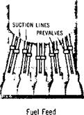
LOX is delivered to the engines by five 17-inch suction lines which pass through the fuel tank in five LOX tunnels. LOX suction ducts make up the lines from the LOX tank to the prevalves in the thrust structure. The ducts are equipped with gim­bals and sliding joints to counteract vibration and swelling or contraction caused by temperature. In­side the tunnels, air acts as the insulation between the LOX-wetted lines and the fuel-wetted tunnels.

image42

LOX Delivery

LOX level engine cutoff sensors in the suction lines assure safe engine shutdown and leave a minimum amount of unused LOX in the system.

In case of emergency, LOX prevalves in each suc­tion line can stop the flow of LOX to the engines.

LOX CONDITIONING SYSTEM
it will result in gaseous oxygen (GOX). If heat is increased, the result is boiling and not temperature increase since evaporation is a cooling process. Depth in a body of LOX can increase due to the increase in hydrostatic pressure.

image43

LOX Conditioning

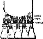
The greatest chance for overheating in the LOX system is in the transmission surface of the suction lines. Also, the suction lines are too slender for maintenance of self-contained convection currents. This situation is unacceptable since intense boiling can lead to LOX geysering, which in turn can dam­age the LOX tank structurally. In addition, too high a LOX temperature near the engine inlets can cause a cavity in the LOX pumps and interfere with nor­mal engine starting. Emergency bubbling or thermal pumping is used to correct this situation.

The bubbling technique sends helium into all five suction lines to cool the LOX rapidly. Ground sup­port supplies helium through an umbilical coupling, and filter valves and orifices control the flow of helium into the suction lines. Thermal pumping is a term used to define pumping relatively cold LOX from the LOX tank into the suction lines.

Gas Generator Valve

The gas generator valve is a hydraulically oper­ated valve which controls and sequences entry of propellants into the gas generator. Hydraulic fuel is recirculated through a passage in the valve hous­ing to maintain seal integrity and to prevent the fuel in the fuel ball housing from freezing. Fuel is also recirculated through a passage in the piston between the opening port and the closing port to prevent the piston О-ring from freezing.

3-4


SATURN V NEWS REFERENCE

Подпись: 3-5

image62

R-5

Gas Generator Assembly Including Control Valves

Gas Generator Injector

The gas generator injector directs fuel and oxi­dizer into the gas generator combustion chamber. It is a flat-faced, multi-orificed injector incorporat­ing a dome, a plate, a ring manifold, five oxidizer rings, five fuel rings, and a fuel disc. The gas gen­erator valve and the gas generator injector fuel inlet housing tee are mounted on the injector.

Fuel enters the injector through the gas generator fuel inlet housing tee from the gas generator valve. The fuel is directed through internal passages in the plate and injected into the combustion chamber through orifices in the fuel rings and the disc. Some of the orifices in the outer fuel ring also provide a cooling film of fuel for the combustion chamber wall. Oxidizer enters the injector through the oxi­dizer inlet manifold from the gas generator valve. The oxidizer is directed from the oxidizer manifold through internal passages in the plate and is in­jected into the combustion chamber through the orifices in the oxidizer rings.

Gas Generator Combustion Chamber

The gas generator combustion chamber provides a space for burning propellants and exhausts the gases from the burning propellants into the turbopump turbine manifold. It is a single-wall chamber located between the gas generator injector and the turbo­pump inlet.

PROPELLANT LEVEL MONITORING SUBSYSTEM

The propellant level monitoring subsystem checks the level of propellants in both tanks to provide checkpoints for the sensors used in the propellant utilization and loading subsystems and to monitor propellant levels during firing. These functions are performed by sensors mounted on continuous Stillwells adjacent or parallel to the full-length capacitance probes in each tank. There are 14 sen­sors on each Stillwell to indicate various levels in the tanks.

ULLAGE MOTORS

The solid propellant ullage motors are used to pro­vide artificial gravity by momentarily accelerating the second stage forward after first stage burnout. This moment of forward thrust is required in the weightless environment of outer space to make certain that the liquid propellant is in proper posi­tion to be drawn into the pumps prior to starting of the second stage engines.

4-10


SATURN V NEWS REFERENCE

image89

Eight ullage motors are utilized on the stage where they are attached around the periphery of the inter­stage structure between the first and second stages. Each ullage motor measures 12.5 inches in diameter by 89 inches long and each provides 22,500 pounds of thrust for approximately 4 seconds. The motors utilize Flexadyne solid propellant in a formulation developed specifically to provide high performance and superior mechanical properties under operat­ing conditions encountered in space. Ullage motor nozzles are canted 10 degrees to reduce exhaust impingement against the interstage structure.

THERMAL CONTROL SYSTEM

Thermal control is provided by a ground-operated system which maintains proper temperatures for the equipment containers in the forward and aft skirt areas. Tempered air is used to cool the con­tainers before propellant loading. With prepara­tion for loading, the air is changed to nitrogen for container inerting and heating. Separate thermal control systems are provided for the forward and aft skirt areas. Each of the units contains a single manifold connected to each container, individual fixed-flow orifices, and individual relief holes from each container. Container insulation and thermal inertia preclude excessive temperature changes.

J-2 ENGINE

J-2 ENGINE DESCRIPTION

The Rocketdyne J-2 engine is a high performance, upper stage, propulsion system utilizing liquid hy­drogen and liquid oxygen propellants and devel – opes a maximum vacuum thrust of 225,000 pounds.

All J-2 engines are identical when delivered and may be allocated to either the second or third stage. Each engine is equipped to be restarted in flight. However, the restart capability will be utilized only in the third stage.

The single J-2 engine used in the third stage is gimbal-mounted so that it can be moved in flight and used to steer the stage. Five J-2 engines are arranged in a cluster in the second stage. The four outboard engines of the five-engine cluster are gimbal-mounted to provide the vehicle with pitch, yaw, and roll control. The center engine is mounted in a fixed position.

Major systems of the J-2 engine include a thrust chamber and gimbal assembly system, propellant feed system, gas generator and exhaust system, electrical and pneumatic control system, start tank assembly system, and flight instrumentation system.

Thrust Chamber and Gimbal System

The J-2 engine thrust chamber serves as a mount for all engine components. It is composed of the following subassemblies: thrust chamber body, in­jector and dome assembly, gimbal bearing assembly, and augmented spark igniter.

Thrust is transmitted through the gimbal mounted on the thrust chamber assembly dome to the vehicle thrust frame structure. The thrust chamber injec­tor receives the propellants from a dual turbopump system (oxidizer and fuel) under pressure, mixes the propellants, and burns them to impart a high velocity to the expelled combustion gases to pro­duce thrust.

THRUST CHAMBER

The thrust chamber is constructed of stainless steel tubes of 0.012-inch wall thickness. Tubes with thin walls are required for heat transfer purposes. The thrust chamber tubes are stacked longitudi­nally and furnace-brazed to form a single unit. The chamber is bell-shaped with a 27.5 to 1 expansion area ratio for efficient operation at altitude, and is regeneratively cooled by the fuel. Fuel enters from a manifold located midway between the thrust

SATURN V NEWS REFERENCE

image124

R-IO

J-2 Assembly—Hydrogen fueled J-2 rocket engines for upper stages of Saturn V vehicles are completed on this assembly line. J-2 develops a maximum thrust of 225,000 pounds.

HUNTSVILLE FACILITIES

Подпись: H-5'31246 Подпись: H-40246

New Saturn V facilities built at the Marshall Space Flight Center at Huntsville, Ala., include the first stage static test stand, an F-l engine test stand, the Saturn V launch vehicle dynamic test stand, a J-2 engine facility, and ground support and component test positions.

The Marshall Center has completed a $39 million addition to its Test Laboratory for captive testing the Saturn V booster and F-l engines. The Test Laboratory addition is called the West Test Area. The largest structure in the area is the first stage test stand. Completed in 1964, the stand has an overall height of 405 feet.

image169

H-5-31176

Growth at Huntsville—The growth of rocket testing facilities at the Marshall Space Flight Center is contrasted here by the size of the first Redstone Arsenal test stand, second from left, and stands at right built for the Saturn V program.

The nearby single engine test stand is being used for research and development tests of the 1.5 million pound thrust F-l engine.

Control and monitoring equipment for the first stage and F-l engine stands is located in the area’s central blockhouse. Water needed to cool the flame deflectors of the two stands is pumped from a near­by high-pressure industrial water station.

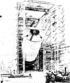
The 365-foot tall Saturn V launch vehicle was placed in another unique Marshall Center test facility — the Dynamic Test Stand. Testing of the complete three stage vehicle and its Apollo spacecraft here was done to determine its bending and vibration characteristics. Tallest of Marshall Center’s tall towers, the dynamic test stand is 98 feet square.

Several tests of the liquid hydrogen-liquid oxygen powered engine have been conducted during the past year in Marshall’s J-2 engine test facility. Tank­age for the facility is a battleship version of the Saturn V third stage. The J-2 engine stand is 156 feet tall and has a base of 34 by 68 feet. It is located in the MSFC’s East Test Area.

Vibration Version – A ground test version of the Saturn V first stage moves through the West Test Area of the Marshall Space Flight Center. The large dynamic test stage was built to undergo vibration and bending tests. Test stand at right Is a single F-l engine facility.

I

Positioning—A Saturn V first stage is placed into a test stand at Marshall Space Flight Center.

8-7


SATURN V NEWS REFERENCE

A portion of the Kennedy Space Center “spaceport” has been created at the Marshall Center’s ground support equipment test facility to check out giant mechanical swing arms which will be used on Launch Complex 39 to connect the Apollo/Saturn V space vehicle to the launcher tower. The 18-acre facility has eight swing arm test positions and one position for testing access arms to be used by Apollo astro­nauts.

Also built at Marshall are an F-l engine turbopump position in the East Test Area and a load test facil­ity in the Propulsion and Vehicle Engineering Lab­oratory.

A new Saturn V rocket “electrical simulator” or breadboard facility at the Marshall Center dupli­cates the electrical operation of the vehicle. Ele­ments simulated include the first stage booster, second stage, third stage, and an instrument unit.

Other Saturn V facilities at the Marshall Center include a booster checkout area, two new assembly areas and a components acceptance building.

image170

H-5-23531

image171

H-MTF-2077