Category Facing the Heat Barrier: a History of Hypersonics

Gemini and Apollo

An Apollo spacecraft, returning from the Moon, had twice the kinetic energy of a flight in low orbit and an aerodynamic environment that was nearly three times as severe. Its trajectory also had to thread a needle in its accuracy. Too steep a return would subject its astronauts to excessive g-forces. Too shallow a re-entry meant that it would show insufficient loss of speed within the upper atmosphere and would fly back into space, to make a final entry and then land at an unplanned location. For a simple ballistic trajectory, this “corridor” was as little as seven miles wide, from top to bottom.59

At the outset, these issues raised two problems that were to be addressed in flight test. The heat shield had to be qualified, in tests that resembled those of the X-17 but took place at much higher velocity. In addition, it was necessary to show that a re-entering spacecraft could maneuver with some precision. It was vital to broaden the corridor, and the only way to do this was to use lift. This meant demonstrat­ing successful maneuvers that had to be planned in advance, using data from tests in ground facilities at near-orbital speeds, when such facilities were most prone to error.

Apollo’s Command Module, which was to execute the re-entry, lacked wings. Still, spacecraft of this general type could show lift-to-drag ratios of 0.1 or 0.2 by flying at a nonzero angle of attack, thereby tilting the heat shield and turning it into a lifting surface. Such values were far below those achievable with wings, but they brought useful flexibility during re-entry by permitting maneuver, thereby achiev­ing a more accurate splashdown.

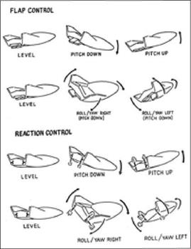
As early as 1958, Faget and his colleagues had noted three methods for trimming a capsule to a nonzero angle. Continuous thrust from a reaction-control system could do this, tilting the craft from its equilibrium attitude. A drag flap could do it as well by producing a modest amount of additional air resistance on one side of the vehicle. The simplest method required no onboard mechanism that might fail in flight and that expended no reaction-control propellant. It called for nothing more than a nonsymmetrical distribution of weight within the spacecraft, creating an offset in the location of the center of gravity. During re-entry, this offset would trim the craft to a tilted attitude, again automatically, due to the extra weight on one side. An astronaut could steer his capsule by using attitude control to roll it about its long axis, thereby controlling the orientation of the lift vector.60

This center-of-gravity offset went into the Gemini capsules that followed those of Project Mercury. The first manned Gemini flight carried the astronauts Virgil “Gus” Grissom and John Young on a three-orbit mission in March 1965. Following re-entry, they splashed down 60 miles short of the carrier USS Intrepid, which was on the aim point. This raised questions as to the adequacy of the preflight hyper­sonic wind-tunnel tests that had provided estimates of the spacecraft L/D used in mission planning.

The pertinent data had come from only two facilities. The Langley 11-inch tunnel had given points near Mach 7, while an industrial hotshot installation cov­ered Mach 15 to 22, which was close to orbital speed. The latter facility lacked instruments of adequate precision and had produced data points that showed a large scatter. Researchers had averaged and curve-fit the measurements, but it was clear that this work had introduced inaccuracies.61

During that year flight data became available from the Grissom-Young mission and from three others, yielding direct measurements of flight angle of attack and L/D. To resolve the discrepancies, investigators at the Air Forces Arnold Engineer­ing Development Center undertook further studies using two additional facilities. Tunnel F, a hotshot, had a 100-inch-diameter test section and reached Mach 20, heating nitrogen with an electric arc and achieving run times of 0.05 to 0.1 seconds. Tunnel L was a low-density, continuous-flow installation that also used arc-heated nitrogen. The Langley 11 -inch data was viewed as valid and was retained in the reanalysis.

This work gave an opportunity to benchmark data from continuous-flow and hotshot tunnels against flight data, at very high Mach numbers. Size did not matter, for the big Tunnel F accommodated a model at one-fifteenth scale that incorpo­rated much detail, whereas Tunnel L used models at scales of 1/120 and 1/180, the latter being nearly small enough to fit on a tie tack. Even so, the flight data points gave a good fit to curves derived using both tunnels. Billy Griffith, supervising the tests, concluded: “Generally, excellent agreement exists” between data from these sources.

The preflight data had brought estimated values of L/D that were too high by 60 percent. This led to a specification for the re-entry trim angle that proved to be off by 4.7 degrees, which produced the miss at splashdown. Julius Lukasiewicz, long­time head of the Von Karman Gas Dynamics Facility at AEDC, later added that if AEDC data had been available prior to the Grissom-Young flight, “the impact point would have been predicted to within ±10 miles.”62

The same need for good data reappeared during Apollo. The first of its orbital missions took place during 1966, flying atop the Saturn I-B. The initial launch, designated AS-201, flew suborbitally and covered 5,000 miles. A failure in the reac­tion controls produced uncontrolled lift during entry, but the craft splashed down 38 miles from its recovery ship. AS-202, six months later, was also suborbital. It executed a proper lifting entry—and undershot its designated aim point by 205 miles. This showed that its L/D had also been mispredicted.63

Estimates of the Apollo L/D had relied largely on experimental data taken during 1962 at Cornell Aeronautical Laboratory and Mach 15.8, and at AEDC and Mach 18.7- Again these measurements lacked accuracy, and once more Billy Griffith of AEDC stepped forward to direct a comprehensive set of new measurements. In addition to Tunnels F and L, used previously, the new work used Tunnels A, B, and C, which with the other facilities covered a range from Mach 3 to 20. To account for effects due to model supports in the wind tunnels, investigators also used a gun range that fired small models as free-flight projectiles, at Mach 6.0 to 8.5.

The 1962 estimates of Apollo L/D proved to be off by 20 percent, with the trim angle being in error by 3 degrees.64 As with the Gemini data, these results showed anew that one could not obtain reliable data by working with a limited range of facilities. But when investigators broadened their reach to use more facili­ties, and sought accuracy through such methods as elimination of model-support errors, they indeed obtained results that matched flight test. This happened twice, with both Gemini and Apollo, with researchers finally getting the accurate estimates they needed.

These studies dealt with aerodynamic data at hypervelocity. In a separate series, other flights sought data on the re-entry environment that could narrow the range of acceptable theories of hypervelocity heating. Two such launches constituted Proj­ect Fire, which flew spacecraft that were approximately two feet across and had the general shape of Apollo’s Command Module. Three layers of beryllium served as calorimeters, with measured temperature rises corresponding to total absorbed heat. Three layers of phenolic-asbestos alternated with those layers to provide thermal protection. Windows of fused quartz, which is both heat-resistant and transparent over a broad range of optical wavelengths, permitted radiometers to directly observe the heat flux due to radiation, at selected locations. These included the nose, where heating was most intense.

The Fire spacecraft rode atop Atlas boosters, with flights taking place in April 1964 and May 1965. Following cutoff of the Atlas, an Antares solid-fuel booster, modified from the standard third stage of the Scout booster, gave the craft an addi­tional 17,000 feet per second and propelled it into the atmosphere at an angle of nearly 15 degrees, considerably steeper than the range of angles that were acceptable for an Apollo re-entry. This increased the rate of heating and enhanced the contri­bution from radiation. Each beryllium calorimeter gave useful data until its outer surface began to melt, which took only 2.5 seconds as the heating approached its maximum. When decelerations due to drag reached specified levels, an onboard controller ejected the remnants of each calorimeter in turn, along with its underly­ing layer of phenolic-asbestos. Because these layers served as insulation, each ejec­tion exposed a cool beryllium surface as well as a clean set of quartz windows.

Fire 1 entered the atmosphere at 38,000 feet per second, markedly faster than the 35,000 feet per second of operational Apollo missions. Existing theories gave a range in estimates of total peak heating rate from 790 to 1,200 BTU per square foot – second. The returned data fell neatly in the middle of this range. Fire 2 did much the same, re-entering at 37,250 feet per second and giving a measured peak heating rate of just over 1,000 BTU per square foot-second. Radiative heating indeed was significant, amounting to some 40 percent of this total. But the measured values, obtained by radiometer, were at or below the minimum estimates obtained using existing theories.65

Earlier work had also shown that radiative heating was no source of concern. The new work also validated the estimates of total heating that had been used in designing the Apollo heat shield. A separate flight test, in August 1964, placed a small vehicle—the R-4—atop a five-stage version of the Scout. As with the X-17, this fifth stage ignited relatively late in the flight, accelerating the test vehicle to its peak speed when it was deep in the upper atmosphere. This speed, 28,000 feet per second, was considerably below that of an Apollo entry. But the increased air density subjected this craft to a particularly high heating rate.56

This was a materials-testing flight. The firm of Avco had been developing abla­tors of lower and lower weight and had come up with its 5026-39 series. They used epoxy-novolac as the resin, with phenolic microballoons added to the silica-fiber filler of an earlier series. Used with a structural honeycomb made of phenolic rein­forced with fiberglass, it cut the density to 35 pounds per cubic foot and, with sub­sequent improvements, to as little as 31 pounds per cubic foot. This was less than three-tenths the density of the ancestral phenolic-fiberglass of Mercury—which merely orbited the Earth and did not fly back from the Moon.67

The new material had the designation Avcoat 5026-39G. The new flight sought to qualify it under its most severe design conditions, corresponding to re-entry at the bottom of the corridor with deceleration of 20 g. The peak aerodynamic load occurred at Mach 16.4 and 102,000 feet. Observed ablation rates proved to be much higher than expected. In fact, the ablative heat shield eroded away completely! This caused serious concern, for if that were to happen during a manned mission, the spacecraft would burn up in the atmosphere and would kill its astronauts.68

The relatively high air pressure had subjected the heat shield to dynamic pres­sures three times higher than those of an Apollo re-entry. Those intense dynamic pressures corresponded to a hypersonic wind that had blown away the ablative char soon after it had formed. This char was important; it protected the underlying virgin ablator, and when it was severely thinned or removed, the erosion rate on the test heat shield increased markedly.

Much the same happened in October 1965, when another subscale heat shield underwent flight test atop another multistage solid rocket, the Pacemaker, that accelerated its test vehicle to Mach 10.6 at 67,500 feet. These results showed that failure to duplicate the true re-entry environment in flight test could introduce unwarranted concern, causing what analysts James Pavlosky and Leslie St. Leger described as “unnecessary anxiety and work.”69

An additional Project Fire flight could indeed have qualified the heat shield under fully realistic re-entry conditions, but NASA officials had gained confidence through their ability to understand the quasi-failure of the R-4. Rather than con­duct further ad hoc heat-shield flight tests, they chose to merge its qualification with unmanned flights of complete Apollo spacecraft. Following three shots aboard the

Saturn I-B that went no further than earth orbit, and which included AS-201 and -202, the next flight lifted off in November 1967. It used a Saturn V to simulate a true lunar return.

No larger rocket had ever flown. This one was immense, standing 36 stories tall. The anchorman Walter Cronkite gave commentary from a nearby CBS News studio, and as this behemoth thundered upward atop a dazzling pillar of yellow – white flame, Cronkite shouted, “Oh, my God, our building is shaking! Part of the roof has come in here!” The roar was as loud as a major volcanic eruption. People saw the ascent in Jacksonville, 150 miles away.70

Heat-shield qualification stood as a major goal. The upper stages operated in sequence, thrusting the spacecraft to an apogee of 11,242 miles. It spent several hours coasting, oriented with the heat shield in the cold soak of shadow to achieve the largest possible thermal gradient around the shield. Re-ignition of the main engine pushed the spacecraft into re-entry at 35,220 feet per second relative to the atmosphere of the rotating Earth. Flying with an effective L/D of 0.365, it came down 10 miles from the aim point and only six miles from the recovery ship, close enough for news photos that showed a capsule in the water with one of its chutes still billowing.

The heat shield now was ready for the Moon, for it had survived a peak heating rate of 425 BTU per square foot-second and a total heat load of 37,522 BTU per pound. Operational lunar flights imposed loads and heating rates that were mark­edly less demanding. In the words of Pavlosky and St. Leger, “the thermal protection subsystem was overdesigned.”71

A 1968 review took something of an offhand view of what once had been seen as an extraordinarily difficult problem. This report stated that thermal performance of ablative material “is one of the lesser criteria in developing a TPS.” Significant changes had been made to enhance access for inspection, relief of thermal stress, manufacturability, performance near windows and other penetrations, and control of the center of gravity to achieve design values of L/D, “but never to obtain better thermal performance of the basic ablator.”72

Thus, on the eve of the first lunar landing, specialists in hypersonics could look at a technology of re-entry whose prospects had widened significantly. A suite of materials now existed that were suitable for re-entry from orbit, having high emis – sivity to keep the temperature down, along with low thermal conductivity to pre­vent overheating during the prolonged heat soak. Experience had shown how care­ful research in ground facilities could produce reliable results and could permit maneuvering entry with accuracy in aim. This had been proven to be feasible for missions as demanding as lunar return.

Dyna-Soar had not flown, but it introduced metallic hot structures that brought the prospect of reusability. It also introduced wings for high L/D and particular

freedom during maneuver. Indeed, by 1970 there was only one major frontier in re-entry: the development of a lightweight heat shield that was simpler than the hot structure of Dyna-Soar and was reusable. This topic was held over for the following decade, amid the development of the space shuttle.

Gemini and Apollo

Scramjets Take Flight

On 28 November 1991 a Soviet engine flew atop an SA-5 surface-to-air mis­sile in an attempt to demonstrate supersonic combustion. The flight was launched from the Baikonur center in Kazakhstan and proceeded ballistically, covering some 112 miles. The engine did not produce propulsive thrust but rode the missile while mounted to its nose. The design had an axisymmetric configuration, resembling that of NASA’s Hypersonic Research Engine, and the hardware had been built at Moscow’s Central Institute of Aviation Motors (СІАМ).

As described by Donat Ogorodnikov, the center director, the engine performed two preprogrammed burns during the flight. The first sought to demonstrate the important function of transition from subsonic to supersonic combustion. It was initiated at 59,000 feet and Mach 3-5, as the rocket continued to accelerate. Ogoro­dnikov asserted that after fifteen seconds, near Mach 5, the engine went over to supersonic combustion and operated in this mode for five seconds, while the rocket accelerated to Mach 6 at 92,000 feet. Within the combustor, internal flow reached a measured speed of Mach 3. Pressures within the combustor were one to two atmo­spheres.

Scramjets Take Flight

The second engine burn lasted ten seconds. This one had the purpose of verify­ing the design of the engine’s ignition system. It took place on the downward leg of the trajectory, as the vehicle descended from 72,000 feet and Mach 4.5 to 59,000 feet and Mach 3.5. This burn involved only subsonic combustion. Vyacheslav Vino­gradov, chief of engine gasdynamics at СІАМ, described the engine as mounting three rows of fuel injectors. Choice of an injector row, out of the three available, was to help in changing the combustion mode.

The engine diameter at the inlet was 9.1 inches; its length was 4.2 feet. The spike, inlet, and combustor were of stainless steel, with the spike tip and cowl lead­

ing edge being fabricated using powder metallurgy. The fuel was liquid hydrogen, and the system used no turbopump. Pressure, within a fuel tank that also was stain­less steel, forced the hydrogen to flow. The combustor was regeneratively cooled; this vaporized the hydrogen, which flowed through a regulator at rates that varied from 0.33 pounds per second in low-Mach flight to 0.11 at high Mach.42

The Russians made these extensive disclosures because they hoped for financial support from the West. They obtained initial assistance from France and conducted a second flight test a year later. The engine was slightly smaller and the trajectory was flatter, reaching 85,000 feet. It ignited near Mach 3-5 and sustained subsonic combustion for several seconds while the rocket accelerated to Mach 5. The engine then transitioned to supersonic combustion and remained in this mode for some fifteen seconds, while acceleration continued to Mach 5-5. Burning then terminated due to exhaustion of the fuel.43

On its face, this program had built a flightworthy scramjet, had achieved a super­sonic internal airflow, and had burned hydrogen within this flow. Even so, this was not necessarily the same as accomplishing supersonic combustion. The alleged tran­sition occurred near Mach 5, which definitely was at the low end for a scramjet.44 In addition, there are a number of ways whereby pockets of subsonic flow might have existed within an internal airstream that was supersonic overall. These could have served as flameholders, localized regions where conditions for combustion were par­ticularly favorable.45

In 1994 СІАМ received a contract from NASA, with NASA-Langley providing technical support. The goal now was Mach 6.5, at which supersonic combustion appeared to hold a particularly strong prospect. The original Russian designs had been rated for Mach 6 and were modified to accommodate the higher heat loads at this higher speed. The flight took place in February 1998 and reached Mach 6.4 at

70,0 feet, with the engine operating for 77 seconds.46

It began operation near Mach 3-5. Almost immediately the inlet unstarted due to excessive fuel injection. An onboard control system detected the unstart and reduced the fuel flow, which enabled the inlet to start and to remain started. How­ever, the onboard control failed to detect this restart and failed to permit fuel to flow through the first of the three rows of fuel injectors. Moreover, the inlet performance fell short of predictions due to problems in fabrication.

At Mach 5-5 and higher, airflow entered the fuel-air mixing zone within the combustor at speeds near Mach 2. However, only the two rear rows of injectors were active, and burning of their fuel forced the internal Mach number to subsonic values. The flow reaccelerated to sonic velocity at the combustor exit. The combina­tion of degraded inlet performance and use of only the rear fuel injectors ensured that even at the highest flight speeds, the engine operated primarily in a subsonic – combustion mode and showed little if any supersonic combustion.47

It nevertheless was clear that with better quality control in manufacturing and with better fault tolerance in the onboard control laws, full success might readily be achieved. However, the СІАМ design was axisymmetric and hence was of a type that NASA had abandoned during the early 1970s. Such scramjets had played no role in NASP, which from the start had focused on airframe-integrated configura­tions. The СІАМ project had represented an existing effort that was in a position to benefit from even the most modest of allocations; the 1992 flight, for instance, received as little as $200,000 from France.48 But NASA had its eye on a completely American scramjet project that could build on the work of NASP. It took the name Hyper-X and later X-43A.

Its background lay in a 1995 study conducted by McDonnell Douglas, with Pratt & Whitney providing concepts for propulsion. This effort, the Dual-Fuel Airbreathing Hypersonic Vehicle Study, gave conceptual designs for vehicles that could perform two significant missions: weapons delivery and reconnaissance, and operation as the airbreathing first stage of a two-stage-to-orbit launch system. This work drew interest at NASA Headquarters and led the Hypersonic Vehicles Office at NASA-Langley to commission the conceptual design of an experimental airplane that could demonstrate critical technologies required for the mission vehicles.

The Hyper-X design grew out of a concept for a Mach 10 cruise aircraft with length of 200 feet and range of 8,500 nautical miles. It broke with the NASP approach of seeking a highly integrated propulsion package that used an ejector ramLACE as a low-speed system. Instead it returned to the more conservative path of installing separate types of engine. Hydrocarbon-fueled turboramjets were to serve for takeoff, acceleration to Mach 4, and subsonic cruise and landing. Hydro­gen-burning scramjets were to take the vehicle to Mach 10. The shape of this vehicle defined that of Hyper-X, which was designed as a detailed scale model that was 12 feet long rather than 200.49

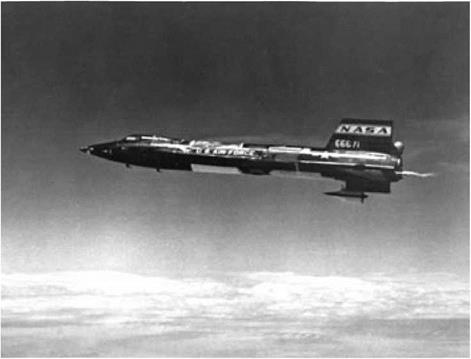
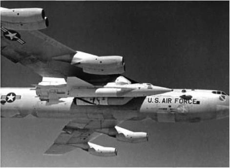
Like the Russian engines, Hyper-X was to fly to its test Mach using a rocket booster. But Hyper-X was to advance beyond the Russian accomplishments by sepa­rating from this booster to execute free flight. This separation maneuver proved to be trickier than it looked. Subsonic bombers had been dropping rocket planes into flight since the heyday of Chuck Yeager, and rocket stages had separated in near­vacuum at the high velocities of a lunar mission. However, Hyper-X was to separate at speeds as high as Mach 10 and at 100,000 feet, which imposed strong forces from the airflow. As the project manager David Reubush wrote in 1999, “To the programs knowledge there has never been a successful separation of two vehicles (let alone a separation of two non-axisymmetric vehicles) at these conditions. Therefore, it soon became obvious that the greatest challenge for the Hyper-X program was, not the design of an efficient scramjet engine, but the development of a separation scenario and the mechanism to achieve it.”50

Engineers at Sandia National Laboratory addressed this issue. They initially envisioned that the rocket might boost Hyper-X to high altitude, with the sepa­ration taking place in near-vacuum. The vehicle then could re-enter and light its scramjet. This approach fell by the wayside when the heat load at Mach 10 proved to exceed the capabilities of the thermal protection system. The next concept called for Hyper-X to ride the underside of its rocket and to be ejected downward as if it were a bomb. But this vehicle then would pass through the bow shock of the rocket and would face destabilizing forces that its control system could not counter.

Sandia’s third suggestion called for holding the vehicle at the front of the rocket using a hinged adapter resembling a clamshell or a pair of alligator jaws. Pyrotech­nics would blow the jaws open, releasing the craft into flight. The open jaws then were to serve as drag brakes, slowing the empty rocket casing while the flight vehicle sailed onward. The main problem was that if the vehicle rolled during separation, one of its wings might strike this adapter as it opened. Designers then turned to an adapter that would swing down as a single piece. This came to be known as the “drop-jaw,” and it served as the baseline approach for a time.51

NASA announced the Hyper-X Program in October 1996, citing a budget of $170 million. In February 1997 Orbital Sciences won a contract to provide the rocket, which again was to be a Pegasus. A month later the firm of Micro Craft Inc. won the contract for the Hyper-X vehicle, with GASL building the engine. Work at GASL went forward rapidly, with that company delivering a scramjet to NASA – Langley in August 1998. NASA officials marked the occasion by changing the name of the flight aircraft to X-43A.52

The issue of separation in flight proved not to be settled, however, and develop­ments early in 1999 led to abandonment of the drop-jaw. This adapter extended forward of the end of the vehicle, and there was concern that while opening it would form shock waves that would produce increased pressures on the rear underside of the flight craft, which again could overtax its control system. Wind-tunnel tests showed that this indeed was the case, and a new separation mechanism again was necessary. This arrangement called for holding the X-43A in position with explo­sive bolts. When they were fired, separate pyrotechnics were to actuate pistons that would push this craft forward, giving it a relative speed of at least 13 feet per second. Further studies and experiments showed that this concept indeed was suitable.53

The minimal size of the X-43A meant that there was little need to keep its weight down, and it came in at 2,800 pounds. This included 900 pounds of tungsten at the nose to provide ballast for stability in flight while also serving as a heat sink. High stiffness of the vehicle was essential to prevent oscillations of the structure that could interfere with the Pegasus flight control system. The X-43A thus was built with steel longerons and with steel skins having thickness of one-fourth inch. The wings were stubby and resembled horizontal stabilizers; they did not mount ailerons but moved as a whole to provide sufficient control authority. The wings and tail surfaces were constructed of temperature-resistant Haynes 230 alloy. Leading edges of the nose, vertical fins, and wings used carbon-carbon. For thermal protection, the vehicle was covered with Alumina Enhanced Thermal Barrier tiles, which resembled the tiles of the space shuttle.54

Additional weight came from the scramjet. It was fabricated of a copper alloy called Glidcop, which was strengthened with very fine particles of aluminum oxide dispersed within. This increased its strength at high temperatures, while retaining the excellent thermal conductivity of copper. This alloy formed the external surface, sidewalls, cowl, and fuel injectors. Some internal surfaces were coated with zirconia to form a thermal barrier that protected the Glidcop in areas of high heating. The engine did not use its hydrogen fuel as a coolant but relied on water cooling for the sidewalls and cowl leading edge. Internal engine seals used braided ceramic rope.55

Because the X-43A was small, its engine tests were particularly realistic. This vehicle amounted to a scale model of a much larger operational craft of the future, but the engine testing involved ground-test models that were full size for the X-43A. Most of the testing took place at NASA-Langley, where the two initial series were conducted at the Arc-Heated Scramjet Test Facility. This wind tunnel was described in 1998 as “the primary Mach 7 scramjet test facility at Langley.”56

Development tests began at the very outset of the Hyper-X Program. The first test article was the Dual-Fuel Experiment (DFX), with a name that reflected links to the original McDonnell Douglas study. The DFX was built in 1996 by modifying existing NASP engine hardware. It provided a test scramjet that could be modified rapidly and inexpensively for evaluation of changes to the flowpath. It was fabricated primarily of copper and used no active cooling, relying on heat sink. This ruled out tests at the full air density of a flight at Mach 7, which would have overheated this engine too quickly for it to give useful data. Even so, tests at reduced air densities gave valuable guidance in designing the flight engine.

The DFX reproduced the full-scale height and length of the Hyper-X engine, correctly replicating details of the forebody, cowl, and sidewall leading edge. The forebody and afterbody were truncated, and the engine width was reduced to 44 percent of the true value so that this test engine could fit with adequate clearances in the test facility. This effort conducted more than 250 tests of the DFX, in four dif­ferent configurations. They verified predicted engine forces and moments as well as inlet and combustor component performances. Other results gave data on ignition requirements, flameholding, and combustor-inlet interactions.

Within that same facility, subsequent tests used the Hyper-X Engine Module (HXEM). It resembled the DFX, including the truncations fore and aft, and it too was of reduced width. But it replicated the design of the flight engine, thereby overcoming limitations of the DFX. The HXEM incorporated the active cooling of

the flight version, which opened the door to tests at Mach 7 and at full air density. These took place within the large Eight-Foot High Temperature Tunnel (HTT).

The HTT had a test section that was long enough to accommodate the full 12- foot length of the X-43A underside, which provided major elements of the inlet and nozzle with its airframe-integrated forebody and afterbody. This replica of the underside initially was tested with the HXEM, thereby giving insight into the aero­dynamic effects of the truncations. Subsequent work continued to use the HTT and replaced the HXEM with the full-width Hyper-X Flight Engine (HXFE). This was a flight-spare Mach 7 scramjet that had been assigned for use in ground testing.

Mounted on its undersurface, this configuration gave a geometrically accurate nose-to-tail X-43A propulsion flowpath at full scale. NASA-Langley had conducted previous tests of airframe-integrated scramjets, but this was the first to replicate the size and specific details of the propulsion system of a flight vehicle. The HTT heated its air by burning methane, which added large quantities of carbon dioxide and water vapor to the test gas. But it reproduced the Mach, air density, pressure, and temperature of flight at altitude, while gaseous oxygen, added to the airflow, enabled the engine to burn hydrogen fuel. Never before had so realistic a test series been accomplished.57

The thrust of the engine was classified, but as early as 1997 Vince Rausch, the Hyper-X manager at NASA-Langley, declared that it was the best-performing scram­jet that had been tested at his center. Its design called for use of a cowl door that was to protect the engine by remaining closed during the rocket-powered ascent, with this door opening to start the inlet. The high fidelity of the HXFE, and of the test conditions, gave confidence that its mechanism would work in flight. The tests in the HTT included 14 unfueled runs and 40 with fuel. This cowl door was actu­ated 52 times under the Mach 7 test conditions, and it worked successfully every time.58

Aerodynamic wind-tunnel investigations complemented the propulsion tests and addressed a number of issues. The overall program covered all phases of the flight trajectory, using 15 models in nine wind tunnels. Configuration development alone demanded more than 5,800 wind-tunnel runs. The Pegasus rocket called for evaluation of its own aerodynamic characteristics when mated with the X-43A, and these had to be assessed from the moment of being dropped from the B-52 to sepa­ration of the flight vehicle. These used the Lockheed Martin Vought High Speed Wind Tunnel in Grand Prairie, Texas, along with facilities at NASA-Langley that operated at transonic as well as hypersonic speeds.59

Much work involved evaluating stability, control, and performance character­istics of the basic X-43A airframe. This effort used wind tunnels of McDonnell Douglas and Rockwell, with the latter being subsonic. At NASA-Langley, activity focused on that center’s 20-inch Mach 6 and 31-inch Mach 10 facilities. The test models were only one foot in length, but they incorporated movable rudders and wings. Eighteen-inch models followed, which were as large as these tunnels could accommodate, and gave finer increments of the control-surface deflections. Thirty – inch models brought additional realism and underwent supersonic and transonic tests in the Unitary Plan Wind Tunnel and the 16-Foot Transonic Tunnel.60

Similar studies evaluated the methods proposed for separation of the X-43A from its Pegasus booster. Initial tests used Langley’s Mach 6 and Mach 10 tunnels. These were blowdown facilities that did not give long run times, while their test sections were too small to permit complete representations of vehicle maneuvers during separation. But after the drop-jaw concept had been selected, testing moved to tunnel В of the Von Karman Facility at the Arnold Engineering Development Center. This wind tunnel operated with continuous flow, in contrast to the blow­down installations of Langley, and provided a 50-inch-diameter test section for use at Mach 6. It was costly to test in that tunnel but highly productive, and it accom­modated models that demonstrated a full range of relative orientations of Pegasus and the X-43A during separation.61

This wind-tunnel work also contributed to inlet development. To enhance overall engine performance, it was necessary for the boundary layer upstream of this inlet to be turbulent. Natural transition to turbulence could not be counted on, which meant that an aerodynamic device of some type was needed to trip the boundary layer into turbulence. The resulting investigations ran from 1997 into 1999 and used both the Mach 6 and Mach 10 Langley wind tunnels, executing more than 300 runs. Hypulse, a shock tunnel at GASL, conducted more than two dozen additional tests.62

Computational fluid dynamics was used extensively. The wind-tunnel tests that supported studies of X-43A separation all were steady-flow experiments, which failed to address issues such as unsteady flow in the gap between the two vehicles as they moved apart. CFD dealt with this topic. Other CFD analyses examined relative orientations of the separating vehicles that were not studied at AEDC. To scale wind-tunnel results for use with flight vehicles, CFD solutions were generated both for the small models under wind-tunnel conditions and for full-size vehicles in flight.63

Flight testing was to be conducted at NASA-Dryden. The first X-43A flight vehi­cle arrived there in October 1999, with its Pegasus booster following in December. Tests of this Pegasus were completed in May 2000, with the flight being attempted a year later. The plan called for acceleration to Mach 7 at 95,000 feet, followed by 10 seconds of powered scramjet operation. This brief time reflected the fact that the engine was uncooled and relied on copper heat sink, but it was long enough to take data and transmit them to the ground. In the words of NASA manager Lawrence Huebner, “we have ground data, we have ground CFD, we have flight CFD—all we need is the flight data.”64

Launch finally occurred in June 2001. Ordinarily, when flying to orbit, Pega­sus was air-dropped at 38,000 feet, and its first stage flew to 207,000 feet prior to second-stage ignition. It used solid propellant and its performance could not readily be altered; therefore, to reduce its peak altitude to the 95,000 feet of the X-43A, it was to be air-dropped at 24,000 feet, even though this lower altitude imposed greater loads.

The B-52 took off from Edwards AFB and headed over the Pacific. The Pega­sus fell away; its first stage ignited five seconds later and it flew normally for some eight seconds that followed. During those seconds, it initiated a pullout to begin its climb. Then one of its elevons came off, followed almost immediately by another. As additional parts fell away, this booster went out of control. It fell tumbling toward the ocean, its rocket motor still firing, and a safety officer sent a destruct signal. The X-43A never had a chance to fly, for it never came close to launch conditions.65

A year later, while NASA was trying to recoup, a small group in Australia beat the Yankees to the punch by becoming the first in the world to fly a scramjet and achieve supersonic combustion. Their project, called HyShot, cost under $2 mil­lion, compared with $185 million for the X-43A program. Yet it had plenty of technical sophistication, including tests in a shock tunnel and CFD simulations using a supercomputer.

Allan Pauli, a University of Queensland researcher, was the man who put it together. He took a graduate degree in applied mathematics in 1985 and began working at that university with Ray Stalker, an engineer who had won a global repu­tation by building a succession of shock tunnels. A few years later Stalker suffered a stroke, and Pauli found himself in charge of the program. Then opportunity came knocking, in the form of a Florida-based company called Astrotech Space Opera­tions. That firm was building sounding rockets and wanted to expand its activities into the Asia and Pacific regions.

In 1998 the two parties signed an agreement. Astrotech would provide two Ter – rier-Orion sounding rockets; Pauli and his colleagues would construct experimental scramjets that would ride those rockets. The eventual scramjet design was not air­frame-integrated, like that of the X-43A. It was a podded axisymmetric configura­tion. But it was built in two halves, with one part being fueled with hydrogen while the other part ran unfueled for comparison.66

Pauli put together a team of four people—and found that the worst of his prob­lems was what he called an “amazing legal nightmare” that ate up half his time. In the words of the magazine Air & Space, “the team had to secure authorizations from various state government agencies, coordinate with aviation bodies and insurance companies in both Australia and the United States (because of the involvement of U. S. funding), perform environmental assessments, and ensure their launch debris would steer clear of land claimed by Aboriginal tribes…. All told, the preparations took three and a half years.”67

The flight plan called for each Terrier-Orion to accelerate its scramjet onto a ballistic trajectory that was to reach an altitude exceeding 300 kilometers. Near the peak of this flight path, an attitude-control system was to point the rocket down­ward. Once it re-entered the atmosphere, below 40 kilometers, its speed would fall off and the scramjet would ignite. This engine was to operate while continuing to plunge downward, covering distance into an increasingly dense atmosphere, until it lost speed in the lower atmosphere and crashed into the outback.

The flights took place at Woomera Instrumented Range, north of Adelaide. The first launch attempt came at the end of October 2001. It flopped; the first stage performed well, but the second stage went off course. But nine months later, on 30 July 2002, the second shot gained full success. The rocket was canted slightly away from the vertical as it leaped into the air, accelerating at 22 g as it reached Mach 3-6 in only six seconds.

This left it still at low altitude while topping the speed of the SR-71, so after the second stage with payload separated, it coasted for 16 seconds while continuing to ascend. The second stage then ignited, and this time its course was true. It reached a peak speed of Mach 7.7. The scramjet went over the top; it pointed its nose down­ward, and at an altitude of 36 kilometers with its speed approaching Mach 7.8, gaseous hydrogen caused it to begin producing thrust. This continued until HyShot reached 25 kilometers, when it shut down.

It fired for only five seconds. But it returned data over 40 channels, most of which gave pressure readings. NASA itself provided support, with Lawrence Hueb – ner, the X-43A manager, declaring, “We’re very hungry for flight data.” For the moment, at least, the Aussies were in the lead.68

But the firm of Micro Craft had built two more X-43As, and the second flight took place in March 2004. This time the Pegasus first stage had been modified by having part of its propellant removed, to reduce its performance, and the drop alti­tude was considerably higher.69 In the words of Aviation Week,

The B-52B released the 37,500-lb. stack at 40,000 ft. and the Pegasus

booster ignited 5 sec. later__ After a few seconds it pulled up and reached

a maximum dynamic pressure of 1,650 psf. at Mach 3.5 climbing through

47,0 ft. Above 65,000 ft. it started to push over to a negative angle of attack to kill the climb rate and gain more speed. Burnout was 84 sec. after drop, and at 95 sec. a pair of pistons pushed the X-43A away from the booster at a target condition of Mach 7 and 95,000 ft. and a dynamic pressure of 1,060 psf. in a slight climb before the top of a ballistic arc.

After a brief period of stabilization, the X-43A inlet door was opened

to let air in through the engine___ The X-43A stabilized again because the

engine airflow changed the trim____ Then silane, a chemical that burns

upon contact with air, was injected for 3 sec. to establish flame to ignite the

Scramjets Take Flight

X-43A mission to Mach 7. (NASA)

hydrogen. Injection of the gaseous hydrogen fuel ramped up as the silane ramped down, lasting 8 sec. The hydrogen flow rate increased through and beyond a stoichiometric mixture ratio, and then ramped down to a very lean ratio that continued to burn until the fuel was shut off…. The hydrogen was stored in 8,000-psi bottles.

Accelerometers showed the X-43A gained speed while fuel was on…. Data was gathered all the way to the splashdown 450 naut. mi. offshore at about 11 min. after drop.

Aviation Week added that the vehicle accelerated “while in a slight climb at Mach 7 and 100,000 ft. altitude. The scramjet field is sufficiently challenging that produc­ing thrust greater than drag on an integrated airframe/engine is considered a major accomplishment.”70

In this fashion, NASA executed its first successful flight of a scramjet. The overall accomplishment was not nearly as ambitious as that planned for the Incremental Flight Test Vehicle of the 1960s, for which the velocity increase was to have been much greater. Nor did NASA have a follow-on program in view that could draw on the results of the X-43A. Still, the agency now could add the scramjet to its list of flight engines that had been successfully demonstrated.

The program still had one unexpended X-43A vehicle that was ready to fly, and it flew successfully as well, in November. The goal now was Mach 10. This called for beefing up the thermal structure by adding leading edges of solid carbon-carbon to the vertical tails along with a coating of hafnium carbide and by making the nose blunter to increase the detachment of the bow shock. These changes indeed were necessary. Nose temperatures reached 3,600°F, compared with 2,600°F on the Mach 7 flight, and heating rates were twice as high.

The Pegasus rocket, with the X-43A at its front, fell away from its B-52 carrier aircraft at 40,000 feet. Its solid rocket took the combination to Mach 10 at 110,000 feet. Several seconds after burnout, pistons pushed the X-43A away at Mach 9-8. Then, 2.5 seconds after separation, the engine inlet door opened and the engine began firing at Mach 9-65. It ran initially with silane to ensure ignition; then the engine continued to operate with silane off, for comparison. It fired for a total of 10 to 12 seconds and then continued to operate with the fuel off. Twenty-one seconds after separation, the inlet door closed and the vehicle entered a hypersonic glide. This continued for 14 minutes, with the craft returning data by telemetry until it struck the Pacific Ocean and sank.

This flight gave a rare look at data taken under conditions that could not be duplicated on the ground using continuous-flow wind tunnels. The X-43A had indeed been studied in 0.005-second runs within shock tunnels, and Aviation Week noted that Robert Bakos, vice president of GASL, described such tests as having done “a very good job of predicting the flight.” Dynamic pressure during the flight was 1,050 pounds per square foot, and the thrust approximately equaled the drag. In addition, the engine achieved true supersonic combustion, without internal pockets of subsonic flow. This meant that the observations could be scaled to still higher Mach values.71

Flight Test

The first important step in this direction came in January 1955, when the Air Force issued a letter contract to Lockheed that authorized them to proceed with the X-17. It took shape as a three-stage missile, with all three stages using solid-propel­lant rocket motors from Thiokol. It was to reach Mach 15, and it used a new flight mode called “over the top.”

The X-17 was not to fire all three stages to achieve a very high ballistic trajec­tory. Instead it started with only its first stage, climbing to an altitude of 65 to 100 miles. Descent from such an altitude imposed no serious thermal problems. As it re-entered the atmosphere, large fins took hold and pointed it downward. Below 100,000 feet, the two upper stages fired, again while pointing downward. These stages accelerated a test nose cone to maximum speed, deep within the atmosphere. This technique prevented the nose cone from decelerating at high altitude, which would have happened with a very high ballistic flight path. Over-the-top also gave good control of both the peak Mach and of its altitude of attainment.

The accompanying table summarizes the results. Following a succession of sub­scale and developmental flights that ran from 1955 into 1956, the program con­ducted two dozen test firings in only eight months. The start was somewhat shaky as no more than two of the first six X-17s gained full success, but the program soon settled down to routine achievement. The simplicity of solid-propellant rock­etry enabled the flights to proceed with turnaround times of as little as four days. Launches required no more than 40 active personnel, with as many as five such flights taking place within the single month of October 1956. All of them flew from a single facility: Pad 3 at Cape Canaveral.59

Подпись: X-17 FLIGHT TESTS Date Nose-Cone Shape 17 Jul 1956 Hemisphere 27 Jul 1956 Cubic Paraboloid 18 Aug 1956 Hemisphere 23 Aug 1956 Blunt 28 Aug 1956 Blunt 8 Sep 1956 Cubic Paraboloid 1 Oct 1956 Hemisphere 5 Oct 1956 Hemisphere 13 Oct 1956 Cubic Paraboloid 18 Oct 1956 Hemisphere 25 Oct 1956 Blunt 5 Nov 1956 Blunt (Avco) 16 Nov 1956 Blunt (Avco) 23 Nov 1956 Blunt (Avco) 3 Dec 1956 Blunt (Avco) 11 Dec 1956 Blunt Cone (GE) 8 Jan 1957 Blunt Cone (GE) 15 Jan 1957 Blunt Cone (GE) 29 Jan 1957 Blunt Cone (GE) 7 Feb 1957 Blunt Cone (GE) 14 Feb 1957 Hemisphere 1 Mar 1957 Blunt Cone (GE) 11 Mar 1957 Blunt (Avco) 21 Mar 1957 Blunt (Avco)
Подпись: Results Mach 12.4 at 40,000 feet. Third stage failed to ignite. Missile exploded 18 sec. after launch. Mach 12.4 at 38,500 feet. Telemetry lost prior to apogee. Upper stages ignited while ascending. Mach 12.1 at 36,500 feet. Mach 13.7 at 54,000 feet. Mach 13.8 at 58,500 feet. Mach 12.6 at 37,000 feet. Mach 14.2 at 59,000 feet. Mach 12.6 at 41,100 feet. Mach 13.8 at 57,000 feet. Mach 11.3 at 34,100 feet. Mach 13.8 at 47,700 feet. Mach 11.4 at 34,000 feet. Mach 11.5 at 34,600 feet. Upper stages failed to ignite. Missile destroyed by Range Safety. Mach 14.4 at 57,000 feet. Mach 12.1 at 35,000 feet. Mach 11.4 at 35,600 feet. Mach 11.3 at 35,500 feet. Mach 13.2 at 54,500 feet.

Source: “Re-EntryTest Vehicle X-17,” pp. 30, 32.

Many nose cones approached or topped Mach 12 at altitudes below 40,000 feet. This was half the speed of a satellite, at altitudes where airliners fly today. One places this in perspective by noting that the SR-71 cruised above Mach 3, one-fourth this speed, and at 85,000 feet, which was more than twice as high. Thermal problems dominated its design, with this spy plane being built as a titanium hot structure. The X-15 reached Mach 6.7 in 1967, half the speed of an X-17 nose cone, and at
102,000 feet. Its structure was Inconel X heat sink, and it had further protection from a spray-on ablative. Yet it sustained significant physical damage due to high temperatures and never again approached that mark.60

Another noteworthy flight involved a five-stage NACA rocket that was to accom­plish its own over-the-top mission. It was climbing gently at 96,000 feet when the third stage ignited. Telemetry continued for an additional 8.2 seconds and then suddenly cut off, with the fifth stage still having half a second to burn. The speed was Mach 15-5 at 98,500 feet. The temperature on the inner surface of the skin was 2,500°F, close to the melting point, with this temperature rising at nearly 5,300°F per second.61

How then did X-17 nose cones survive flight at nearly this speed, but at little more than one-third the altitude? They did not. They burned up in the atmosphere. They lacked thermal protection, whether heat sink or ablative (which the Air Force, the X-17’s sponsor, had not invented yet), and no attempt was made to recover them. The second and third stages ignited and burned to depletion in only 3-7 seconds, with the thrust of these stages being 102,000 and 36,000 pounds, respec­tively.62 Acceleration therefore was extremely rapid; exposure to conditions of very high Mach was correspondingly brief. The X-17 thus amounted to a flying shock tube. Its nose cones lived only long enough to return data; then they vanished into thin air.

Yet these data were priceless. They included measurements of boundary-layer transition, heat transfer, and pressure distributions, covering a broad range of peak Mach values, altitudes, and nose-cone shapes. The information from this program complemented the data from Avco Research Laboratory, contributing materially to Air Force decisions that selected ablation for Atlas (and for Titan, a second ICBM), while retaining heat sink for Thor.63

As the X-17 went forward during 1956 and 1957, the Army weighed in with its own flight-test effort. Here were no over-the-top heroics, no ultrashort moments at high Mach with nose cones built to do their duty and die. The Army wanted nothing less than complete tests of true ablating nose cones, initially at subscale and later at full scale, along realistic ballistic trajectories. The nose cones were to survive re-entry. If possible, they were to be recovered from the sea.

The launch vehicle was the Jupiter-C, another product of Von Braun. It was based on the liquid-fueled Redstone missile, which was fitted with longer propellant tanks to extend the burning time. Atop that missile rode two additional stages, both of which were built as clusters of small solid-fuel rockets.

The first flight took place from Cape Canaveral in September 1956. It carried no nose cone; this launch had the purpose of verifying the three-stage design, par­ticularly its methods for stage separation and ignition. A dummy solid rocket rode atop this stack as a payload. All three stages fired successfully, and the flight broke all

Flight Test

Thor missile with heat-sink nose cone. (U. S. Air Force)

performance records. The payload reached a peak altitude of682 miles and attained an estimated range of 3,335 miles.64

Nose-cone tests followed during 1957- Each cone largely duplicated that of the Jupiter missile but was less than one-third the size, having a length of 29 inches and maximum diameter of 20 inches. The weight was 314 pounds, of which 83

Flight Test

Jupiter nose cone. (U. S. Army)

pounds constituted the mix of glass cloth and Micarta plastic that formed the abla­tive material. To aid in recovery in the ocean, each nose cone came equipped with a balloon for flotation, two small bombs to indicate position for sonar, a dye marker, a beacon light, a radio transmitter—and shark repellant, to protect the balloon from attack.65

The first nose-cone flight took place in May. Telemetry showed that the re-entry vehicle came through the atmosphere successfully and that the ablative thermal pro­tection indeed had worked. However, a faulty trajectory caused this nose cone to fall 480 miles short of the planned impact point, and this payload was not recovered.

Full success came with the next launch, in August. All three stages again fired, pushing the nose cone to a range of 1,343 statute miles. This was shorter than the planned range of Jupiter, 1,725 miles, but still this payload experienced 95 percent of the total heat transfer that it would have received at the tip for a full-range flight. The nose cone also was recovered, giving scientists their first close look at one that had actually survived.66

In November President Eisenhower personally displayed it to the nation. The Soviets had stirred considerable concern by placing two Sputnik satellites in orbit, thus showing that they already had an ICBM. Speaking on nationwide radio and television, Ike sought to reassure the public. He spoke of American long-range bombers and then presented his jewel: “One difficult obstacle on the way to pro­ducing a useful long-range weapon is that of bringing a missile back from outer space without its burning up like a meteor. This object here in my office is the nose cone of an experimental missile. It has been hundreds of miles into outer space and back. Here it is, completely intact.”67

Jupiter then was in flight test and became the first missile to carry a full-size nose cone to full range.68 But the range of Jupiter was far shorter than that of Atlas. The Army had taken an initial lead in nose-cone testing by taking advantage of its early start, but by the time of that flight—May 1958—all eyes were on the Air Force and on flight to intercontinental range.

Atlas also was in flight test during 1958, extending its range in small steps, but it still was far from ready to serve as a test vehicle for nose cones. To attain 5,000-mile range, Air Force officials added an upper stage to the Thor. The resulting rocket, the Thor-Able, indeed had the job of testing nose cones. An early model, from General Electric, weighed more than 600 pounds and carried 700 pounds of instruments.69

Two successful flights, both to full range, took place during July 1958. The first one reached a peak altitude of 1,400 miles and flew 5,500 miles to the South Atlantic. Telemetered data showed that its re-entry vehicle survived the fiery pas­sage through the atmosphere, while withstanding four times the heat load of a Thor heat-sink nose cone. This flight carried a passenger, a mouse named Laska in honor of what soon became the 49th state. Little Laska lived through decelerations during re-entry that reached 60 g, due to the steepness of the trajectory, but the nose cone was not recovered and sank into the sea. Much the same happened two weeks later, with the mouse being named Wickie. Again the reentry vehicle came through the atmosphere successfully, but Wickie died for his country as well, for this nose cone also sank without being recovered.70

A new series of tests went forward during 1959, as General Electric introduced the RVX-1 vehicle. Weighing 645 pounds, 67 inches long with a diameter at the base of 28 inches, it was a cylinder with a very blunt nose and a conical afterbody for stability.71 A flight in March used phenolic nylon as the ablator. This was a phenolic resin containing randomly oriented one-inch-square pieces of nylon cloth. Light weight was its strong suit; with a density as low as 72 pounds per cubic foot, it was only slightly denser than water. It also was highly effective as insulation. Following flight to full range, telemetered data showed that a layer only a quarter-inch thick could limit the temperature rise on the aft body, which was strongly heated, to less than 200°F. This was well within the permissible range for aluminum, the most familiar of aerospace materials. For the nose cap, where the heating was strongest, GE installed a thick coating of molded phenolic nylon.72

Within this new series of flights, new guidance promised enhanced accuracy and a better chance of retrieval. Still, that March flight was not recovered, with another shot also flying successfully but again sinking beneath the waves. When the first recovery indeed took place, it resulted largely from luck.

Early in April an RVX-1 made a flawless flight, soaring to 764 miles in altitude and sailing downrange to 4,944 miles. Peak speed during re-entry was Mach 20, or 21,400 feet per second. Peak heating occurred at Mach 16, or 15,000 feet per second, and at 60,000 feet. The nose cone took this in stride, but searchers failed to detect its radio signals. An Avco man in one of the search planes saved the situation by spotting its dye marker. Aircraft then orbited the position for three hours until a recovery vessel arrived and picked it up.73

It was the first vehicle to fly to intercontinental range and return for inspection. Avco had specified its design, using an ablative heat shield of fused opaque quartz. Inspection of the ablated surface permitted comparison with theory, and the results were described as giving “excellent agreement.” The observed value of maximum ablated thickness was 9 percent higher than the theoretical value. The weight loss of ablated material agreed within 20 percent, while the fraction of ablated material that vaporized during re-entry was only 3 percent higher than the theoretical value. Most of the differences could be explained by the effect of impurities on the viscos­ity of opaque quartz.74

A second complete success was achieved six weeks later, again with a range of 5,000 miles. Observers aboard a C-54 search aircraft witnessed the re-entry, acquired the radio beacon, and then guided a recovery ship to the site.75 This time the nose-cone design came from GE. That company’s project engineer, Walter Scha­fer, wanted to try several materials and to instrument them with breakwire sensors. These were wires, buried at various depths within the ablative material, that would break as it eroded away and thus disclose the rate of ablation. GE followed a sugges­tion from George Sutton and installed each material as a 60-degree segment around the cylinder and afterbody, with the same material being repeated every 180 degrees for symmetry.76

Within the fast-paced world of nose-cone studies, each year had brought at least one new flight vehicle. The X-17 had flown during 1956. For the Jupiter-C, success had come in 1957. The year 1958 brought both Jupiter and the Thor-Able. Now, in 1959, the nose-cone program was to gain final success by flying full-size re-entry vehicles to full range aboard Atlas.

The program had laid important groundwork in November 1958, when this missile first flew to intercontinental distance. The test conductor, with the hopeful name of Bob Shotwell, pushed the button and the rocket leaped into the night. It traced an arc above the Moon as it flew across the starry sky. It dropped its twin booster engines; then, continuing to accelerate, the brilliant light of its main engine faded. Now it seemed to hang in the darkness like a new star, just below Orion. Shotwell and his crew contained their enthusiasm for a full seven minutes; then they erupted in shouts. They had it; the missile was soaring at 16,000 miles per hour, bound for a spot near the island of St. Helena in the South Atlantic, a full 6,300 miles from the Cape. In Shotwell s words, “We knew we had done it. It was going like a bullet; nothing could stop it.”77

Atlas could carry far heavier loads than Thor-Able, and its first nose cone reflected this. It

Flight TestПодпись: Nose cones used in flight test. Top, RVX-1; bottom, RVX- 2. (U.S. Air Force) Подпись: was the RVX-2, again from Gen-eral Electric, which had the shape
of a long cone with a round tip. With a length of 147 inches and

Flight Test

flew to a range of 5,047 miles in July 1959 and was recovered. It thereby became the largest object to have been brought back fol­lowing re-entry.78

Attention now turned to developmental tests of a nose cone for the operational Atlas. This was the Mark 3, also from

GE. Its design returned to the basic RVX-1 configuration,

Flight Test

a longer conical afterbody. It was slightly smaller than the RVX-2, with a length of 115 inches, diameter at the cylinder of 21 inches, and diameter at the base of

Подпись: 36 inches. Phenolic nylon was specified throughout for thermal protection, being

molded under high pressure for the nose cap and tape-wound on the cylinder and afterbody. The Mark 3 weighed 2,140 pounds, making it somewhat lighter than the RVX-2. The low density of phenolic nylon showed itself anew, for of this total

Flight Test
were full – range, with one of them flying 5,000 miles to Ascension Island and another going 6,300 miles. Re-entry speeds went as high as 22,500 feet per second. Peak heat transfer occurred near Mach 14 and 40,000 feet in altitude, approximating

Подпись: the conditions of the X-17 tests. The air at that height was too thin to breathe, but

the nose cone set up a shock wave that compressed the incoming flow, producing a wind resistance with dynamic pressure of more than 30 atmospheres. Temperatures at the nose reached 6,500°E81

Each re-entry vehicle was extensively instrumented, mounting nearly two dozen breakwire ablation sensors along with pressure and temperature sensors. The latter were resistance thermometers employing 0.0003-inch tungsten wire, reporting tem­peratures to 2000°F with an accuracy of 25 to 50°F. The phenolic nylon showed anew that it had the right stuff, for it absorbed heat at the rate of 3,000 BTU per pound, making it three times as effective as boiling water. A report from GE noted, “all temperature sensors located on the cylindrical section were at locations too far below the initial surface to register a temperature rise.”82

With this, the main effort in re-entry reached completion, and its solution— ablation—had proved to be relatively simple. The process resembled the charring of wood. Indeed, Kantrowitz recalls Von Braun suggesting that it was possible to build a nose cone of lightweight balsa soaked in water and frozen. In Kantrowitz’s words, “That might be a very reasonable ablator.”83

Experience with ablation also contrasted in welcome fashion with a strong ten­dency of advanced technologies to rely on highly specialized materials. Nuclear energy used uranium-235, which called for the enormous difficulty of isotope separation, along with plutonium, which had to be produced in a nuclear reac­tor and then be extracted from highly radioactive spent fuel. Solid-state electronics depended on silicon or germanium, but while silicon was common, either element demanded refinement to exquisite levels of purity.

Ablation was different. Although wood proved inappropriate, once the basic concept was in hand the problem became one of choosing the best candidate from a surprisingly wide variety of possibilities. These generally were commercial plas­tics that served as binders, with the main heat resistance being provided by glass or silica. Quartz also worked well, particularly after being rendered opaque, while pyrolytic graphite exemplified a new material with novel properties.

The physicist Steven Weinberg, winner of a Nobel Prize, stated that a researcher never knows how difficult a problem is until the solution is in hand. In 1956 Theo­dore von Karman had described re-entry as “perhaps one of the most difficult prob­lems one can imagine. It is certainly a problem that constitutes a challenge to the best brains working in these domains of modern aerophysics.”84 Yet in the end, amid all the ingenuity of shock tubes and arc tunnels, the fundamental insights derived from nothing deeper than testing an assortment of candidate materials in the blast of rocket engines.

Hypersonics and. the Space Shuttle

During the mid-1960s, two advanced flight projects sought to lay technical groundwork for an eventual reusable space shuttle. ASSET, which flew first, pro­gressed beyond Dyna-Soar by operating as a flight vehicle that used a hot structure, placing particular emphasis on studies of aerodynamic flutter. PRIME, which fol­lowed, had a wingless and teardrop-shaped configuration known as a lifting body. Its flight tests exercised this craft in maneuvering entries. Separate flights, using piloted lifting bodies, were conducted for landings and to give insight into their handling qualities.

From the perspective of ASSET and PRIME then, one would have readily con­cluded that the eventual shuttle would be built as a hot structure and would have the aerodynamic configuration of a lifting body. Indeed, initial shuttle design stud­ies, late in the 1960s, followed these choices. However, they were not adopted in the final design.

The advent of a highly innovative type of thermal protection, Lockheed’s reus­able “tiles,” completely changed the game in both the design and the thermal areas. Now, instead of building the shuttle with the complexities of a hot structure, it could be assembled as an aluminum airplane of conventional type, protected by the tiles. Lifting bodies also fell by the wayside, with the shuttle having wings. The Air Force insisted that these be delta wings that would allow the shuttle to fly long distances to the side of a trajectory. While NASA at first preferred simple straight wings, in time it agreed.

The shuttle relied on carbon-carbon for thermal protection in the hottest areas. It was structurally weak, but this caused no problem for more than 100 missions. Then in 2003, damage to a wing leading edge led to the loss of Columbia. It was the first space disaster to bring the death of astronauts due to failure of a thermal protection system.

Recent Advances in Fluid Mechanics

The methods of this field include ground test, flight test, and CFD. Ground-test facilities continue to show their limitations, with no improvements presently in view that would advance the realism of tests beyond Mach 10. A recently announced Air Force project, Mariah, merely underscores this point. This installation, to be built at AEDC, is to produce flows up to Mach 15 that are to run for as long as 10 seconds, in contrast to the milliseconds of shock tunnels. Mariah calls for a powerful electron beam to create an electrically charged airflow that can be accelerated with magnets. But this installation will require an e-beam of 200 megawatts. This is well beyond the state of the art, and even with support from a planned research program, Mariah is not expected to enter service until 2015.72

Similar slow progress is evident in CFD, for which the flow codes of recent projects have amounted merely to updates of those used in NASP. In designing the X-43A, the most important such code was the General Aerodynamic Simula­tion Program (GASP). NASP had used version 2.0; the X-43A used 3.0. The latter continued to incorporate turbulence models. Results from the codes often showed good agreement with test, but this was because the codes had been benchmarked extensively with wind-tunnel data. It did not reflect reliance on first principles at higher Mach.

Engine studies for the X-43A used their own codes, which again amounted to those of NASP. GASP 3.0 had the relatively recent date of 1996, but other pertinent litera­ture showed nothing more recent than 1993, with some papers dating to the 1970s.73

The 2002 design of ISTAR, a rocket-based combined-cycle engine, showed that specialists were using codes that were considerably more current. Studies of the forebody and inlet used OVERFLOW, from 1999, while analysis of the combustor used VULCAN version 4.3, with a users’ manual published in March 2002. OVER­FLOW used equilibrium chemistry while VULCAN included finite-rate chemistry, but both solved the Navier-Stokes equations by using a two-equation turbulence model. This was no more than had been done during NASP, more than a decade earlier.74

The reason for this lack of progress can be understood with reference to Karl Marx, who wrote that people’s thoughts are constrained by their tools of produc­tion. The tools of CFD have been supercomputers, and during the NASP era the best of them had been rated in gigaflops, billions of floating-point operations per second.75 Such computations required the use of turbulence models. But recent years have seen the advent of teraflop machines. A list of the world’s 500 most pow­erful is available on the Internet, with the accompanying table giving specifics for the top 10 of November 2004, along with number 500.

One should not view this list as having any staying power. Rather, it gives a snap­shot of a technology that is advancing with extraordinary rapidity. Thus, in 1980 NASA was hoping to build the Numerical Aerodynamic Simulator, and to have it online in 1986. It was to be the world’s fastest supercomputer, with a speed of one gigaflop (0.001 teraflop), but it would have fallen below number 500 as early as 1994. Number 500 of 2004, rated at 850 gigaflops, would have been number one as recently as 1996. In 2002 Japan’s Earth Simulator was five times faster than its nearest rivals. In 2004 it had fallen to third place.76

Today’s advances in speed are being accomplished both by increasing the number of processors and by multiplying the speed of each such unit. The ancestral Illiac – 4, for instance, had 64 processors and was rated at 35 megaflops.77 In 2004 IBM’s BlueGene was two million times more powerful. This happened both because it had 512 times more processors—32,768 rather than 64—and because each individual processor had 4,000 times more power. Put another way, a single BlueGene proces­sor could do the work of two Numerical Aerodynamic Simulator concepts of 1980.

Analysts are using this power. The NASA-Ames aerodynamicist Christian Stem – mer, who has worked with a four-teraflop machine, notes that it achieved this speed by using vectors, strings of 256 numbers, but that much of its capability went unused when his vector held only five numbers, representing five chemical species. The computation also slowed when finding the value of a single constant or when taking square roots, which is essential when calculating the speed of sound. Still, he adds, “people are happy if they get 50 percent” of a computers rated performance. “I do get 50 percent, so I’m happy.”78

THE WORLD’S FASTEST SUPERCOMPUTERS (Nov. 2004; updated annually)

Name

Manufacturer

Location

Year

Rated

speed

teraflops

Number

of

proces­

sors

1

BlueGene

IBM

Rochester, NY

2004

70,720

32,768

2

Numerical

Aerodynamic

Simulator

Silicon

Graphics

NASA-Ames

2004

51,870

10,160

3

Earth

Simulator

Nippon

Electric

Yokohama,

Japan

2002

35,860

5,120

4

Mare Nostrum

IBM

Barcelona, Spain

2004

20,530

3,564

5

Thunder

California

Digital

Corporation

Lawrence

Livermore

National

Laboratory

2004

19,940

4,096

6

ASCI Q

Hewlett-Packard

Los Alamos

National

Laboratory

2002

13,880

8,192

7

System X

Self-made

Virginia Tech

2004

12,250

2,200

8

BlueGene

(prototype)

IBM,

Livermore

Rochester, NY

2004

11,680

8,192

9

eServer p Series 655

IBM

Naval

Oceanographic

Office

2004

10,310

2,944

10

Tungsten

Dell

National Center for Supercomputer Applications

2003

9,819

2,500

500

Superdome 875

Hewlett-Packard

SBC Service, Inc.

2004

850.6

416

Source: http://www. top500.org/list/2004/! 1

Teraflop ratings, representing a thousand-fold advance over the gigaflops of NASP and subsequent projects, are required because the most demanding problems in CFD are four-dimensional, including three physical dimensions as well as time. William Cabot, who uses the big Livermore machines, notes that “to get an increase in resolution by a factor of two, you need 16” as the increase in computational speed because the time step must also be reduced. “When someone says, ‘I have a new computer that’s an order of magnitude better,”’ Cabot continues, “that’s about a factor of 1.8. That doesn’t impress people who do turbulence.”79

But the new teraflop machines increase the resolution by a factor of 10. This opens the door to two new topics in CFD: Large-Eddy Simulation (LES) and Direct Numerical Simulation (DNS).

One approaches the pertinent issues by examining the structure of turbulence within a flow. The overall flowfield has a mean velocity at every point. Within it, there are turbulent eddies that span a very broad range of stress. The largest carry most of the turbulent energy and accomplish most of the turbulent mixing, as in a combustor. The smaller eddies form a cascade, in which those of different sizes are intermingled. Energy flows down this cascade, from the larger to the smaller ones, and while turbulence is often treated as a phenomenon that involves viscosity, the transfer of energy along the cascade takes place through inviscid processes. However, viscosity becomes important at the level of the smallest eddies, which were studied by Andrei Kolmogorov in the Soviet Union and hence define what is called the Kolmogorov scale of turbulence. At this scale, viscosity, which is an intermolecular effect, dissipates the energy from the cascade into heat. The British meteorologist Lewis Richardson, who introduced the concept of the cascade in 1922, summarized the matter in a memorable sendup of a poem by England’s Jonathan Swift:

Big whorls have little whorls Which feed on their velocity;

And little whorls have lesser whorls,

And so on to viscosity.80

In studying a turbulent flow, DNS computes activity at the Kolmogorov scale and may proceed into the lower levels of the cascade. It cannot go far because the sizes of the turbulent eddies span several orders of magnitude, which cannot be captured using computational grids of realistic size. Still, DNS is the method of choice for studies of transition to turbulence, which may predict its onset. Such simulations directly reproduce the small disturbances within a laminar flow that grow to produce turbulence. They do this when they first appear, making it possible to observe their growth. DNS is very computationally intensive and remains far from ready for use with engineering problems. Even so, it stands today as an active topic for research.

LES is farther along in development. It directly simulates the large energy-bear­ing eddies and goes onward into the upper levels of the cascade. Because its com­putations do not capture the complete physics of turbulence, LES continues to rely on turbulence models to treat the energy flow in the cascade along with the Kol – mogorov-scale dissipation. But in contrast to the turbulence models of present-day codes, those of LES have a simple character that applies widely across a broad range of flows. In addition, their errors have limited consequence for a flow as a whole, in an inlet or combustor under study, because LES accurately captures the physics of the large eddies and therefore removes errors in their modeling at the outset.81

The first LES computations were published in 1970 by James Deardorff of the National Center for Atmospheric Research.82 Dean Chapman, Director of Astro­nautics at NASA-Ames, gave a detailed review of CFD in the 1979 AIAA Dryden Lectureship in Research, taking note of the accomplishments and prospects of LES.83 However, the limits of computers restricted the development of this field. More than a decade later Luigi Martinelli of Princeton University, a colleague of Antony Jameson who had established himself as a leading writer of flow codes, declared that “it would be very nice if we could run a large-eddy simulation on a full three-dimensional configuration, even a wing.” Large eddies were being simulated only for simple cases such as flow in channels and over flat plates, and even then the computations were taking as long as 100 hours on a Cray supercomputer.84

Since 1995, however, the Center for Turbulence Research has come to the fore­front as a major institution where LES is being developed for use as an engineering tool. It is part of Stanford University and maintains close ties both with NASA – Ames and with Lawrence Livermore National Laboratory. At this center, Kenneth Jansen published LES studies of flow over a wing in 1995 and 1996, treating a NACA 4412 airfoil at maximum lift.85 More recent work has used LES in studies of reacting flows within a combustor of an existing jet engine of Pratt & Whitneys PW6000 series. The LES computation found a mean pressure drop across the injec­tor of 4,588 pascals, which differs by only two percent from the observed value of 4,500 pascals. This compares with a value of 5,660 pascals calculated using a Reynolds-averaged Navier-Stokes code, which thus showed an error of 26 percent, an order of magnitude higher.86

Because LES computes turbulence from first principles, by solving the Navier – Stokes equations on a very fine computational grid, it holds high promise as a means for overcoming the limits of ground testing in shock tunnels at high Mach. The advent of LES suggests that it indeed may become possible to compute one’s way to orbit, obtaining accurate results even for such demanding problems as flow in a scramjet that is flying at Mach 17.

Parviz Moin, director of the Stanford center, cautions that such flows introduce shock waves, which do not appear in subsonic engines such as the PW6000 series, and are difficult to treat using currently available methods of LES. But his colleague

Heinz Pitsch anticipates rapid progress. He predicted in 2003 that LES will first be applied to scramjets in university research, perhaps as early as 2005. He adds that by 2010 “LES will become the state of the art and will become the method of choice” for engineering problems, as it emerges from universities and begins to enter the mainstream of CFD.87

The Х-T 5

Across almost half a century, the X-15 program stands out to this day not only for its achievements but for its audacity. At a time when the speed record stood right at Mach 2, the creators of the X-15 aimed for Mach 7—and nearly did it.[1] More­over, the accomplishments of the X-15 contrast with the history of an X-planes program that saw the X-1A and X-2 fall out of the sky due to flight instabilities, and in which the X-3 fell short in speed because it was underpowered.1

The X-15 is all the more remarkable because its only significant source of aero­dynamic data was Becker’s 11-inch hypersonic wind tunnel. Based on that instru­ment alone, the Air Force and NACA set out to challenge the potential difficulties of hypersonic piloted flight. They succeeded, with this aircraft setting speed and altitude marks that were not surpassed until the advent of the space shuttle.

It is true that these agencies worked at a time of rapid advance, when perfor­mance was leaping forward at rates never approached either before or since. Yet there was more to this craft than a can-do spirit. Its designers faced specific technical issues and overcame them well before the first metal was cut.

The X-3 had failed because it proved infeasible to fit it with the powerful tur­bojet engines that it needed. The X-15 was conceived from the start as relying on rocket power, which gave it a very ample reserve.

Flight instability was already recognized as a serious concern. Using Becker’s hypersonic tunnel, the aerodynamicist Charles McLellan showed that the effective­ness of tail surfaces could be greatly increased by designing them with wedge-shaped profiles.2

The X-15 was built particularly to study problems of heating in high-speed flight, and there was the question of whether it might overheat when re-entering the atmosphere following a climb to altitude. Calculations showed that the heating would remain within acceptable bounds if the airplane re-entered with its nose high. This would present its broad underbelly to the oncoming airflow. Here was a new application of the Allen-Eggers blunt-body principle, for an airplane with its nose up effectively became blunt.

The planes designers also benefited from a stroke of serendipity. Like any air­plane, the X-15 was to reduce its weight by using stressed-skin construction; its outer skin was to share structural loads with internal bracing. Knowing the stresses this craft would encounter, the designers produced straightforward calculations to give the requisite skin gauges. A separate set of calculations gave the skin thicknesses that were required for the craft to absorb its heat of re-entry without weakening. The two sets of skin gauges were nearly the same! This meant that the skin could do double duty, bearing stress while absorbing heat. It would not have to thicken excessively, thus adding weight, to cope with the heat.

Yet for all the ingenuity that went into this preliminary design, NACA was a very small tail on a very large dog in those days, and the dog was the Air Force. NACA alone lacked the clout to build anything, which is why one sees military insignia on photos of the X-planes of that era. Fortuitously, two new inventions—the twin – spool and the variable-stator turbojet—were bringing the Air Force face to face with a new era in flight speed. Ramjet engines also were in development, promising still higher speed. The X-15 thus stood to provide flight-test data of the highest impor­tance—and the Air Force grabbed the concept and turned it into reality.

Preludes: Asset and Lifting Bodies

At the end of the 1950s, ablatives stood out both for the ICBM and for return from space. Insulated hot structures, as on Dyna-Soar, promised reusability and

lighter weight but were less developed.

Preludes: Asset and Lifting BodiesAs early as August 1959, the Flight Dynamics Laboratory at Wright-Patter – son Air Force Base launched an in-house study of a small recoverable boost-glide vehicle that was to test hot structures during re-entry. From the outset there was strong interest in problems of aero­dynamic flutter. This was reflected in the concept name: ASSET or Aerother – modynamic/elastic Structural Systems Environmental Tests.
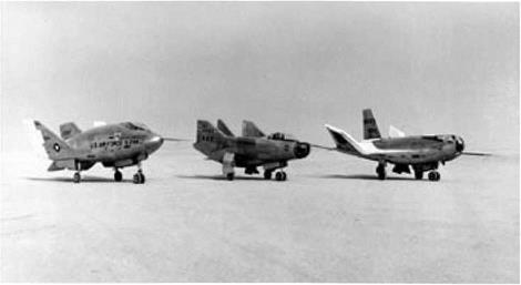
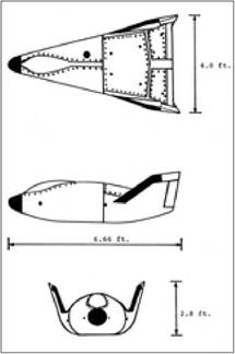
ASSET won approval as a program

late in January 1961. In April of that

year the firm of McDonnell Aircraft,

which was already building Mercury

capsules, won a contract to develop the

ASSET flight vehicles. Initial thought

had called for use of the solid-fuel Scout

as the booster. Soon, however, it became. . ,

АЬЬЫ, showing peak temperatures, clear that the program could use the (u. S. Air Force)

Thor for greater power. The Air Force

had deployed these missiles in England. When they came home, during 1963, they became available for use as launch vehicles.

ASSET took shape as a flat-bottomed wing-body craft that used the low-wing configuration recommended by NASA-Langley. It had a length of 59 inches and a span of 55 inches. Its bill of materials closely resembled that of Dyna-Soar, for it used TZM to withstand 3,000°F on the forward lower heat shield, graphite for similar temperatures on the leading edges, and zirconia rods for the nose cap, which was rated at 4,000°F. But ASSET avoided the use of Rene 4l, with cobalt and columbium alloys being employed instead.1

ASSET was built in two varieties: the Aerothermodynamic Structural Vehicle (ASV), weighing 1,130 pounds, and the Aerothermodynamic Elastic Vehicle (AEV), at 1,225 pounds. The AEVs were to study panel flutter along with the behavior of a trailing-edge flap, which represented an aerodynamic control surface in hypersonic flight. These vehicles did not demand the highest possible flight speeds and hence flew with single-stage Thors as the boosters. But the ASVs were built to study mate­rials and structures in the re-entry environment, while taking data on temperatures, pressures, and heat fluxes. Such missions demanded higher speeds. These boost – glide craft therefore used the two-stage Thor-Delta launch vehicle, which resembled
the Thor-Able that had conducted nose-cone tests at intercontinental range as early as 1958.2

The program conducted six flights, which had the following planned values of range and of altitude and velocity at release:

Asset Flight Tests

Date

Vehicle

Booster

Velocity,

feet/second

Altitude,

feet

Range,

nautical miles

18 September 1963

ASV-1

Thor

16,000

205,000

987

24 March 1964

ASV-2

Thor-Delta

18,000

195,000

1800

22 July 1964

ASV-3

Thor-Delta

19,500

225,000

1830

27 October 1964

AEV-1

Thor

13,000

168,000

830

8 December 1964

AEV-2

Thor

13,000

187,000

620

23 February 1965

ASV-4

Thor-Delta

19,500

206,000

2300

Source: Hallion, Hypersonic, pp. 505, 510-519.

Several of these craft were to be recovered. Following standard practice, their launches were scheduled for the early morning, to give downrange recovery crews the maximum hours of daylight. This did not help ASV-1, the first flight in the program, which sank into the sea. Still, it flew successfully and returned good data. In addition, this flight set a milestone. In the words of historian Richard Hallion, “for the first time in aerospace history, a lifting reentry spacecraft had successfully returned from space.”3

ASV-2 followed, using the two-stage Thor-Delta, but it failed when the second stage did not ignite. The next one carried ASV-3, with this mission scoring a double achievement. It not only made a good flight downrange but was successfully recov­ered. It carried a liquid-cooled double-wall test panel from Bell Aircraft, along with a molybdenum heat-shield panel from Boeing, home of Dyna-Soar. ASV-3 also had a new nose cap. The standard ASSET type used zirconia dowels, 1.5 inches long by 0.5 inch in diameter, that were bonded together with a zirconia cement. The new cap, from International Harvester, had a tungsten base covered with thorium oxide and was reinforced with tungsten.

A company advertisement stated that it withstood re-entry so well that it “could have been used again,” and this was true for the craft as a whole. Hallion writes that “overall, it was in excellent condition. Water damage…caused some problems, but not so serious that McDonnell could not have refurbished and reflown the vehicle.” The Boeing and Bell panels came through re-entry without damage, and the importance of physical recovery was emphasized when columbium aft leading edges showed significant deterioration. They were redesigned, with the new versions going into subsequent ASV and AEV spacecraft.4

The next two flights were AEVs, each of which carried a flutter test panel and a test flap. AEV-1 returned only one high-Mach data point, at Mach 11.88, but this sufficed to indicate that its panel was probably too stiff to undergo flutter. Engi­neers made it thinner and flew a new one on AEV-2, where it returned good data until it failed at Mach 10. The flap experiment also showed value. It had an elec­tric motor that deflected it into the airstream, with potentiometers measuring the force required to move it, and it enabled aerodynamicists to critique their theories. Thus, one treatment gave pressures that were in good agreement with observations, whereas another did not.

ASV-4, the final flight, returned “the highest quality data of the ASSET pro­gram,” according to the flight test report. The peak speed of 19,400 feet per second, Mach 18.4, was the highest in the series and was well above the design speed of

18,0 feet per second. The long hypersonic glide covered 2,300 nautical miles and prolonged the data return, which presented pressures at 29 locations on the vehicle and temperatures at 39. An onboard system transferred mercury ballast to trim the angle of attack, increasing L/D from its average of 1.2 to 1.4 and extending the trajectory. The only important problem came when the recovery parachute failed to deploy properly and ripped away, dooming ASV-4 to follow ASV-1 into the depths of the Atlantic.5

On the whole, ASSET nevertheless scored a host of successes. It showed that insulated hot structures could be built and flown without producing unpleasant surprises, at speeds up to three-fourths of orbital velocity. It dealt with such practical issues of design as fabrication, fasteners, and coatings. In hypersonic aerodynamics, ASSET contributed to understanding of flutter and of the use of movable con­trol surfaces. The program also developed and successfully used a reaction control system built for a lifting re-entry vehicle. Only one flight vehicle was recovered in four attempts, but it complemented the returned data by permitting a close look at a hot structure that had survived its trial by fire.

A separate prelude to the space shuttle took form during the 1960s as NASA and the Air Force pursued a burgeoning interest in lifting bodies. The initial con­cept represented one more legacy of the blunt-body principle of H. Julian Allen and Alfred Eggers at NACA’s Ames Aeronautical Laboratory. After developing this principle, they considered that a re-entering body, while remaining blunt to reduce its heat load, might produce lift and thus gain the ability to maneuver at hypersonic speeds. An early configuration, the M-l of 1957, featured a blunt-nosed cone with a flattened top. It showed some capacity for hypersonic maneuver but could not glide subsonically or land on a runway. A new shape, the M-2, appeared as a slender half-cone with its flat side up. Its hypersonic L/D of 1.4 was nearly triple that of the M-l. Fitted with two large vertical fins for stability, it emerged as a basic configura­tion that was suitable for further research.6

Dale Reed, an engineer at NASA’s Flight Research Center, developed a strong interest in the bathtub-like shape of the M-2. He was a sailplane enthusiast and a builder of radio-controlled model aircraft. With support from the local community of airplane model builders, he proceeded to craft the M-2 as a piloted glider. Desig­nating it as the M2-F1, he built it of plywood over a tubular steel frame. Completed early in 1963, it was 20 feet long and 13 feet across.

It needed a vehicle that could tow it into the air for initial tests. However, it produced too much drag for NASA’s usual vans and trucks, and Reed needed a tow car with more power. He and his friends bought a stripped-down Pontiac with a big engine and a four-barrel carburetor that reached speeds of 110 miles per hour. They took it to a funny-car shop in Long Beach for modification. Like any other flightline vehicle, it was painted yellow with “National Aeronautics and Space Administra­tion” on its side. Early tow tests showed enough success to allow the project to use a C-47, called the Cooney Bird, for true aerial flights. During these tests the Cooney Bird towed the M2-F1 above 10,000 feet and then set it loose to glide to an Edwards AFB lakebed. Beginning in August 1963, the test pilot Milt Thompson did this repeatedly. Reed thus showed that although the basic M-2 shape had been crafted for hypersonic re-entry, it could glide to a safe landing.

As he pursued this work, he won support from Paul Bikle, the director of NASA Flight Research Center. As early as April 1963, Bikle alerted NASA Headquarters that “the lifting-body concept looks even better to us as we get more into it.” The success of the M2-F1 sparked interest within the Air Force as well. Some of its offi­cials, along with their NASA counterparts, went on to pursue lifting-body programs that called for more than plywood and funny cars. An initial effort went beyond the M2-F1 by broadening the range of lifting-body shapes while working to develop satisfactory landing qualities.7

NASA contracted with the firm of Northrop to build two such aircraft: the M2- F2 and HL-10. The M2-F2 amounted to an M2-F1 built to NASA standards; the HL-10 drew on an alternate lifting-body design by Eugene Love of NASA-Langley. This meant that both Langley and Ames now had a project. The Air Force effort, the X-24A, went to the Martin Company. It used a design of Frederick Raymes at the Aerospace Corporation that resembled a teardrop fitted with two large fins.

All three flew initially as gliders, with a B-52 rather than a C-47 as the mother ship. The lifting bodies mounted small rocket engines for acceleration to supersonic

speeds, thereby enabling tests of stability and handling qualities in transonic flight. The HL-10 set records for lifting bodies by making safe approaches and landings at Edwards from speeds up to Mach 1.86 and altitudes of 90,000 feet.8

Acceptable handling qualities were not easy to achieve. Under the best of cir­cumstances, a lifting body flew like a brick at low speeds. Lowering the landing gear made the problem worse by adding drag, and test pilots delayed this deployment as long as possible. In May 1967 the pilot Bruce Peterson, flying the M2-F2, failed to get his gear down in time. The aircraft hit the lakebed at more than 250 mph, rolled over six times, and then came to rest on its back minus its cockpit canopy, main landing gear, and right vertical fin. Peterson, who might have died in the crash, got away with a skull fracture, a mangled face, and the loss of an eye. While surgeons reconstructed his face and returned him to active duty, the M2-F2 underwent sur­gery as well. Back at Northrop, engineers installed a center fin and a roll-control system that used reaction jets, while redistributing the internal weights. Gerauld Gentry, an Air Force test pilot, said that these changes turned “something I really did not enjoy flying at all into something that was quite pleasant to fly.”9

The manned lifting-body program sought to turn these hypersonic shapes into aircraft that could land on runways, but the Air Force was not about to overlook the need for tests of their hypersonic performance during re-entry. The program that addressed this issue took shape with the name PRIME, Precision Recovery Includ­ing Maneuvering Entry. Martin Marietta, builder of the X-24A, also developed the PRIME flight vehicle, the SV-5D that later was referred to as the X-23- Although it was only seven feet in length, it faithfully duplicated the shape of the X-24A, even including a small bubble-like protrusion near the front that represented the cockpit canopy.

PRIME complemented ASSET, with both programs conducting flight tests of boost-glide vehicles. However, while ASSET pushed the state of the art in materials and hot structures, PRIME used ablative thermal protection for a more straightfor­ward design and emphasized flight performance. Accelerated to near-orbital veloci­ties by Atlas launch vehicles, the PRIME missions called for boost-glide flight from Vandenberg AFB to locations in the western Pacific near Kwajalein Atoll. The SV – 5D had higher L/D than Gemini or Apollo, and as with those NASA programs, it was to demonstrate precision re-entry. The plans called for crossrange, with the vehicle flying up to 710 nautical miles to the side of a ballistic trajectory and then arriving within 10 miles of its recovery point.10

The X-24A was built of aluminum. The SV-5D used this material as well, for both the skin and primary structure. It mounted both aerodynamic and reaction controls, with the former taking shape as right and left body-mounted flaps set well aft. Used together, they controlled pitch; used individually, they produced yaw and roll. These flaps were beryllium plates that provided thermal heat sink. The fins were of steel honeycomb with surfaces of beryllium sheet.

Preludes: Asset and Lifting Bodies

Lifting bodies. Left to right: the X-24A, the M2-F3 which was modified from the M2-F2, and the HL-10. (NASA)


Preludes: Asset and Lifting Bodies

Landing a lifting body. The wingless X-24B required a particularly high angle of attack. (NASA)


Preludes: Asset and Lifting BodiesPreludes: Asset and Lifting Bodies

Martin SV-5D, which became the X-23. Mission of the SV-5D. (U. S. Air Force)

Подпись: ЙЗ rfp да Mt ,'K1 fW JW ^ jptf О? да

(U. S. Air Force)

Trajectory of the SV-5D, showing crossrange. (U. S. Air Force)

Most of the vehicle surface obtained thermal protection from ESA 3560 HF, a flexible ablative blanket of phenolic fiberglass honeycomb that used a silicone elas­tomer as the filler, with fibers of nylon and silica holding the ablative char in place during re-entry. ESA 5500 HE a high-density form of this ablator, gave added pro­tection in hotter areas. The nose cap and the beryllium flaps used a different mate­rial: a carbon-phenolic composite. At the nose, its thickness reached 3-5 inches.11

The PRIME program made three flights, which took place between December 1966 and April 1967. All returned data successfully, with the third flight vehicle also being recovered. The first mission reached 25,300 feet per second and flew 4,300 miles downrange, missing its target by only 900 feet. The vehicle executed pitch maneuvers but made no attempt at crossrange. The next two flights indeed achieved crossrange, of 500 and 800 nautical miles, and the precision again was impressive. Flight 2 missed its aim point by less than two miles. Flight 3 missed by more than four miles, but this still was within the allowed limit. Moreover, the terminal guid­ance radar had been inoperative, which probably contributed to the lack of absolute accuracy.12

By demonstrating both crossrange and high accuracy during maneuvering entry, PRIME broadened the range of hypersonic aircraft configurations and completed a line of development that dated to 1953- In December of that year the test pilot Chuck Yeager had nearly been killed when his X-1A fell out of the sky at Mach 2.44 because it lacked tail surfaces that could produce aerodynamic stability. The X-l 5 was to fly to Mach 6, and Charles McLellan of NACA-Langley showed that it could use vertical fins of reasonable size if they were wedge-shaped in cross section. Meanwhile, Allen and Eggers were introducing their blunt-body principle. This led to missile nose cones with rounded tips, designed both as cones and as blunted cylinders that had stabilizing afterbodies in the shape of conic frustums.

For manned flight, Langleys Maxime Faget introduced the general shape of a cone with its base forward, protected by an ablative heat shield. Langleys John Becker entered the realm of winged re-entry configurations with his low-wing flat-bottom shapes that showed advantage over the high-wing flat-top concepts of NACA-Ames. The advent of the lifting body then raised the prospect of a struc­turally efficient shape that lacked wings, demanded thermal protection and added weight, and yet could land on a runway. Faget’s designs had found application in Mercury, Gemini, and Apollo, while Becker’s winged vehicle had provided a basis for Dyna-Soar. As NASA looked to the future, both winged designs and lifting bodies were in the forefront.13

Hypersonics and the Aviation Frontier

Aviation has grown through reliance upon engines, and three types have been important: the piston motor, turbojet, and rocket. Hypersonic technologies have made their largest contributions, not by adding the scramjet to this list, but by enhancing the value and usefulness of rockets. This happened when these technolo­gies solved the re-entry problem.

This problem addressed critical issues of the national interest, for it was essential to the success of Corona and of the return of film-carrying capsules from orbit. It also was a vital aspect of the development of strategic missiles. Still, if such weapons had proven to be technically infeasible, the superpowers would have fallen back on their long-range bombers. No such backup was available within the Corona program. During the mid-1960s the Lunar Orbiter Program used a high-resolution system for scanning photographic film, with the data being returned using telem­etry.88 But this arrangement had a rather slow data rate and was unsuitable for the demands of strategic reconnaissance.

Success in re-entry also undergirded the piloted space program. In 40 years of effort, this program has failed to find a role in the mainstream of technical activity akin to the importance of automated satellites in telecommunications. Still, piloted flight brought the unforgettable achievements of Apollo, which grow warmer in memory as the decades pass.

In a related area, the advent of thermal-protection methods led to the develop­ment of aircraft that burst all bounds on speed and altitude. These took form as the X-15 and the space shuttle. On the whole, though, this work has led to disappoint­ment. The Air Force had anticipated that airbreathing counterparts of the X-15, powered perhaps by ramjets, would come along in the relatively near future. This did not happen; the X-15 remains sui generis, a thing unto itself. In turn, the shuttle failed to compete effectively with expendable launch vehicles.

This conclusion remains valid in the wake of the highly publicized flights of SpaceShipOne, built by the independent inventor Burt Rutan. Rutan showed an uncanny talent for innovation in 1986, when his Voyager aircraft, piloted by his brother Dick and by Dicks former girlfriend Jeana Yeager, circled the world on a single load of fuel. This achievement had not even been imagined, for no science – fiction writer had envisioned such a nonstop flight around the world. What made it possible was the use of composites in construction. Indeed, Voyager was built at

Rutan’s firm of Scaled Composites.89 Such lightweight materials also found use in the construction of SpaceShipOne, which was assembled within that plant.

SpaceShipOne brought the prospect of routine commercial flights having the performance of the X-15. Built entirely as a privately funded venture, it used a simple rocket engine that burned rubber, with nitrous oxide as the oxidizer, and reached altitudes as high as 70 miles. A movable set of wings and tail booms, rotat­ing upward, provided stability in attitude during re-entry and kept the crafts nose pointing upward as well. The craft then glided to a landing.

There was no commercial follow-on to Voyager, but today there is serious inter­est in building commercial versions of SpaceShipOne that will take tourists on brief hops into space—and enable them to win astronauts’ wings in the process. Rich­ard Branson, founder of Virgin Airways, is currently sponsoring a new enterprise, Virgin Galactic, that aims to do just that. He has formed a partnership with Scaled, has sold more than 100 tickets at $200,000 each, and hopes for his first flight late in 2008.

And yet__ The top speed of SpaceShipOne was only 2,200 miles per hour, or

Mach 3-3. Rutans vehicle thus stands today as a brilliant exercise in rocketry and the design of reusable piloted spacecraft. But it is too slow to qualify as a project in hypersonics.90

Is that it, then? Following more than half a century of effort, does the re-entry problem stand as the single unambiguous contribution of hypersonics? Air Force historian Richard Hallion has written of a “hypersonic revolution,” but from this perspective, one may regard hypersonics less as an extension of aeronautics than as a branch of materials science, akin to metallurgy. Specialists in that field introduced superalloys that extended the temperature limits of jet engines, thereby enhanc­ing their range and fuel economy. Similarly, the hypersonics community developed lightweight thermal-protection systems that have found use even in exploring the planet Jupiter. Yet one does not speak of a “superalloy revolution,” and hypersonics has had similarly limited application.

There remains the issue of the continuing effort to develop the scramjet. This work has gone forward as part of an ongoing hope that better methods might be devised for ascent to orbit, corresponding perhaps to the jet airliners that drove their piston-driven counterparts to the boneyard. Access to space holds undeniable importance, and one may speak without challenge of a “satellite revolution” when we consider the vital role of such craft in a host of areas: weather forecasting, naviga­tion, tactical warfare, reconnaissance, as well as telecommunications. Yet low-cost access remains out of reach and hence continues to justify work on advanced tech­nologies, including scramjets.

Still, despite 40 years of effort, the scramjet continues to stand at two removes from importance. The first goal is simply to make it work, by demonstrating flight to orbit in a vehicle that uses such engines for propulsion. The X-30 was to fly in

this fashion, although present-day thinking leans more toward using it merely in an airbreathing first stage. But at least within the next decade the most that anyone hopes for is to accelerate a small test vehicle of the X-43 class.91

Yet even if a large launch vehicle indeed should fly using scramjets, it then will face a subsequent test, for it will have to win success in the face of competition from existing launchers. The history of aerospace shows several types of craft that indeed flew well but that failed in the market. The classic example was the dirigible, which was abandoned because it could not be made safe.92

The world still remembers the Hindenburg, but the problems ran deeper than the use of hydrogen. Even with nonflammable helium, such airships proved to be structurally weak. The U. S. Navy built three large ones—the Shenandoah, Akron, and Macon—and quickly lost them all in storms and severe weather. Nor has this problem been solved. Dirigibles might be attractive today as aerial cruise ships, offering unparalleled views of Caribbean islands, but the safety problem persists.

More recently the Concorde supersonic airliner flew with great style and panache but faltered due to its high costs. The Saturn V Moon rocket proved to be too large to justify continued production; it lacked payloads that demanded its heft. Piloted space flight raises its own questions. It too is very costly, and in the light of experi­ence with the shuttle, perhaps it too cannot be made completely safe.

Yet though scramjets face obstacles both in technology and in the market, they will continue to tantalize. Hallion writes that faith in a future for hypersonics “is akin to belief in the Second Coming: one knows and trusts that it will occur, but one can’t be certain when.” Scramjet advocates will continue to echo the defiant words of Eugen Sanger: “Nevertheless, my silver birds will fly!”93

[1]Official flight records are certified by the Federation Aeronautique Internationale. The cited accomplishments lacked this distinction, but they nevertheless represented genuine achievements.

Origins of the x-15

Experimental aircraft flourished during the postwar years, but it was hard for them to keep pace with the best jet fighters. The X-l, for instance, was the first piloted aircraft to break the sound barrier. But only six months later, in April 1948, the test pilot George Welch did this in a fighter plane, the XP-86.3 The layout of the XP-86 was more advanced, for it used a swept wing whereas the X-l used a simple straight wing. Moreover, while the X-l was a highly specialized research airplane, the XP-86 was a prototype of an operational fighter.

Much the same happened at Mach 2. The test pilot Scott Crossfield was the first to reach this mark, flying the experimental Douglas Skyrocket in November 1953.4 Just then, Alexander Kartveli of Republic Aviation was well along in crafting the XF-105. The Air Force had ordered 37 of them in March 1953- It first flew in December 1955; in June 1956 an F-105 reached Mach 2.15. It too was an opera­tional fighter, in contrast to the Skyrocket of two and a half years earlier.

Ramjet-powered craft were to do even better. Navaho was to fly near Mach 3- An even more far-reaching prospect was in view at that same Republic Aviation, where Kartveli was working on the XF-103. It was to fly at Mach 3-7 with its own ramjet, nearly 2,500 miles per hour (mph), with a sustained ceiling of 75,000 feet.5

Yet it was already clear that such aircraft were to go forward in their programs without benefit of research aircraft that could lay groundwork. The Bell X-2 was in development as a rocket plane designed to reach Mach 3, but although first thoughts of it dated to 1945, the program encountered serious delays. The airplane did not so much as fly past Mach 1 until 1956.6

Hence in 1951 and 1952, it already was too late to initiate a new program aimed at building an X-plane that could provide timely support for the Navaho and XF – 103- The X-10 supported Navaho from 1954 to 1957, but it used turbojets rather than ramjets and flew at Mach 2.There was no quick and easy way to build aircraft capable of Mach 3, let alone Mach 4; the lagging X-2 was the only airplane that might do this, however belatedly Yet it was already appropriate to look beyond the coming Mach 3 generation and to envision putative successors.

Maxwell Hunter, at Douglas Aircraft, argued that with fighter aircraft on their way to Mach 3, antiaircraft missiles would have to fly at Mach 5 to Mach 10/ In addition, Walter Dornberger, the wartime head of Germany’s rocket program, now was at Bell Aircraft. He was directing studies of Bomi, Bomber Missile, a two – stage fully reusable rocket-powered bomber concept that was to reach 8,450 mph, or Mach 12.8 At Convair, studies of intercontinental missiles included boost-glide concepts with much higher speeds.9 William Dorrance, a company aerodynamicist, had not been free to disclose the classified Atlas concept to NACA but nevertheless declared that data at speeds up to Mach 20 were urgently needed.10 In addition, the Rand Corporation had already published reports that envisioned spacecraft in orbit. The documents proposed that such satellites could serve for weather observation and for military reconnaissance.11

At Bell Aircraft, Robert Woods, a co-founder of the company, took a strong interest in Dornberger’s ideas. Woods had designed the X-l, the X-1A that reached Mach 2.4, and the X-2. He also was a member ofNACAs influential Committee on Aerodynamics. At a meeting of this committee in October 1951, he recommended a feasibility study of a “V-2 research airplane, the objective of which would be to obtain data at extreme altitudes and speeds and to explore the problems of re-entry into the atmosphere.”12 He reiterated this recommendation in a letter to the com­mittee in January 1952. Later that month, he received a memo from Dornberger that outlined an “ionospheric research plane,” capable of reaching altitudes of “more than 75 miles.”13

NACA Headquarters sent copies of these documents to its field centers. This brought responses during May, as several investigators suggested means to enhance the performance of the X-2. The proposals included a rocket-powered carrier air­craft with which this research airplane was to attain “Mach numbers up to almost 10 and an altitude of about 1,000,000 feet,”14 which the X-2 had certainly never been meant to attain. A slightly more practical concept called for flight to 300,000 feet.15 These thoughts were out in the wild blue, but they showed that people at least were ready to think about hypersonic flight.

Accordingly, at a meeting in June 1952, the Committee on Aerodynamics adopted a resolution largely in a form written by another of its members, the Air Force science advisor Albert Lombard:

WHEREAS, The upper stratosphere is the important new flight region for military aircraft in the next decade and certain guided missiles are already under development to fly in the lower portions of this region, and WHEREAS, Flight in the ionosphere and in satellite orbits in outer space has long-term attractiveness to military operations—

RESOLVED, That the NACA Committee on Aerodynamics recommends that (1) the NACA increase its program dealing with problems of unmanned and manned flight in the upper stratosphere at altitudes between 12 and 50 miles, and at Mach numbers between 4 and 10, and (2) the NACA devote a modest effort to problems associated with unmanned and manned flights at altitudes from 50 miles to infinity and at speeds from Mach number 10 to the velocity of escape from the Earth’s gravity.

Three weeks later, in mid-July, the NACA Executive Committee adopted essen­tially the same resolution, thus giving it the force of policy.16

Floyd Thompson, associate director of NACA-Langley, responded by setting up a three-man study team. Their report came out a year later. It showed strong fascina­tion with boost-glide flight, going so far as to propose a commercial aircraft based on a boost-glide Atlas concept that was to match the standard fares of current airliners. On the more immediate matter of a high-speed research airplane, this group took the concept of a boosted X-2 as a point of departure, suggesting that such a vehicle could reach Mach 3-7. Like the million-foot X-2 and the 300,000-foot X-2, this lay beyond its thermal limits. Still, this study pointed clearly toward an uprated X-2 as the next step.17

The Air Force weighed in with its views in October 1953. A report from the Aircraft Panel of its Scientific Advisory Board (SAB) discussed the need for a new research airplane of very high performance. The panelists stated that “the time was ripe” for such a venture and that its feasibility “should be looked into.”18 With this plus the report of the Langley group, the question of such a research plane went on the agenda of the next meeting of NACA’s Interlaboratory Research Airplane Panel. It took place at NACA Headquarters in Washington in February 1954.

It lasted two days. Most discussions centered on current programs, but the issue of a new research plane indeed came up. The participants rejected the concept of an uprated X-2, declaring that it would be too small for use in high-speed studies. They concluded instead “that provision of an entirely new research airplane is desir­able.”19

This decision led quickly to a new round of feasibility studies at each of the four NACA centers: Langley, Ames, Lewis, and the High-Speed Flight Station. The study conducted at Langley was particularly detailed and furnished much of the basis for the eventual design of the X-15- Becker directed the work, taking respon­sibility for trajectories and aerodynamic heating. Maxime Faget addressed issues of propulsion. Three other specialists covered the topics of structures and materials, piloting, configuration, stability, and control.20

A performance analysis defined a loaded weight of 30,000 pounds. Heavier weights did not increase the peak speed by much, whereas smaller concepts showed a marked falloff in this speed. Trajectory studies then showed that this vehicle could reach a range of speeds, from Mach 5 when taking off from the ground to Mach 10 if launched atop a rocket-powered first stage. If dropped from a B-52 carrier, it would attain Mach 6.3.21

Concurrently with this work, prompted by a statement written by Langleys Robert Gilruth, the Air Force’s Aircraft Panel recommended initiation of a research airplane that would reach Mach 5 to 7, along with altitudes of several hundred thou­sand feet. Beckers group selected a goal of Mach 7, noting that this would permit investigation of “extremely wide ranges of operating and heating conditions.” By contrast, a Mach 10 vehicle “would require a much greater expenditure of time and effort” and yet “would add little in the fields of stability, control, piloting problems, and structural heating.”22

A survey of temperature-resistant superalloys brought selection of Inconel X for the primary aircraft structure. This was a proprietary alloy from the firm of Inter­national Nickel, comprising 72.5 percent nickel, 15 percent chromium, 1 percent columbium, and iron as most of the balance. Its principal constituents all counted among the most critical materials used in aircraft construction, being employed in small quantities for turbine blades in jet engines. But Inconel X was unmatched in temperature resistance, holding most of its strength and stiffness at temperatures as high as 1200°F.23

Could a Mach 7 vehicle re-enter the atmosphere without exceeding this tem­perature limit? Becker’s designers initially considered that during reentry, the air­plane should point its nose in the direction of flight. This proved impossible; in Becker’s words, “the dynamic pressures quickly exceeded by large margins the limit of 1,000 pounds per square foot set by structural considerations, and the heating loads became disastrous.”

Becker tried to alleviate these problems by using lift during re-entry. According to his calculations, he obtained more lift by raising the nose—and the problem became far more manageable. He saw that the solution lay in having the plane enter the atmosphere with its nose high, presenting its flat undersurface to the air. It then would lose speed in the upper atmosphere, easing both the overheating and the aerodynamic pressure. The Allen-Eggers paper had been in print for nearly a year, and in Becker’s words, “it became obvious to us that what we were seeing here was a new manifestation of H. J. Allen’s ‘blunt-body’ principle. As we increased the angle of attack, our configuration in effect became more ‘blunt.’” Allen and Eggers had

Origins of the x-15

X-15 skin gauges and design temperatures. Generally, the heaviest gauges were required to meet the most severe temperatures. (NASA)

developed their principle for missile nose cones, but it now proved equally useful when applied to a hypersonic airplane.24

The use of this principle now placed a structural design concept within reach. To address this topic, Norris Dow, the structural analyst, considered the use of a heat-sink structure. This was to use Inconel X skin of heavy gauge to absorb the heat and spread it through this metal so as to lower its temperature. In addition, the skin was to play a structural role. Like other all-metal aircraft, the nascent X-15 was to use stressed-skin construction. This gave the skin an optimized thickness so that it could carry part of the aerodynamic loads, thus reducing the structural weight.

Dow carried through a design exercise in which he initially ignored the issue of heating, laying out a stressed-skin concept built of Inconel X with skin gauges deter­mined only by requirements of mechanical strength and stiffness. A second analysis then took note of the heating, calculating new gauges that would allow the skin to serve as a heat sink. It was clear that if those gauges were large, adding weight to the airplane, then it might be necessary to back off from the Mach 7 goal so as to reduce the input heat load, thereby reducing the required thicknesses.

When Dow made the calculations, he received a welcome surprise. He found that the weight and thickness of a heat-absorbing structure were nearly the same as those of a simple aerodynamic structure! This meant that a hypersonic airplane, designed largely from consideration of aerodynamic loads, could provide heat-sink thermal protection as a bonus. It could do this with little or no additional weight.25

This, more than anything, was the insight that made the X-15 possible. Design­ers such as Dow knew all too well that ordinary aircraft aluminum lost strength beyond Mach 2, due to aerodynamic heating. Yet if hypersonic flight was to mean anything, it meant choosing a goal such as Mach 7 and then reaching this goal through the clever use of available heat-resistant materials. In Becker’s study, the Allen-Eggers blunt-body principle reduced the re-entry heating to a level that Inco­nel X could accommodate.

The putative airplane still faced difficult issues of stability and control. Early in 1954 these topics were in the forefront, for the test pilot Chuck Yeager had nearly crashed when his X-1A fell out of the sky due to a loss of control at Mach 2.44. This problem of high-speed instability reflected the natural instability, at all Mach num­bers, of a simple wing-body vehicle that lacked tail surfaces. Such surfaces worked well at moderate speeds, like the feathers of an arrow, but lost effectiveness with increasing Mach. Yeager’s near-disaster had occurred because he had pushed just beyond a speed limit set by such considerations of stability. These considerations would be far more severe at Mach 7-26

Another Langley aerodynamicist, Charles McLellan, took up this issue by closely examining the airflow around a tail surface at high Mach. He drew on recent experi­mental results from the Langley 11-inch hypersonic tunnel, involving an airfoil with a cross section in the shape of a thin diamond. Analysis had indicated that most of the control effectiveness of this airfoil was generated by its forward wedge-shaped portion. The aft portion contributed little to its overall effectiveness because the pres­sures on that part of the surface were lower. Experimental tests had confirmed this.

McLellan now proposed to respond to the problem of hypersonic stability by using tail surfaces having airfoils that would be wedge-shaped along their entire length. In effect, such a surface would consist of a forward portion extending all the way to the rear. Subsequent tests in the 11-inch tunnel confirmed that this solution worked. Using standard thin airfoils, the new research plane would have needed tail surfaces nearly as large as the wings. The wedge shape, which saw use in the opera­tional X-15, reduced their sizes to those of conventional tails.27

The groups report, dated April 1954, contemplated flight to altitudes as great as 350,000 feet, or 66 miles. (The X-15 went to 354,200 feet in 1963-)28This was well above the sensible atmosphere, well into an altitude range where flight would be bal­listic. This meant that at that early date, Becker’s study was proposing to accomplish piloted flight into space.

Reusable Surface Insulation

As PRIME and the lifting bodies broadened the choices of hypersonic shape, work at Lockheed made similar contributions in the field of thermal protection. Ablatives were unrivaled for once-only use, but during the 1960s the hot structure continued to stand out as the preferred approach for reusable craft such as Dyna – Soar. As noted, it used an insulated primary or load-bearing structure with a skin of outer panels. These emitted heat by radiation, maintaining a temperature that was high but steady. Metal fittings supported these panels, and while the insulation could be high in quality, these fittings unavoidably leaked heat to the underlying structure. This raised difficulties in crafting this structure of aluminum or even of titanium, which had greater heat resistance. On Dyna-Soar, only Rene 41 would do.14

Ablatives avoided such heat leaks, while being sufficiently capable as insulators to permit the use of aluminum, as on the SV-5D of PRIME. In principle, a third approach combined the best features of hot structure and ablatives. It called for the use of temperature-resistant tiles, made perhaps of ceramic, that could cover the vehicle skin. Like hot-structure panels, they would radiate heat while remaining cool enough to avoid thermal damage. In addition, they were to be reusable. They also were to offer the excellent insulating properties of good ablators, preventing heat from reaching the underlying structure—which once more might be of alumi­num. This concept, known as reusable surface insulation (RSI), gave rise in time to the thermal protection of the shuttle.

RSI grew out of ongoing work with ceramics for thermal protection. Ceramics had excellent temperature resistance, light weight, and good insulating properties. But they were brittle, and they cracked rather than stretched in response to the flex­ing under load of an underlying metal primary structure. Ceramics also were sensi­tive to thermal shock, as when heated glass breaks when plunged into cold water. This thermal shock resulted from rapid temperature changes during re-entry.15

Monolithic blocks of the ceramic zirconia had been specified for the nose cap of Dyna-Soar, but a different point of departure used mats of ceramic fiber in lieu of the solid blocks. The background to the shuttles tiles lay in work with such mats that dated to the early 1960s at Lockheed Missiles and Space Company. Key people included R. M. Beasley, Ronald Banas, Douglas Izu, and Wilson Schramm. A Lock­heed patent disclosure of December I960 gave the first presentation of a reusable insulation made of ceramic fibers for use as a heat shield. Initial research dealt with casting fibrous layers from a slurry and bonding the fibers together.

Related work involved filament-wound structures that used long continuous strands. Silica fibers showed promise and led to an early success: a conical radome of 32-inch diameter built for Apollo in 1962. Designed for re-entry, it had a filament – wound external shell and a lightweight layer of internal insulation cast from short fibers of silica. The two sections were densified with a colloid of silica particles and
sintered into a composite. This resulted in a non-ablative structure of silica compos­ite, reinforced with fiber. It never flew, as design requirements changed during the development of Apollo. Even so, it introduced silica fiber into the realm of re-entry design.

Another early research effort, Lockheat, fabricated test versions of fibrous mats that had controlled porosity and microstructure. These were impregnated with organic fillers such as Plexiglas (methyl methacrylate). These composites resembled ablative materials, although the filler did not char. Instead it evaporated or volatil­ized, producing an outward flow of cool gas that protected the heat shield at high heat-transfer rates. The Lockheat studies investigated a range of fibers that included silica, alumina, and boria. Researchers constructed multilayer composite structures of filament-wound and short-fiber materials that resembled the Apollo radome. Impregnated densities were 40 to 60 pounds per cubic foot, the higher number being close to the density of water. Thicknesses of no more than an inch resulted in acceptably low back-face temperatures during simulations of re-entry.

This work with silica-fiber ceramics was well under way during 1962. Three years later a specific formulation of bonded silica fibers was ready for further develop­ment. Known as LI-1500, it was 89 percent porous and had a density of 15 pounds per cubic foot, one-fourth that of water. Its external surface was impregnated with filler to a predetermined depth, again to provide additional protection during the most severe re-entry heating. By the time this filler was depleted, the heat shield was to have entered a zone of more moderate heating, where the fibrous insulation alone could provide protection.

Initial versions of LI-1500, with impregnant, were intended for use with small space vehicles, similar to Dyna-Soar, that had high heating rates. Space shuttle con­cepts were already attracting attention—the January 1964 issue of the trade journal Astronautics & Aeronautics presents the thinking of the day—and in 1965 a Lock­heed specialist, Max Hunter, introduced an influential configuration called Star Clipper. His design called for LI-1500 as the thermal protection.

Like other shuttle concepts, Star Clipper was to fly repeatedly, but the need for

Reusable Surface Insulationan impregnant in LI-1500 compromised its reusabil­ity. In contrast to earlier entry vehicle concepts, Star Clipper was large, offering exposed surfaces that were sufficiently blunt to benefit from the Allen-Eggers prin­ciple. They had lower tem­peratures and heating rates,

Star Clipper concept. (Art by Dan Gautier)
which made it possible to dispense with the impregnant. An unfilled version of LI-1500, which was inherently reusable, now could serve.

Here was the first concept of a flight vehicle with reusable insulation, bonded to the skin, that could reradiate heat in the fashion of a hot structure. However, the matted silica by itself was white and had low thermal emissivity, making it a poor radiator of heat. This brought excessive surface temperatures that called for thick layers of the silica insulation, adding weight. To reduce the temperatures and the thickness, the silica needed a coating that could turn it black, for high emissivity. It then would radiate well and remain cooler.

The selected coating was a borosilicate glass, initially with an admixture of chro­mium oxide and later with silicon carbide, which further raised the emissivity. The glass coating and silica substrate were both silicon dioxide; this assured a match of their coefficients of thermal expansion, to prevent the coating from developing cracks under the temperature changes of re-entry. The glass coating could soften at very high temperatures to heal minor nicks or scratches. It also offered true reusabil­ity, surviving repeated cycles to 2,500°F. A flight test came in 1968, as NASA-Lang – ley investigators mounted a panel of LI-1500 to a Pacemaker re-entry test vehicle, along with several candidate ablators. This vehicle carried instruments, and it was recovered. Its trajectory reproduced the peak heating rates and temperatures of a re­entering Star Clipper. The LI-1500 test panel reached 2,300°F and did not crack, melt, or shrink. This proof-of-concept test gave further support to the concept of high-emittance reradiative tiles of coated silica for thermal protection.16

Lockheed conducted further studies at its Palo Alto Research Center. Investiga­tors cut the weight of RSI by raising its porosity from the 89 percent of LI-1500 to 93 percent. The material that resulted, LI-900, weighed only nine pounds per cubic foot, one-seventh the density of water.17 There also was much fundamental work on materials. Silica exists in three crystalline forms: quartz, cristobalite, tridymite. These not only have high coefficients of thermal expansion but also show sudden expansion or contraction with temperature due to solid-state phase changes. Cris­tobalite is particularly noteworthy; above 400°F it expands by more than 1 percent as it transforms from one phase to another. Silica fibers for RSI were to be glass, an amorphous rather than crystalline state having a very low coefficient of thermal expansion and absence of phase changes. The glassy form thus offered superb resis­tance to thermal stress and thermal shock, which would recur repeatedly during each return from orbit.18

The raw silica fiber came from Johns-Manville, which produced it from high – purity sand. At elevated temperatures it tended to undergo “devitrification,” trans­forming from a glass into a crystalline state. Then, when cooling, it passed through phase-change temperatures and the fiber suddenly shrank, producing large internal tensile stresses. Some fibers broke, giving rise to internal cracking within the RSI and degradation of its properties. These problems threatened to grow worse during subsequent cycles of re-entry heating.

To prevent devitrification, Lockheed worked to remove impurities from the raw fiber. Company specialists raised the purity of the silica to 99-9 percent while reduc­ing contaminating alkalis to as low as six parts per million. Lockheed did these things not only at the laboratory level but also in a pilot plant. This plant took the silica from raw material to finished tile, applying 140 process controls along the way. Established in 1970, the pilot plant was expanded in 1971 to attain a true manufacturing capability. Within this facility, Lockheed produced tiles of LI-1500 and LI-900 for use in extensive programs of test and evaluation. In turn, the increas­ing availability of these tiles encouraged their selection for shuttle thermal protec­tion, in lieu of a hot-structure approach.19

General Electric also became actively involved, studying types of RSI made from zirconia and from mullite, as well as from silica. The raw fibers were commercial grade, with the zirconia coming from Union Carbide and the mullite from Babcock and Wilcox. Devitrification was a problem, but whereas Lockheed had addressed it by purifying its fiber, GE took the raw silica from Johns-Manville and tried to use it with little change. The basic fiber, the Q-felt of Dyna-Soar, also had served as insulation on the X-15. It contained 19 different elements as impurities. Some were present at a few parts per million, but others—aluminum, calcium, copper, lead, magnesium, potassium, sodium—ran from 100 to 1000 parts per million. In total, up to 0.3 percent was impurity. General Electric treated this fiber with a silicone resin that served as a binder, pyrolyzing the resin and causing it to break down at high temperatures. This transformed the fiber into a composite, sheath­ing each strand with a layer of amorphous silica that had a purity of 99-98 percent and higher. This high purity resulted from that of the resin. The amorphous silica bound the fibers together while inhibiting their devitrification. General Electrics RSI had a density of 11.5 pounds per cubic foot, midway between that of LI-900 and LI-1500.20

In January 1972, President Richard Nixon gave his approval to the space shuttle program, thereby raising it to the level of a presidential initiative. Within days, NASA’s Dale Myers spoke to a lunar science conference in Houston and stated that the agency had made the basic decision to use RSI. Requests for proposal soon went out, inviting leading aerospace corporations to bid for the prime contract on the shuttle orbiter, and North American won this $2.б-billion prize in July. It specified mullite RSI for the undersurface and forward fuselage, a design feature that had been held over from the fully-reusable orbiter of the previous year.

Most of the primary structure was aluminum, but that of the nose was titanium, with insulation of zirconia lining the nose cap. The wing and fuselage upper sur­faces, which had been titanium hot structure, now went over to an elastomeric RSI consisting of a foamed methylphenyl silicone, bonded to the orbiter in panel sizes as large as 36 inches. This RSI gave protection to 650°F.21

Still, was mullite RSI truly the one to choose? It came from General Electric and had lower emissivity than the silica RSI of Lockheed but could withstand higher temperatures. Yet the true basis for selection lay in the ability to withstand a hun­dred re-entries, as simulated in ground test. NASA conducted these tests during the last five months of 1972, using facilities at its Ames, Johnson, and Kennedy centers, with support from Battelle Memorial Institute.

The main series of tests ran from August to November and gave a clear advantage to Lockheed. That firm’s LI-900 and LI-1500 went through 100 cycles to 2,300°F and met specified requirements for maintenance of low back-face temperatures and minimal thermal conductivity. The mullite showed excessive back-face tempera­tures and higher thermal conductivity, particularly at elevated temperatures. As test conditions increased in severity, the mullite also developed coating cracks and gave indications of substrate failure.

The tests then introduced acoustic loads, with each cycle of the simulation now subjecting the RSI to loud roars of rocket flight along with the heating of re-entry. LI-1500 continued to show promise. By mid-November it demonstrated the equiv­alent of 20 cycles to 160 decibels, the acoustic level of a large launch vehicle, and 2,300°F. A month later NASA conducted what Lockheed describes as a “sudden death shootout”: a new series of thermal-acoustic tests, in which the contending materials went into a single large 24-tile array at NASA-Johnson. After 20 cycles, only Lockheed’s LI-900 and LI-1500 remained intact. In separate tests, LI-1500 withstood 100 cycles to 2,500°F and survived a thermal overshoot to 3,000°F as well as an acoustic overshoot to 174 decibels. Clearly, this was the material NASA wanted.22

As insulation, they were astonishing. You could heat a tile in a furnace until it was white-hot, remove it, allow its surface to cool for a couple of minutes—and pick it up at its edges using your fingers, with its interior still at white heat. Lockheed won the thermal-protection subcontract in 1973, with NASA specifying LI-900 as the baseline RSI. The firm responded with preparations for a full-scale production facility in Sunnyvale, California. With this, tiles entered the mainstream of thermal protection.