Combined-Cycle Propulsion Systems
The scramjet used a single set of hardware and operated in two modes, sustaining supersonic combustion as well as subsonic combustion. The transition involved a process called “swallowing the shock.” In the subsonic mode, the engine held a train of oblique shocks located downstream of the inlet and forward of the combustor. When the engine went over to the supersonic-combustion mode, these shocks passed through the duct and were lost. This happened automatically, when the flight
|
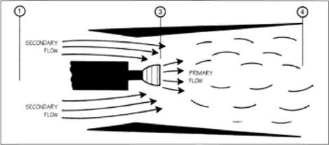
Ejector ramjet. Primary flow from a ducted rocket entrains a substantial secondary flow of external air. (U. S. Air Force) |
vehicle topped a critical speed and the engine continued to burn with no diminution of thrust.
The turboramjet arrangement of the XF-103 also operated in two modes, serving both as a turbojet and as a ramjet. Here, however, the engine employed two sets of hardware, which were physically separate. They shared a common inlet and nozzle, while the ramjet also served as the turbojet’s afterburner. But only one set of equipment operated at any given time. Moreover, they were mounted separately and were not extensively integrated.40
System integration was the key concept within a third class of prime mover: the combined-cycle engine, which sought to integrate two separate thrust-producing cycles within a single set of hardware. In contrast to the turboramjet of the XF-103, engines of this type merged their equipment rather than keeping them separate. Two important concepts that did this were the ejector ramjet, which gave thrust even when standing still, and the Liquid Air Cycle Engine (LACE), which was an airbreathing rocket.
The ejector ramjet amounted to a combined-cycle system derived from a conventional ramjet. It used the ejector principle, whereby the exhaust of a rocket motor, placed within a duct, entrains a flow of air through the ducts inlet. This increases the thrust by converting thermal energy, within the hot exhaust, to mechanical energy. The entrained air slows and cools the exhaust. The effect is much the same as when designers improve the performance of a turbojet engine by installing a fan.
Ejectors date back to the nineteenth century. Horatio Phillips, a pioneer in aeronautical research, used a steam ejector after 1870 to build a wind tunnel. His ejector was a ring of pipe pierced with holes and set within a duct with the holes facing downstream. Pressurized steam, expanding through the holes, entrained an airflow
|
SE;скг;лйч/рйінайт MAS? fi, qh patio |
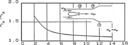
Performance of an ejector. Even with minimal flow of entrained air, the pressure ratio is much lower than that of a turbojet. A pressure ratio of 1.5 implied low efficiency. (Courtesy of William Escher) within the duct that reached speeds of 40 mph, which served his studies.41 Nearly a century later ejectors were used to evacuate chambers that conducted rocket-engine tests in near-vacuum, with the ejectors rapidly pumping out the rocket exhaust. Ejectors also flew, being used with both the F-104 and the SR-71. Significantly, the value of an ejector could increase with Mach. On the SR-71, for instance, it contributed only 14 percent of the total thrust at Mach 2.2, but accounted for 28 percent at Mach 3.2.42
Jack Charshafian of Curtiss-Wright, director of development of ramjets for Navaho, filed a patent disclosure for an ejector rocket as early as 1947. By entraining outside air, it might run fuel-rich and still burn all its fuel. Ejector concepts also proved attractive to other aerospace pioneers, with patents being awarded to Alfred Africano, a founder of the American Rocket Society; to Hans von Ohain, an inventor of the turbojet; and to Helmut Schelp, who stirred early interest in military turbojets within the Luftwaffe.43
A conventional ramjet needed a boost to reach speeds at which its air-ramming effect would come into play, and the hardware requirements approached those of a complete and separate flight vehicle. The turbojet of the XF-103 exemplified what was necessary, as did the large rocket-powered booster of Navaho. But after I960 the ejector ramjet brought the prospect of a ramjet that could produce thrust even when on the runway. By placing small rocket engines in a step surrounding a duct, a designer could leave the duct free of hardware. It might even sustain supersonic combustion, with the engine converting to a scramjet.
The ejector ramjet also promised to increase the propulsive efficiency by improving the match between flight speed and exhaust speed. A large mismatch greatly reduces the effectiveness of a propulsive jet. There would be little effective thrust,
for instance, if one had a jet velocity of 10,000 feet per second while flying in the atmosphere at 400 feet per second. The ejector promised to avoid this by slowing the overall flow.
The ejector ramjet thus offered the enticing concept of a unified engine that could propel a single-stage vehicle from a runway to orbit. It would take off with ejector-boosted thrust from its rocket, accelerate through the atmosphere by using the combination as an ejector-boosted ramjet and scramjet, and then go over completely to rocket propulsion for the final boost to orbit.
Yet even with help from an ejector, a rocket still had a disadvantage. A ramjet or scramjet could use air as its oxidizer, but a rocket had to carry heavy liquid oxygen in an onboard tank. Hence, there also was strong interest in airbreathing rockets. Still, it was not possible to build such a rocket through a simple extension of principles applicable to the turbojet, for there was a serious mismatch between pressures available through turbocompression and those of a rockets thrust chamber.
In the SR-71, for instance, a combination of inlet compression and turbocompression yielded an internal pressure of approximately 20 pounds per square inch (psi) at Mach 3 and 80,000 feet. By contrast, internal pressures of rocket engines started in the high hundreds of psi and rapidly ascended into the thousands for high performance. Unless one could boost the pressure of ram air to that level, no airbreathing rocket would ever fly.44
The concept that overcame this difficulty was LACE. It dated to 1954, and Randolph Rae of the Garrett Corporation was the inventor. LACE used liquid hydrogen both as fuel and as a refrigerant, to liquefy air. The temperature of the liquid hydrogen was only 21 K, far below that at which air liquefies. LACE thus called for incoming ram air to pass through a heat exchanger that used liquid hydrogen as the coolant. The air would liquefy, and then a pump could raise its pressure to whatever value was desired. In this fashion, LACE bypassed the restrictions on turbocompression of gaseous air. In turn, the warmed hydrogen flowed to the combustion chamber to burn in the liquefied air.45
At the outset, LACE brought a problem. The limited thermal capacity of liquid hydrogen brought another mismatch, for the system needed eight times more liquid hydrogen to liquefy a given mass of air than could burn in that mass. The resulting hydrogen-rich exhaust still had a sufficiently high velocity to give LACE a prospective advantage over a hydrogen-fueled rocket using tanked oxygen. Even so, there was interest in “derichening” the fuel-air mix, by making use of some of this extra hydrogen. An ejector promised to address this issue by drawing in more air to burn the hydrogen. Such an engine was called a ramLACE or scramLACE.46
A complementary strategy called for removal of nitrogen from the liquefied air, yielding nearly pure liquid oxygen as the product. Nitrogen does not support combustion, constitutes some three-fourths of air by weight, and lacks the redeeming quality of low molecular weight that could increase the exhaust velocity. Moreover,
a hydrogen-fueled rocket could give much better performance when using oxygen rather than air. With oxygen liquefying at 90 К while nitrogen becomes a liquid at 77 K, at atmospheric pressure the prospect existed of using this temperature difference to leave the nitrogen unliquefied. Nor would it be useless; it could flow within a precooler, an initial heat exchanger that could chill the inflowing air while reserving the much colder liquid hydrogen for the main cooler.
It did not appear feasible in practice to operate a high-capacity LACE air lique – fier with the precision in temperature that could achieve this. However, a promising approach called for use of fractional distillation of liquid air, as a variant of the process used in oil refineries to obtain gasoline from petroleum. The distillation process promised fine control, allowing the nitrogen to boil off while keeping the oxygen liquid. To increase the throughput, the distillation was to take place within a rotary apparatus that could impose high g-loads, greatly enhancing the buoyancy of the gaseous nitrogen. A LACE with such an air separator was called ACES, Air Collection and Enrichment System.47
When liquid hydrogen chilled and liquefied the nitrogen in air, that hydrogen went only partially to waste. In effect, it transferred its coldness to the nitrogen, which used it to advantage in the precooler. Still, there was a clear prospect of greater efficiency in the heat-transfer process if one could remove the nitrogen directly from the ram air. A variant of ACES promised to do precisely this, using chemical separation of oxygen. The process relied on the existence of metal oxides that could take up additional oxygen when heated by the hot ram air and then release this oxygen when placed under reduced pressure. Only the oxygen then was liquefied. This brought the increased efficiency, for the amount of liquid hydrogen used as a coolant was reduced. This enhanced efficiency also translated into conceptual designs for chemical-separation ACES units that could be lighter in weight and smaller in size than rotary-distillation counterparts.48
Turboramjets, ramjets, scramjets, LACE, ramLACE and scramLACE, ACES: with all these in prospect, designers of paper engines beheld a plenitude of possibilities. They also carried a strong mutual synergism. A scramjet might use a type of turboramjet for takeoff, again with the scramjet duct also functioning as an afterburner. Alternately, it might install an internal rocket and become a scramLACE. It could use ACES for better performance, while adopting the chemical-separation process to derichen the use of hydrogen.
It did not take long before engineers rose to their new opportunities by conceiving of new types of vehicles that were to use these engines, perhaps to fly to orbit as a single stage. Everyone in aerospace was well aware that it had taken only 30 years to progress from Lindbergh in Paris to satellites in space. The studies that explored the new possibilities amounted to an assertion that this pace of technical advance was likely to continue.


