Category Soviet x-plenes

Mikhel’sonMP

Purpose: To build a faster torpedo-carrying aircraft.

Design Bureau: Factory No 3 Krasnyi Lyotchik ‘Red Flyer’, Leningrad, see below.

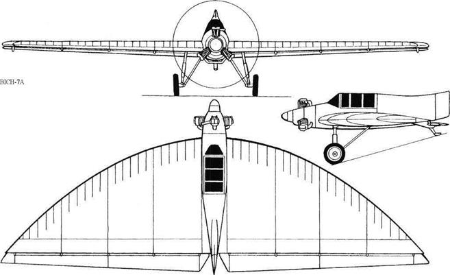
The designation MP derived from Morskoi Podvesnoi, naval suspended. The reasoning began with the belief that to attack a heavily defended ship called for a small and agile air­craft with high performance, but that such an aircraft could not have a long range. Accord­ingly engineer N Val’ko suggested carrying the attack aircraft under a large long-range aeroplane in the manner pioneered by Vakhmistrov. In 1936 this concept was ac­cepted by the VMF (war air fleet) and as­signed to N G Mikhel’son in partnership with AI Morshchikhin, with assistance from Vakhmistrov. The design was completed by VVNikitin (see page 145). According to Shavrov ‘During prototype construction nu­merous problems arose, and since half could not be solved it was decided to discontinue development’. In fact, by 1938 the MP was ready for flight, but the political atmosphere (the Terror) was so frightening that nobody dared to sanction the start of flight testing in case anything went wrong. The MP was ac­cordingly given to the Pioneers’ Palace.

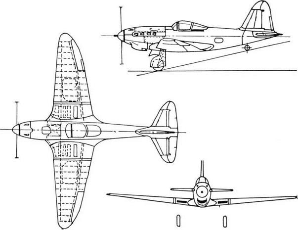
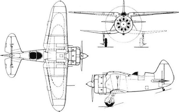
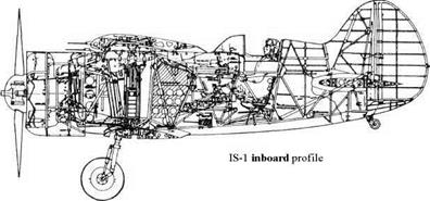
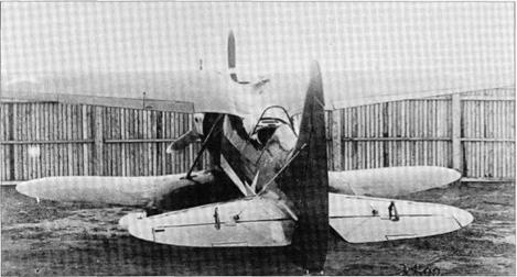
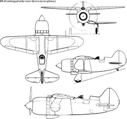
The MP was superficially arranged like a fighter, with an 860hp Hispano-Suiza 12Ybrs engine driving a three-blade propeller and cooled by a radiator in the top of the fuselage behind the cockpit. The airframe was made almost entirely from duralumin, though the basis of the fuselage was a truss of welded Cr-Mo steel tube. The cockpit was enclosed and featured the then-fashionable forward – sloping windscreen. Flight-control surfaces were covered in fabric. The 45-36-AN, a full – size 553mm torpedo, was carried in a large recess under the fuselage. For ground ma­noeuvring the aircraft had wheeled main landing gear and a tailskid. The main gears re­tracted upwards, the shock struts travelling outwards along tracks in the wing. The loaded MP was to be hoisted under a TB-3 carrier aircraft and carried close to the target, such as an enemy fleet. The engine would then be started and the aircraft released, with the TB-3 in a dive to increase speed at release. The MP would then aim its torpedo and fly back to its coastal base. Before landing, the pilot would engage a mechanism which would raise the engine 20° upwards. The MP could then alight on the water and taxi to its mooring. The water landing was facilitated by the high position of the horizontal tail and the
location of the engine radiator on top of the rear fuselage. The unladen aircraft was de­signed to float with the wings just resting on the water (see front view drawing), the wings serving as stabilizing sponsons.

There is no reason to doubt that this scheme might have proved practicable. One of the drawings shows in side elevation a pro­posed faster next-generation aircraft devel­oped from the MP.

Dimensions

Span

8.5m

27 ft 10% in

Length about

8.0m

26 ft 3 in

Wing area

20.0m2

215ft2

Weights Empty about

2,200 kg

4,850 Ib

Loaded

3,200 kg

7,055 Ib

Performance not recorded.

MP, with additional side view of projected high­speed development.

Mikhel’son MP

Mikhel'sonMP


Mikhel'sonMP

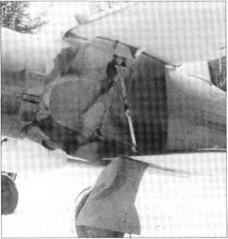
Above and right: Details of engine and radiator (both marked ‘secret’).


MiG 105-11

Purpose: To investigate the low-speed handling within the atmosphere of an orbital shape.

Design Bureau: OKB-155 ofAI Mikoyan.

By 1965 the Mikoyan OKB was deeply into the technology of reusable aero-space vehicles. Under ‘oldest inhabitant’ G Ye Lozino-Lozin – skiy a shape was worked out called BOR (from Russian for pilotless orbital rocket air­craft), and in turn this was the basis for the manned Epos (an epic tale). The BOR test ve­hicles had been fired by rocket and recovered by parachute, but a manned vehicle had to land in the conventional way. It was consid­ered prudent to build a manned test vehicle to explore low-speed handling and landing. Called 105-11, -12 and -13, only the first is be­lieved to have flown. The OKB pilot was Aviard Fastovets, and he began high-speed taxi tests at Zhukovskii in September 1976. On llth October 1976 he took off and climbed straight ahead to 560m (1,837ft). He landed as planned at an airfield about 19km (12 miles) ahead. On 27th November 1977 he entered 105-11 slung under the Mikoyan OKB’s Tu-95K
(previously used for cruise-missile tests) and landed on an unpaved strip after release at 5,000m (16,400ft). The 105-11 made seven further flights, the last in September 1978. It was then retired to the Monino museum.

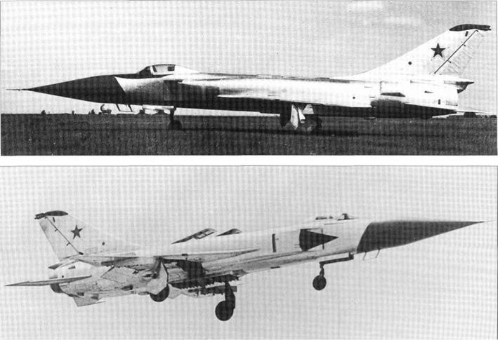
The 105-11 was almost the size of a MiG-21, and was likewise a single-jet tailless delta. The fuselage had a broad ‘waverider’ shape, with a flat underside, and the cockpit at the front was entered via a roof hatch. From the sides projected small swept wings with elevens, and there was a large fin and rudder. The engine was an RD-36-35K turbojet de­rived from the previously used lift engines, rated at 2,000kg (4,409 Ib). It was fed by a dor­sal inlet with an upward-hinged door to fair the engine in when in high-speed gliding flight. Features of the eventual hypersonic Epos included a flat unfaired tail end to the broad fuselage, the upper surface comprising large upward-hinged airbrakes, and a struc­ture designed to accommodate severe ther­mal gradients, though the 105-11 was never designed to fly faster than Mach 0.8. Early test­ing was done with rubber-tyred wheels on the front two retractable legs and steel skis on
the rear pair (the OKB record that the runway was lubricated by crushed melons). For the air-drop tests all four legs had steel skids.

The brief flights ofthe 105-11 confirmed the design of a manned aero-space vehicle, lead­ing to the Buran (see later).

Dimensions

Span

Length (excluding multi- PVD instrument boom) Area ofwing and lifting body

6.7m

vane

10.6m 24.0 nf

21 ft 11% in

34ft93/Sin

258ft2

Weights

Empty

3,500kg

7,716 Ib

Fuel

500kg

1,102 Ib

Loaded

4,220kg

9,300 Ib

Performance

Maximum speed (design) Mach 0.8

(actually reached) about 800km/h 500 mph

Landing speed 250-270 km/h 155-168 mph

105-11, with skids

MiG 105-11


Above left and right: Two views of 105-11.


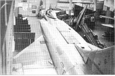
Left 105-11, with skids, preserved at Monino.


MiG 105-11MiG 105-11

Polikarpov Malyutka

Purpose: Short-range interceptor to defend high-value targets.

Design Bureau: OKB ofNikolai N Polikarpov, evacuated to Novosibirsk.

This was the last aircraft of Polikarpov design, and he oversaw its progress himself. It was an OKB project, begun in June 1943. Construc­tion of a single prototype began in early 1944. Progress was rapid until 30th July 1944, when Polikarpov suffered a massive heart attack and died at his desk. Even though the proto­type was almost complete, work stopped and was never resumed.

The key to the Malyutka (‘Little one’) was the existence of the NIl-1 rocket engine. De­veloped by the team led by V P Glushko, this controllable engine had a single thrust cham­ber fed with RFNA (concentrated nitric acid) and kerosene. Maximum thrust at sea level was 1,200kg, but in this aircraft the brochure figure was 1,000kg (2,205 Ib). Bearing no direct
relevance to any previous Polikarpov fighter, the airframe had a curvaceous Shpon (plas­tic-bonded birch laminates) fuselage sitting on a wing of D-l stressed-skin construction. The tail was also D-l alloy. The pressurized cockpit was in the nose, behind which was the radio, oxygen bottles asnd gun maga­zines, followed by a relatively enormous tank of acid and a smaller one of kerosene. The tri­cycle landing gears and split flaps were oper­ated pneumatically, and the armament comprised two powerful VYa-23 cannon.

Had it run a year or two earlier this might have been a useful aircraft, though it offered little that was not already being done by the BI and Type 302. At the same time, the death of the General Constructor should not have brought everything to a halt.

Dimensions (performance

Span

Length

Wing area

estimated)

7.5m

7.3m

8.0m2

24 ft n in

23 ft 11 Min 86ft2

Weights

Empty

1,016kg

2,240 Ib

Propellants

1,500kg

3,307Ib

Loaded

2,795kg

6,162 Ib

Performance

Max speed at sea level

890 km/h

553 mph

Time to climb to 5 km

1 min

16,404ft

Service ceiling

16km

52,500 ft

Landing speed (empty tanks) 135 km/h

84 mph

Malyutka


Polikarpov MalyutkaPolikarpov Malyutka

Sukhoi Su-37

Подпись: Below: T1Q1A-11.

Purpose: To create the optimised multirole fighter derived from the Su-27.

Design Bureau: AOOT ‘OKB Sukhoi’, Moscow.

The superb basic design of the T-10 led not only to the production Su-27 but also to sev­eral derivative aircraft. Some, such as the Su-34, are almost completely redesigned for new missions. One of the main objectives has been to create even better multirole fighters, and via the Su-27UB-PS and LMK 24-05 Sukhoi and the Engine KB ‘Lyul’ka-Saturn’ have, in partnership with national laborato­ries and the avionics industry, created the Su-37. The prototype was the T10M-11, tail number 711, first flown on 2nd April 1996. The engine nozzles were fixed on the first flight, but by September 1996, when it arrived at the Farnborough airshow, this aircraft had made 50 flights with nozzles able to vector. At the British airshow it astounded observers by going beyond the dramatic Kobra manoeuvre and making a complete tight 360° somersault essentially within the aircraft’s own length and without change in altitude. Called Kulbit (somersault), this manoeuvre has yet to be emulated by any other aircraft. In 1999 low-rate production was being planned at Komsomolsk.

Essentially the Su-37 is an Su-35 with vec­toring engines. Compared with the Su-27 the Su-35 has many airframe modifications in­cluding canards, taller square-top fins (which are integral tanks) and larger rudders, dou­ble-slotted flaps, a bulged nose housing the electronically scanned antenna of the N011M radar, an extended rear fuselage housing the aft-facing defence radar, twin nosewheels and, not least, quad FBW flight controls able to handle a longitudinally unstable aircraft. In addition to these upgrades the Su-37 has AL-31FP engines, each with dry and aug­mented thrust of 8,500 and 14,500kg (18,740 and 31,9671b) respectively. These engines have efficient circular nozzles driven by four pairs of actuators to vector ±15° in pitch. Left/right vectoring is precluded by the prox­imity of the enlarged rear fuselage, but engine General Designer Viktor Chepkin says ‘Differ­ential vectoring in the vertical plane is syn­onymous with 3-D multi-axis nozzles’. In production engines the actuators are driven by fuel pressure.

It is difficult to imagine how any fighter with fixed-axis nozzles could hope to survive in any kind of one-on-one engagement with this aircraft.

Dimensions

Span (over ECM containers)

Length

Wing area

15.16m

22.20m

62.0m2

49 ft 8k! in 72 ft 10 in 667ft2

Weights

Weight empty

17tonnes

37,479 Ib

Maximum loaded

34 tonnes

74,956 Ib

Performance

Maximum speed

at sea level

l,400km/h

870mph(Machl. l4)

at high altitude

2,500 km/h

1,553 mph (Mach 2.35)

Rate of climb

230 m/s

45,276 ft/min

Service ceiling

18,800m

61,680ft

Range (internal fuel)

3,300 km

2,050 miles

Purpose: To provide data to support the design of a superior air-combat fighter. Design Bureau: AOOT ‘OKB Sukhoi’, Moscow.

Almost unknown until its first flight, this air­craft is one of the most remarkable in the sky. Any impartial observer cannot fail to see that, unless Sukhoi’s brilliance has suddenly be­come dimmed, it is a creation of enormous importance. Like the rival from MiG, it pro­vides the basis for a true ‘fifth-generation’ fighter which with rapid funding could swiftly become one of the greatest multirole fighters in the world. Unfortunately, in the Russia of today it will do well to survive at all, especial­ly as the WS has for political and personality reasons shown hostile indifference. In fact on 1st February 1996, when the first image of a totally new Sukhoi fighter leaked out in the form of a fuzzy picture of a tabletop model, the WS Military Council instantly proclaimed that this aircraft ‘is not prospective from the point of view of re-equipment within 2010­25’. In fact the first hint of this project came during a 1991 visit by French journalists to CAHI (TsAGI), when they were shown a
model of an aircraft with FSW (forward – swept wings) and canard foreplanes called the Sukhoi S-32. At the risk of causing confu­sion, Sukhoi uses S for projects and Su for products, the same number often appearing in both categories but for totally different air­craft (for example, the Su-32 is piston-en­gined). In December 1993, during the Institute’s 75th-birthday celebrations, its work on the FSW was said to be ‘for a new fighter of Sukhoi design’. The model shown in Feb­ruary 1996 again bore the number ’32’ but clearly had tailplanes as well as canards. It had been known for many years that the FSW has important aeroelastic advantages over the traditional backswept wing (see OKB-1 bombers and Tsybin LL). At least up to Mach 1.3 (1,400 tol,500km/h, 870 to 930mph) the FSW offers lower drag and superior manoeu­vrability, and the lower drag also translates as longer range. A further advantage is that take­offs and landings are shorter. The fundamen­tal aeroelastic problem with the FSW can be demonstrated by holding a cardboard wing out of the window of a speeding vehicle. A cardboard FSW tends to bend upwards vio­lently, out ofcontrol. An FSW for a fastjet was

Подпись: S-37 Berkut

thus very difficult to make until the technolo­gy of composite structures enabled the wing to be designed with skins formed from multi­ple layers of adhesive-bonded fibres of car­bon or glass. With such skins the directions of the fibres can be arranged to give maximum strength, rather like the directions of the grain in plywood. The first successful jet FSW was the Grumman X-29, first flown in December 1984. This exerted a strong influence on the Sukhoi S-32 design team, which under Mikhail Simonov was led by First Deputy Gen­eral Designer Mikhail A Pogosyan, and in­cluded Sergei Korotkov who is today’s S-37 chief designer. From 1983 the FSW was ex­haustively investigated, not only by aircraft OKBs but especially by CAHI (TsAGI) and the Novosibirsk-based SibNIA, which tunnel-test­ed several FSW models based loosely on the Su-27. By 1990 Simonov was determined to create an FSW prototype, and three years later the decision had been taken not to wait for non-existent State funds but instead to put every available Sukhoi ruble into constructing such an aircraft. Despite a continuing ab­sence ofofficial funding, this has proved to be possible because of income from export

Подпись:
sales of fighters ofthe Su-27 family. Construc­tion began in early 1996, but in that year Western aviation magazines began chanting that the S-32 was soon to fly. Uncertain about the outcome, Simonov changed the designa­tion to S-37, so that he could proclaim The S-32 does not exist’. It had been hoped to fly the radical new research aircraft at the MAKS – 97 airshow, but it was not ready in time. It was a near miss, because the almost completed S-37 had begun ground testing in July, and by August it was making taxi tests at LII Zhukovskii, the venue for the airshow. After MAKS 97 was over it emerged again, and on 25th September 1997 it began its flight test programme. The assigned pilot is Igor Vik­torovich Votintsev. A cameraman at the LII took film which was broadcast on Russian TV, when the aircraft was publicised as the Berkut (golden eagle). On its first flight, when for a while the landing gear was retracted, the S-37 was accompanied by a chase Su-30 car­rying a photographer. It is a long way from being an operational fighter, but that is no rea­

son for dismissing it as the WS, Ministry of Defence and the rival MiG company have done. Fortunately there are a few objective people in positions of authority, one being Marshal Yevgenii Shaposhnikov, former WS C-in-C. Despite rival factions both within the WS and industry (and even within OKB Sukhoi) this very important aircraft has made it to to the flight-test stage. Whether it can be made to lead to a fully operational fighter is problematical.

The primary design objective ofthis aircraft is to investigate the aerodynamics and con­trol systems needed to manoeuvre at angles of attack up to at least 100°. From the outset it was designed to be powered by two AL-41F augmented turbofans from Viktor Chepkin’s Lyul’ka Saturn design bureau. In 1993 he con­fidentially briefed co-author Gunston on this outstanding engine. At that time it had already begun flight testing under a Tu-16 and on one side of a M1G-25PD (aircraft 84-20). Despite this considerable maturity it was not cleared as the sole source of propulsion in time for the S-37, though the aircraft could be re-engined later. Accordingly the Sukhoi prototype is at

Sukhoi Su-37

present powered by two AL-31F engines, with dry and afterburning thrusts of 8,100 and 12,500kg (17,557 and 27,560 Ib), respectively. Special engines were tailored to suit the S-37 installation, but at the start of the flight pro­gramme they still lacked vectoring nozzles. The engines are mounted only a short dis­tance apart, fed by ducts from lateral inlets of the quarter-circle type. At present the inlets are of fixed geometry, with inner splitter plates standing away from the wall of the fuselage and bounded above by the under­side ofthe very large LERX (leading-edge root extension), which in fact is quite distinct from the root of the wing. The wing itself compris­es an inboard centroplan with leading-edge sweep of 70°, leading via a curved corner to the main panel with forward sweep of 24° on the leading edge and nearly 40° on the trailing edge. The forward-swept portion has a two – section droop flap over almost the whole leading edge, and plain trailing-edge flaps and outboard ailerons. Structurally it is de­scribed as ’90 per cent composites’. The main wing panels are designed so that in a derived aircraft they could fold to enable the aircraft

Sukhoi Su-37

to fit into the standard Russian hardened air­craft shelter. Aerodynamically the S-37 is an­other ‘triplane’, having canard foreplanes as well as powered tailplanes. The former are greater in chord than those of later Su-27 de­rivatives, the trailing edge being tapered in­stead of swept back. Likewise the tailplanes have enormous chord, but as the leading – edge angle is over 75° their span is very short. As in other Sukhoi fighters, the tailplanes are pivoted to beams extending back from the wing on the outer side of the engines. Unlike previous Sukhois the tailplanes are not mounted on spigots on the sides of the beams but on transverse hinges across their aft end. These beams also carry the fins and rudders, which are similar to those of other Sukhois apart from being further apart (a long way outboard of the engines) and canted out­ward. After flight testing had started the rud­ders were given extra strips (in Russia called knives) along the trailing edge. When the S-37 is parked, with hydraulic pressure decayed, the foreplanes, tailplanes and ailerons come to rest 30° nose-up. The landing gear is almost identical to that ofthe Su-27K, with twin steer­able nosewheels. In the photographs re­leased so far no airbrakes or centreline braking-parachute container can be seen. In­

ternal fuel capacity is a mere 4,000kg (8,8181b), though much more could be ac­commodated. The cockpit has an Su-27 type upward-hinged canopy, and a sidestick on the right. The airframe makes structural pro­vision for 8 tonnes (17,637 Ib) of external and internal weapons, including a gun in the left centroplan. It is also covered in numerous flush avionics antennas, though the only ones that are functional are those necessary for aerodynamic and control research. A bump to starboard ahead of the wraparound wind­screen could later contain an opto-electronic (TV, IR, laser) sight, while the two tail beams are continued different distances to the rear to terminate in prominent white domes, doubtless for avionics though they could con­ceivably house braking parachutes. These domes stand out against the startling dark blue with which this aircraft has been paint­ed. Sukhoi has stressed that this aircraft in­corporates radar-absorbent and beneficially reflective ‘stealth’ features, though again the objective is research. Also standing out visu­ally are the white-bordered red stars, though of course the aircraft is company-owned and bears ‘OKB Sukhoi’ in large yellow characters on the fuselage, along with callsign 01, which confusingly is the same as the MiG 1.44.

The Russians have traditionally had a strong aversion to what appear to be uncon­ventional solutions, and this has in the past led to the rejection of many potentially out­standing aircraft. The S-37 has to overcome this attitude, as well as the bitter political struggle within the OKB, with RSK MiG, with factions in the Ministry of Defence and air force and, not least, two banks which are bat­tling to control the OKB.

Dimensions

Span 16.7m 54 ft m in

Length (ex PVO boom) 22.6m 74 ft 1% in

Wing area about 67m2 721 ft2

Weights

Take-off mass given as 24 tonnes 52,910 Ib

(the design maximum is higher)

Performance

Design maximum speed 1,700 km/h, 1,057 mph (Mach 1.6)

(which would explain the fixed-geometry inlets. At Mach numbers much higher than this the FSW is less attractive)

At press time no other data had emerged.

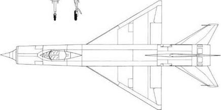
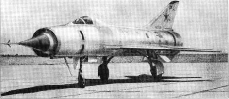
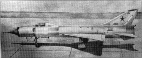
Purpose: To study wings for transonic flight. Design Bureau: OKB-256, ChiefDesigner Pavel Vladimirovich T sybin, professor at Zhukovskii academy.

In September 1945 the LIl-MAP (Flight Re­search Institute) asked Tsybin to investigate wings suitable for flight at high Mach num­bers (if possible, up to 1). In 1946 numerous models were tested at CAHI (TsAGI), as a re­sult of which OKB-256 constructed the Ts-1, also called LL-1 (flying laboratory 1). Almost in parallel, a design team at the OKB led by A V Beresnev developed a new fuselage and tail and two new wings, one swept back and the other swept forward. The LL-1 made 30 flights beginning in mid-1947 with NIl-WS pilot M Ivanov, and continuing with Amet- Khan Sultan, S N Anokhin and N S Rybko. On each flight the aircraft was towed by a Tu-2. Casting off at 5-7km (16,400-23,000ft), the air­craft was dived at 45°-60° until at full speed it was levelled out and the rocket fired. In win­ter 1947-48 the second Ts-1 was fitted with the swept-forward wing to become the LL-3. This made over 100 flights, during which a speed of l,200km/h (746mph) and Mach 0.97 were reached, without aeroelastic problems and yielding much information. The swept – back wing was retrofitted to the first aircraft to create the LL-2, but this was never flown.

Sukhoi Su-37Подпись: LL-3Sukhoi Su-37Подпись:Sukhoi Su-37The original Ts-1 (LL-1) was essentially all­wood. The original wing had two Delta (resin – bonded ply) spars, a symmetric section of 5 per cent thickness, 0° dihedral and +2° inci­dence. It had conventional ailerons and plain flaps (presumably worked by bottled gas pressure). Take-offs were made from a two – wheel jettisonable dolly, plus a small tail – wheel. In the rear fuselage was a PRD-1500 solid-propellant rocket developed by 11 Kar – tukov, giving 1,500kg (3,307 Ib) (more at high altitude) for eight to ten seconds. Flight con­trols were manual, with mass balances. On early flights no less than one tonne (2,2051b) of water was carried as ballast, simulating in­strumentation to be installed later. This was jettisoned before landing, when the aircraft (now a glider) was much more manoeu­vrable. Landings were made on a skid. Vari­ous kinds of instrumentation were carried, and at times at least one wing was tufted and photographed. The LL-3 was fitted with a metal wing with a forward sweep of 30° (ac­cording to drawings this was measured on the leading edge), with no less than 12° dihe­dral. The new tailplane had a leading-edge sweepback of 40°. To adjust the changed cen­tres of lift and of gravity new water tanks were fitted in the nose and tail. Both LL-1 and LL-3 were considered excellent value for money.

Sukhoi Su-37

Left: LL-1.

Below left: LL-2.

Below: LL-2, left wing tufted.


LL-3, showing take-off trolley


Dimensions (LL-3)

Span

Length

Wing area

7.22m

8.98m

10.0m2

23 ft 814 in 29 ft 5Л in 108ft2

Weights

Loaded

2,039kg

4,495 Ib

Landing

1,100kg

2,425 Ib

Performance

Maxspeedreached

l,200km/h

746 mph

Landing speed

120km/h

74.6 mph


Sukhoi Su-37Sukhoi Su-37Sukhoi Su-37Sukhoi Su-37

Purpose: To create a winged strategic delivery vehicle.

Design Bureau: OKB-256, Podberez’ye, Director P V Tsybin.

In the early 1950s it was evident that the forth­coming thermonuclear weapons would need strategic delivery systems of a new kind. Until the ICBM (intercontinental ballistic missile) was perfected the only answer appeared to be a supersonic bomber. After much plan­ning , Tsybin went to the Kremlin on 4 th March 1954 and outlined his proposal for a Reak – tivnyi Samolyot (jet aeroplane). The detailed and costed Preliminary Project was issued on 31st January 1956, with a supplementary sub­mission of a reconnaissance version called 2RS. Korolyov’s rapid progress with the R-7 ICBM (launched 15th May 1957 and flown to its design range on 21st August 1957) caused the RS to be abandoned. All effort was trans­ferred to the 2RS reconnaissance aircraft (de­scribed next).

The RS had an aerodynamically brilliant configuration, precisely repeated in the British Avro 730 which was timed over a year later. The wing was placed well back on the long circular-section fuselage and had a sym­metric section with a thickness/chord ratio of 2.5 to 3.5 per cent. It had extremely low as­pect ratio (0.94) and was sharply tapered on both edges. Large-chord flaps were provided inboard of conventional ailerons, other flight
controls comprising canard foreplanes and a rudder, all surfaces being fully powered. The cockpit housed a pilot in a pressure suit, seat­ed in an ejection-seat under a canopy linked to the tail by a spine housing pipes and con­trols. The RS was to be carried to a height of 9km (29,528ft) under a Tu-95N. After release it was to accelerate to supersonic speed (de­sign figure 3,000km/h) on the thrust oftwo jet­tisoned rocket motors. The pilot was then to start the two propulsion engines, mounted on the wingtips. These were RD-013 ramjets, de­signed by Bondaryuk’s team at OKB-670. Each had a fixed-geometry multi-shock inlet and convergent/divergent nozzle matched to the cruise Mach number of 2.8. Internal di­ameter and length were respectively 650mm (2ft IHin) and 5.5m (18ft 1/2in). The 1955 pro­ject had 16.5 tonnes offuel, or nearly 3.5 times the 4.8-t empty weight, but by 1956 the latter had grown and fuel weight had in conse­quence been reduced. The military load was to be a 244N thermonuclear bomb weighing 1,100kg (2,4251b). The only surviving drawing shows this carried by a tailless-delta missile towed to the target area attached behind the RS fuselage (see below). Data for this vehicle are not known.

Outstandingly advanced for its day, had this vehicle been carried through resolutely it would have presented ‘The West’ with a seri­ous defence problem.

Dimensions

Span (over engine centrelines) 9.0 m

29 ft 6% in

Basic wing

7.77 m

25ft53/4in

Foreplane

3.2 m

10 ft 6 in

Length

27.5 m

90 ft 2% in

Wing area

64 m2

689ft2

Weights

Empty

5,200 kg

ll,4641b

Fuel

10,470kg

23,082 Ib

Maximum take-off weight

2 1 , 160 kg

46,649 Ib

Performance

Range at 3,000 km/h (1,864 mph, Mach 2.82)

at 28 km (91 ,864 ft) altitude 13,500 km

8,389 miles

Landing speed/

245 km/h

152 mph

run

1,100m

3,610ft

RS


Sukhoi Su-37Sukhoi Su-37

Antonov M

Purpose: To create a superior jet fighter.

Design Bureau: No 153, Oleg K Antonov, Novosibirsk.

In 1945 Antonov was impressed by the German He 162, and consid­ered it a good way to produce a simple fighter for rough-field use pow­ered by a single turbojet. In spring 1947 his staff had completed the design of the SKh (later designated An-2), and he quickly schemed a fighter to be powered by a single RD-10 (Soviet-made Junkers Jumo 004B) above the fuselage. He tested a tunnel model, but on 6th April 1947 received an instruction from NKAP (the state commissariat for aviation industry) to design a fighter with two RD-lOs. By this time he had recognized that jet engines not only made possible unconven­tional new configurations for fighters but might even demand them. He quickly roughed out the Masha, abbreviated as the ‘M’. A A Batu – mov and V A Dominikovskiy were appointed chief designers, with 11 Yegorychev in charge of construction. Design was virtually com­plete when in late 1947 the NKAP instructed OKB-153 to redesign the aircraft to use the RD-45, the Soviet-built copy ofthe Rolls-Royce Nene. Apart from the forward fuselage, the redesign was total. Following tunnel testing of models, and free-flight testing of the E-153 (which was used as both a detailed full-scale wooden mock-up and a towed glider), construction of the M prototype went ahead rapidly. In July 1948, when the prototype was almost ready, and Mark L Gallai was about to begin flight testing, the project was cancelled. The La, MiG and Yak jet fighters were thought sufficient. (In 1953 Antonov again schemed a j et fighter, this time a tailed delta powered by an AL-7F, but it remained on paper.)

The original 1947 form of the Masha featured side inlets to the RD – 10 engines buried in the thick central part of the wing. Outboard were

Antonov M

Model of the 1947 jet fighter project.

broad wings tapered on the leading edge with squared-off tips carry­ing swept fins and rudders. Beyond these were small forward-swept ailerons. The main wing had leading-edge flaps and aft spoilers. Hav­ing studied side doors to the cockpit, Antonov settled for a sliding canopy. Armament comprised two VYa-23 and two B-20. This arma­ment remained unchanged in the M actually built, which had a single RD-45, rated at 2,270kg (5,000 Ib) fed by cheek inlets. The wing was re­designed as a round-tipped delta, with the swept vertical tails posi­tioned between two pairs of tabbed elevons.

Antonov considered that the final M ought to have been allowed to fly. He considered it would have dramatically outmanoeuvred any contemporary competition, and could later have had radar and a more powerful engine.

Antonov M

Dimensions (data 194 7)

Span

Length

10.8m

10.6m

35 ft 5 in 34 ft 914 in

Dimensions (data 1948) Span

9.3m

30 ft &/, in

Length

10.64m

34 ftQ/, in

No other data.


Antonov M

! I


! [

*J


Original scheme for M, 1947


Definitive M, 1948


Antonov MAntonov MAntonov M

Antonov MПодпись: Three photographs of the An-181

Purpose: To explore the Custer channel­wing concept.

Design Bureau: Oleg K Antonov, Kiev, Ukraine.

Little is known about this research aircraft, other than what could be gleaned by walking round it on 18th August 1990 and reading the accompanying placard. Its one public outing was on Soviet Day of Aviation, and the venue the airfield at the village of Gastomel, near Kiev. The configuration was instantly recog­nisable as being that of the ‘channel-wing’ air­craft proposed by American W R Custer in the mid-1950s. The key factor of this concept was powered lift gained by confining the pro­peller slipstream in a 180° half-barrel of aero­foil profile. Custer claimed the ability to take off and climb almost vertically, or to hover, whilst retaining full forward speed capability. Resurrecting the Custer concept was aston­ishing, as the claims for the channel-wing air­craft were soon shown to be nonsense, and instead of 1958 being the start of mass-pro­duction of the CCW-5 series version the whole thing faded from view. It was thus to­tally unexpected when the ‘181’ appeared at an Open Day hosted by the Antonov OKB. It was not just parked on the grass but tied down on a trailer. Visitors were able to climb on to this and study the aircraft intimately, but there was nobody to answer questions.

The ‘181’ was dominated by its two Custer – inspired channel wings, with aerofoil lifting surfaces curved round under the propellers so that they were washed by the slipstream. Whereas the Custer CCW-5 had pusher pro­pellers above the trailing edge, the Antonov aircraft had tractor propellers above the lead­ing edge. They were driven via shafts and gears by a 210hp Czech M-337A six-cylinder aircooled piston engine. Apart from this the aircraft appeared conventional, though the tail was of ‘butterfly’ configuration to keep it out of the slipstream, and of exceptional size in order to remain effective at very low air­speeds. Beyond the channel wings were small outer wings with ailerons. The nose was fighter-like, with a large canopy over the side-by-side cockpit, and the tricycle landing gear was fixed. The nose carried a long in­strumentation boom, and there was a dorsal antenna, presumably for telemetry. The whole aircraft was beautifully finished, and painted in house colours with the Antonov logo. It bore Soviet flags on the fins, and civil registration SSSR-190101.

Construction of this research aircraft must have been preceded by testing of models. These must have given encouraging results, which were not reproduced in the ‘181’. Co­author Gunston asked Antonov leaders about the ‘181’ and was told that it had been a seri­ous project, but perhaps ought not to have been put on view.

Dimensions

Span

Length

Wing area (total projected)

7.3m

7.31m

7.0m2

23 ft m in

23 ft 11% in 75 ft2

Weights

Weight loaded (normal)

820kg

l,8081b

(maximum)

900kg

l,9841b

Performance

Maximum speed (placard)

820 km/h

510 mph

Range (placard)

750km

466 miles

BOK-1, SS

Purpose: To investigate high-altitude flight, and if possible set records.

Design Bureau: The Byuro Osobykh Konstruktsii, the Bureau of Special Design, Smolensk. BOK was formed in 1930 in Moscow as a subsidiary of CAHI (TsAGI) to build experimental aircraft ordered by the Revolutionary Military Council. Despite starting on existing projects it made slow progress, and in September 1931 was transferred to the CCB (TsKB) as Brigade No 6. It had undergone other transformations, and been relocated at Smolensk, by the time work began on BOK – 1. Director and Chief Designer was Vladimir Antonovich Chizhevskii.

One of the bureau’s first assignments was to create an aircraft to explore flight at extreme altitudes, seen as ‘Nol priority’. Close links between the USSR and Junkers resulted in BOK sending a team to Dessau in 1932 to
study the Ju 49, and in particular its pressur­ized cabin. This strongly influenced their thinking, and led to many studies for a Soviet counterpart, but the only hardware built was the balloon SSSR-1, with a pressur­ized gondola, which in 1933 exceeded 18km (59,055ft). In 1934 a major conference of the Academy of Sciences issued a programme for future research, one requirement being a high-altitude aircraft. The contract for the SS (Stratosfernyi Samolyot, stratospheric aero­plane) was signed with BOK.

By this time Tupolev had designed the long – range RD (ANT-25), and to save time BOK used this as the basis for the BOK-1. The main task was to design the pressure cabin, but there were many other major modifications. The BOK-1 was built at GAZ (State Aircraft Factory) No 35 at Smolensk, where it was first flown by I F Petrov in (it is believed, in Sep­tember) 1936. It was repeatedly modified in order to climb higher. It was successfully put
throughGOSNIl-GVF State testing by PM Ste – fanovskii. Shavrov speaks of’ a lighter variant’ achieving greater heights, but there is no evi­dence of a second BOK-1 having been built.

The airframe was originally that of one of the military RD aircraft, but modified by GAZ No 35. The span was reduced by fitting new constant-taper outer panels, restressed for significantly reduced gross weight achieved by greatly reducing the fuel capaci­ty. The massive retractable twin-wheel main landing gears were replaced by lighter fixed units with spatted single wheels. The engine was an AM-34RN liquid-cooled V-12, rated at 725hp, driving a three-blade fixed-pitch propeller.

The main new feature was the pressure cabin, seating the pilot and a backseater who acted as observer, navigator and radio opera­tor (though no radio was ever installed). This cabin was a sealed drum of oval cross-sec­tion, with closely spaced frames to bear the

BOK-1


BOK-1, SS

bursting stress, constructed of Dl light alloy with 1.8 or 2.0mm skin riveted over a sealing compound. Design dP (pressure differential) was 0.22kg/cm2 (3.2 lb/in2). The front and rear were sealed by convex bulkheads. The entry hatch was at the rear and an escape hatch was provided in the roof. One report says there was no room for parachutes, which were stowed in the rear fuselage. There were five small glazed portholes for the pilot and one on each side ahead of the backseater. There were also four small portholes to admit light to the unpressurized rear fuselage. A re­generative system circulated the cabin air and removed carbon dioxide (one report says ‘and nitrogen’). A controlled leak through a dump valve was made good by oxygen from bottles to keep oxygen content approximate­ly constant. The engine cooling circuit heated a radiator covering the cabin floor to keep in­ternal temperature at 15-18°C.

Flight testing revealed satisfactory flying characteristics and a lack of vibration. On the other hand, on any prolonged flight the cabin became uncomfortably hot. Despite this, and electric heating of the portholes, the glazed surfaces quickly misted over. In any case, ex­ternal vision was judged dangerously inade­quate.

Shavrov states that the cabin was qualified for flight to ‘8,000m and more’; this is am­biguous, and the original design objective was that the interior should be equivalent to an altitude of 8,000m (26,250ft) at the design ceiling of the aircraft. The engine cooling cir­cuit was modified, and the portholes were re­placed by double-layer sandwiches with not only electric heating but also a dessicant (moisture absorber) between the panes. This overcame the condensation, but nothing could be done to improve field of view.

In spring 1937 the BOK-1 was fitted with an 830hp M-34RNV engine, driving a four-blade fixed-pitch propeller. This engine was then fit­ted with two TK-1 turbosuperchargers, de­signed by VI Dmitriyevskiy so that the combined turbo exhausts also added a thrust of 70kg (1541b). With the new engine instal­lation the altitude performance was much improved (see data), but during an attempt to set a record for height reached with 500 and 1,000kg payload one of the turbos blew up. Shavrov says merely ‘the attempt failed’, but another account says the exploding turbo se­riously damaged the forward fuselage and re­sulted in the BOK-1 being scrapped.

The BOK-1 was only the second aeroplane in the world to be designed with a pressure cabin. It achieved most of its objectives, but failed to set any records.

BOK-1, SSBOK-1, SSПодпись: Dimensions Span Length Wing area 30.0m 12.86m 78.8m2 98 ft 5 in 42 ft n in 848 ft2 Performance Max speed at sea leve at 4,000m, (13, 123 ft) (after engine change) Time to climb to 5,000 m 210km/h 242km/h 260 krn/h ISmin 130 mph 150 mph 162 mph (16,404ft) Weights to 9,000m 38min (29,528 ft) Empty (as built) 3,482 kg 7,676 Ib Ceiling 10,700m 35,100ft (after engine change) 3,600 kg 7,937 Ib (after engine change) 14,100m 46,260 ft Fuel 500kg 1,102Ib Endurance (both states) 4 hours (after engine change) 1,000kg 2,205Ib Loaded 4,162kg 9,1751b (after engine change) 4,800kg 10,582 Ib Top: BOK-1 pressure cabin. Centre: BOK-1 inboard profile. Bottom: BOK-1 (final form).

Kalinin K-7


Kalinin K-7

Purpose: To create a super-heavy bomber. Design Bureau: OKB ofK A Kalinin,

Kharkov.

From 1925 Kalinin made himselffamous with a series of single-engined aircraft charac­terised by having a quasi-elliptical mono­plane wing. In 1930 he sketched a gigantic transport aircraft, the K-7, with a tail carried on two booms and with four 1,000hp engines mounted on the wing, which was deep enough to house 60 passengers or 20 tonnes of cargo. No engine of this power was readily available, so in 1931 he redesigned the air­craft to have seven engines of (he hoped) 830hp. GUAP (the Ministry of Aviation Indus­try) gave permission for the aircraft to be built, but with the role changed to a heavy bomber. This meant a further total redesign, one
change being to move the centreline engine to the trailing edge. This near-incredible ma­chine was completed in summer 1933. Ground running of the engines began on 29th June, and it was soon obvious from serious visible oscillation of the tail that the booms were resonating with particular engine speeds. The only evident solution was to re­inforce the booms by adding steel angle gird­ers, and brace the tail with struts. Flight testing by a crew led by pilot M A Snegiryov began on llth August 1933, causing intense public interest over Kharkov. On Flight 9, on 21st November, during speed runs at low alti­tude, resonance suddenly struck and the right tail boom fractured. The aircraft dived into the ground and burned, killing the pilot, 13 crew and a passenger; five crew survived. Kalinin was sent to a new factory at Voronezh. Here
a plan was organised by P I Baranov to build two improved K-7s with stressed-skin booms of rectangular section, but this scheme was abandoned in 1935, the K-7 no longer being thought a modern design.

The basis of this huge bomber was the enormous wing, of typical Kalinin plan form. It had CAHI (TsAGI) R-II profile, with a thick – ness/chord ratio of 19 per cent, rising to 22 per cent on the centreline, where root chord was 10.6m (34ft 9%in) and depth no less than 2.33m (7 ft 7%in). The two main and two sub­sidiary spars were welded from KhMA Chro – mansil high-tensile steel, similar lattice girder construction being used for the ribs. The wing was constructed as a rectangular centre sec­tion, with Dl skin, and elliptical outer sections covered mainly in fabric. A small nacelle of Dl stressed-skin construction projected from

Kalinin K-7

K-7 over Kharkov.


A view of the modified aircraft.


Kalinin K-7

Подпись: K-7 final form

the leading edge. On the leading edge were six 750hp M-34F water-cooled V-12 engines, each with a radiator underneath, and driving a two-blade fixed-pitch propeller; a seventh engine was on the trailing edge. Walkways along the wing led to each engine, and on the ground mechanics could open sections of leading edge to work on the engines without needing ladders. Metal tanks in the wings housed 9,130 litres (2,008 Imperial gallons, 2,412 US gallons) offuel. Just outboard of the innermost engines were the booms holding the tail, 11 .Om (36ft P/in) apart, each having a triangular cross-section with a flat top. The el­liptical horizontal tail carried twin fins and rudders 7.0m (22ft 11 Jfin) apart. All flight con­trols were driven by large servo surfaces car­ried downstream on twin arms. Under the wing, in line with the booms, were extraordi­nary landing gears. Each comprised an in­clined front strut housing a staircase and a vertical rear strut with an internal ladder. At the bottom these struts were joined to a huge gondola. Each gondola contained three large wheels, one in front and two behind, holding the aircraft horizontal on the ground. In front of and behind the front wheels were bomb bays with twin doors. Maximum bomb load was no less than 19 tonnes (41,8871b). De­fensive armament comprised a 20mm can­non in a cockpit in the nose, two more in the ends of the tail booms and twin DA machine guns aimed by gunners in the front and rear of each gondola. Total crew numbered 11, all linked by an intercom system.

Though a fantastic and deeply impressive aircraft, the K-7 was flawed by its designer’s inability to solve the lethal problem of har­monic vibration. Even without this, it would probably have been a vulnerable aircraft in any war in which it might have taken part.

3


Dimensions

Span Length Wing area

53.0m

28.184m

454m2

173 ft W. in 92 ft 554 in 4,887ft2

Weights

Empty

24,400kg

53,792 Ib

Fuel/oil

6,500+ 600 kg

14,330+1,32315

Loaded (normal)

38,000 kg

83,774 Ib

(maximum)

46,500 kg

102,513Ib

Performance

Maximum speed (design)

225 km/h

140 mph

(achieved)

204.5 km/h

127 mph

Long-range speed

180 km/h

112 mph

Service ceiling

3,630m

11,910ft

Normal range

3,030 km

1,883 miles


Nose of the modified aircraft.


Kalinin K-7

MiG-8 Utka

Подпись: MiG-8 original configuration.

Purpose: To create a safe and easily flown light aeroplane.

Design Bureau: OKB-15 5 ofAI Mikoyan.

Previously famous for a succession of high – performance fighters, the MiG bureau began to relax as the Great Patriotic War ended. Without any requirement from GUAP, Aeroflot or anywhere else, its principals de­cided to investigate the design of a light air­
craft with an M-ll engine which could re­place the Po-2 (originally designated U-2) as a machine which could be safely flown by any pilot from almost any field. The project was assigned to students at the WA (air force academy) under Col (later Professor) G A Tokayev. The OKB kept a close watch on the design, and soon judged that its slightly swept wing could be useful in assisting the design of future jet fighters. The main ele­ments ofthe design were settled by July 1945, and thereafter construction was rapid. The aircraft was named Utka (duck) because of its canard configuration. Aleksandr Ivanovich Zhukov made the first flight on 19th Novem­ber 1945. The wingtip fins and rudders proved unsatisfactory, and for the next six months the MiG-8 was modified repeatedly, as ex­plained below. Its flight testing was handled by OKB pilot Aleksei Nikolayevich Grinchik, assisted by I Ivashchenko and other pilots of the LII MAP (Ministry Flight Research Insti­tute). By the summer of 1946 the MiG-8 was considered more or less perfect. No explana­tion is available for the fact that this aircraft never went into production as the Po-2 re­placement. The MiG-8 was used for many years as the OKB’s communications aircraft, and also as a test-bed for various kinds of re­search.

The MiG-8 was a small cabin aircraft distin­guished by a pusher engine at the tail, a ca­nard foreplane and a high-mounted wing at the rear. Construction was of wood, mainly pine, with ply skin over the fuselage, wing leading edge and fixed foreplane. The wing had Clark Y-H section, with a thickness/chord ratio of 12 per cent. In plan the wings were un­tapered but swept back at 20°, with V-struts to

MiM-8 UTKA


Подпись:MiG-8 UtkaПодпись: Top left: MiG-8 original configuration. Top right: On ground with spats. Подпись:

the bottom ofthe fuselage. The fuselage com­prised a cabin with a door on each side, ta­pering at the rear around the M-11F radial engine rated at HOhp, driving a 2.36m (7ft 9in) two-blade wooden propeller. A total of 195 litres (43 Imperial gallons) of fuel was housed in aluminium tanks in each wing. At the front of the cabin a Po-2 instrument panel was installed for the pilot, and two passenger seats were added behind, with a small space for luggage behind them. Ahead of the cabin a slender nose was added to carry the delta foreplane, fixed at 3° incidence. This was fit­ted with fabric-covered elevators provided with trim tabs, with movement of ±25°. Total foreplane area was 2.7m2 (29ft2). On the outer wings were fabric-covered ailerons, ahead of which were large fixed slats on the leading edge. On the wing tips were delta-shaped fins carrying one-piece rudders, with a total com­bined area of 3m2 (32.3ft2). All control sur­faces were operated by rods and bellcranks. The landing gear comprised a levered-sus – pension nose unit with a 300x150mm tyre, and spatted mainwheels with 500 x 150mm tyres and pneumatic brakes on cantilever legs pivoted to the strut attachment bulk­head, with bungee shock absorbers in the fuselage. Provision was made for skis, but no photographs show these fitted. The first flight showed that directional stability was poor. The wing was given 1 ° anhedral, and the fins and rudders were moved in to 55 per cent of the semi-span and mounted vertically, with a mass balance projecting ahead from the bot­tom of each rudder. The spats were removed, and a new nose gear was fitted with the same wheel/tyre as the main units. Later the wing anhedral was increased to 2°. Considerable attention was paid to engine cooling, and eventually the projecting cylinders were fitted with individual helmets, though no pho­tographs have been found showing this (they were eventually removed except over the two bottom cylinders). In its final form the MiG-8 had a single fuel tank between the fire­wall and engine. An important further modifi­cation was to remove the slats, and photographs also show that in the final con­figuration the wingtips were angled down­wards. At one time the entire aircraft was covered with tufts to indicate the airflow. In its final form the MiG-8 was nice to fly, and re­covery from a spin was achieved merely by releasing the flight controls.

Despite its unusual configurationthe MiG-8 was eventually developed into an excellent aircraft, safe to fly and easily maintained, though at the end of the day it was j udged that future jet fighters should not have a canard configuration. No explanation has been given for the fact that the MiG-8 never led to pro­duction utility, ambulance or photographic aircraft.

MiG 1.44

Purpose: Technology test-bed to support the 1.42 multirole fighter.

Design Bureau: ANPK (Aviatsionny i Nauchno-Promishlennyi Kompleks) MiG, now the main design unit of RSK ‘MiG’.

In 1983 the large and powerful MiG OKB began general parametric study of an MFI (Mnogofunktsionahl’nyi Frontovoi Istrebitel, multirole tactical fighter). This was to be a to­tally new aircraft as ahead of global competi­tion as the MiG-29 had been. It was to be larger than the MiG-29, to serve as a succes­sor to the long-range MiG-31 and MiG-31M interceptors, but also with the supermanoeu­vrability needed for close combat and the ability to fly air-to-ground missions as well. In 1986 the Council of Ministers issued a direc­tive ordering MiG, Sukhoi and Yakovlev to make proposals for a ‘fifth-generation’ fighter to counter the threat posed by the USAF’s Ad­vanced Tactical Fighter, which later led to the F-22A Raptor. The WS called the require­ment I-90 (Istrebitel, fighter, for the 1990s). The MiG project staff eventually settled on two configurations, called Izdelye (product) 1.41 and 1.43. After prolonged discussion with the WS, features of both were combined in the 1.42. In late 1986 contracts were placed for a static-test airframe, a dynamic and fa­tigue-test airframe and two flight articles, as well as for the totally new AL-41F engine,

N-014 radar and various special test rigs. Supervised by General Constructor Rostislav Apollosovich Belyakov, detailed design pro­ceeded under Chief Project Engineer Grigorii Sedov, later succeeded by Yuriy Vorotnikov. So great was the designers’ faith in the 1.42 that complete manufacturing documentation and software was completed at an early stage. Largely computerised manufacturing began at the Mikoyan experimental shop in 1989. The first flight article, designated 1.44, is a simplified technology demonstrator to prove the aerodynamics and flying qualities, performance and propulsion. Compared with the 1.42 it has an almost pure delta wing (in­stead of a cranked leading edge) and a slight­ly different air inlet system, and lacks the radar, mission avionics and internal weapons bay. By 1991 the 1.44 was structurally com­plete, but was awaiting flight-cleared en­gines, the agregat (accessory gearbox) and several other components. By this time col­lapse of the Soviet Union had begun to cut off funding and seriously delay the programme. The original first-flightdate of1991 -92 was for­gotten, but in December 1994 the 1.44 was completed and brought by road to the OKB’s flight-test facility at the Zhukovskii NIl-WS (air force flight-test institute). On 15th De­cember 1994 Roman Taskaev, then Chief Test Pilot, began fast taxying trials. Though sever­al crucial elements had not been cleared for
flight it was hoped to display the aircraft ‘Blue 01’ at the MaKs 1995 show in August 1995. However, in May 1995 the hope of imminent flight trials was dashed when ANPK MiG be­came part of MAPO, whose sole interest was producing aircraft, such as the MiG-29 and various other types (by no means all of MiG design) to raise money. Things changed in September 1997, when Sukhoi flew the rival S-37 and Mikhail Korzhuyev was appointed ANPK MiG’s General Director. He was deter­mined not to let this rival, and possible link to the next generation, languish in its hangar any longer. In December 1995 he got the WS to declassify photographs taken on first rollout in 1994. He then obtained permission for guests, including Defence Minister Igor Sergeyev, to walk round the 1.44 on 12th Jan­uary 1999. On that occasion the aircraft rolled out under its own power (with astonishing quietness), Vladimir Gorboonov in the cock­pit. At least one observer was impressed, Air Force/Air-DefenceForce C-in-CCol-GenAna – toliy Kornookov saying ‘This aircraft can do everything you want it to’. Gorboonov began the much-delayed flight-test programme on 15 February 2000, Korzhuyev saying ‘We can make the first five or six flights without exter­nal financing’.

The 1.44 is an extremely large single-seater, designed to fly significantly faster than any air­craft it might encounter. Each wing is an al­
most pure cropped delta with a thickness/ chord ratio of about 3.5 per cent and leading – edge angle of about 48° (50° over the inner­most section). On the leading edge are almost full-span hinged flaps, while on the trailing edge are large inboard and outboard flaperons driven by power units in underwing fairings. Unlike the MiG-29, the wing is not blended into the fuselage, nor does it have a LERX (leading-edge root extension). As far forward as possible without interfering with pilot view are enormous canard foreplanes, driven over a large angular range. Each has a sharp dogtooth, and a second smaller dog­tooth due to the fact that these are 1.42 ca­nards which do not perfectly match the large bulging fixed roots of the 1.44. Like the MiG – 29 a structural beam projects behind each wing to carry the outward-sloping upper fins, but these beams are much further apart. Thus, there is now a wide space between the beam and the adjacent engine, and in this is placed a secondary elevator, driven by a pow­erful actuator in a projecting fairing. Each fin has an inset rudder, and under the beams are vertical underpins with powered rudders. The basic aircraft is designed to be longitudinally unstable and to fight at alphas (angles of at­tack) up to at least 100°, which explains the unprecedented 16 flight-control surfaces. These are needed because, unlike the F-22 (say Mikoyan) the basic aircraft is designed for close air combat. At high alphas powerful lift is generated by the canards and by the flat nose and huge flat underside of the fuselage. Absence of LERXs means that, instead of there being an inlet under each wing, there is a single giant rectangular inlet a considerable distance below the forward fuselage. In view of the high design Mach number, the upper wall is fully variable, the sides are cut sharply back in side view, and the lower lip hinges down in high-alpha flight. The ducts diverge immediately to pass the nose gear, and then rise over the weapons bay (in this prototype occupied by instrumentation). The faces of the engines cannot be seen externally. The Saturn (Lyul’ka) AL-41F augmented tur­bofans are quite close together. Prototype engines were made available because, un­like the S-37, the Mikoyan aircraft is the offi­cial choice as the next-generation fighter. Dry and maximum ratings are approximately 12,000kg (26,455 Ib) and 20,000kg (44,090 Ib). This engine, said General Designer Dr Viktor Chepkin, was designed for ‘the new tactical fighters of the 1990s’. In 1993 he told co-au­thor Gunston that the dry weight ofthe AL-41F is ‘about the same as that of the previous-gen­eration engines with half the power’, the ac­tual T/W (thrust:weight ratio) being 11.1 compared with 8 for the AL-31F. On the pub­lic rollout of the 1.44 the engines were aston­ishingly quiet. By 1997 a total of27 AL-41 and AL-4 IF engines had run, and extensive flight testing had taken place under a Tu-16 and in the left position of a MiG-25. T/W ratio of the clean aircraft is no less than about 1.33. The nozzles are circular, with petals giving a vari­able convergent/divergent profile, their inner faces being coated with a tan-coloured ce­ramic. Each nozzle can be vectored over lim­its of ±15° vertically and ±8° horizontally. In the nose is a forked pair of pilot tubes. The canopy swings up and back on four parallel arms. Above the huge wing the fuselage has visible waisting, and the broad but shallow central spine (which can readily be enlarged

Mikoyan 1.44

MiG 1.44


Mikoyan 1.44

MiG 1.44


MiG 1.44

if necessary) terminates in a capacious bay for a braking parachute. The landing gears all have levered trailing-link suspension, the sin­gle-wheel main units swinging forward into compartments beside the ‘weapons bay’ and the steerable twin-wheel nose unit retracting backwards to lie between the ducts. There is no problem with nosewheel slush entering the ducts, the height of the landing gears being dictated by landing attitude. Though Blue 01 has the full Avionika KSU-I-42 digital control system, which interlinks all the flight controls and engine nozzles, it does not have the intended Fazotron N-014 (beetle) multi­mode radar nor the aft-facing radar and coun­termeasures which in the 1.42 would occupy the two tailcones. In an armed aircraft provi­sion would be made for a heavy load of weapons internally and on wing pylons (the 1.44 has hardpoints for six), and also for a 30mm gun. Dielectric flush antennas face in all directions, though in the 1.44 many are empty. The 1.44 lacks a RAM (radar-ab­sorbent material) coating, but Mikoyan claim the RCS (radar cross-section) of the MFI would be ‘similar to that of the smaller F-22’.

Had the MFI progressed according to its

original schedule it could well have been, if not a world-beater, at least a formidable rival to the much slower F-22. As it is, unless ANPK MiG can find a rich foreign partner, it could gradually be overtaken by foreign competi­tors. In any case, the days when MiGs sold partly because of their low price are over. Several analysts consider that a production MFI would have to be priced at not less than US$100 million. Indeed, Korzhuyev has gone so far as to suggest that, instead of being one step away from a production MFI, the 1.44 must be regarded as ‘a flying laboratory to as­sist the development of a new fighter that will be smaller and cheaper’.

Dimensions (estimated)

Span about Lengthabout Wing/canard area about

15.5m

20.7m

120m2

50 ft 1014 in 67 ft 11 in

1,292 ft2

Weights

Weight empty about

18 tonnes

39,683 Ib

Loaded (normal)

27 tonnes

59,500 Ib

(maximum)

35 tonnes

77,160 Ib

Performance Maximum speed (high altitude)

2,765 km/h

1,718 mph (Mach 2.6)

Maximum cruising

speed(drythrust)

l,800km/h

1,1 18 mph (Mach 1.69)

Range (internal fuel) not less than

3,000 km

1,864 miles

MiG 1.44

Rafaelyants Turbolyot

Подпись: Turbolyot

Purpose: To evaluate a wingless jet VTOL aircraft.

Design Bureau: Aram Nazarovich Rafaelyants, chief engineer of GVF (civil air fleet) repair and modification shops at Bykovo.

Rafaelyants was working at Bykovo, on the Volga, in 1929-59. He had previously pro­duced two lightplanes, flying his RAF-2 to Berlin in 1927. In 1941 his RAF-1 Ibis transport nearly went into production. He worked on many aircraft, and after 1945 handled pro­jects concerned with jet engines and their testing. The Rolls-Royce Thrust Measuring Rig (‘Flying Bedstead’) of 1953 inspired him to produce the Turbolyot. This was flown teth­ered to a gantry in early 1957, and was pub­licly demonstrated in free flight in October of that year. Nearly all the flying was done by he­licopter test pilot Yu A Garnayev. Because of its historical interest, the Turbolyot is today stored in the WS museum at Monino, al­though it was not a WS aircraft but a civilian flying test rig.

The engine selected was the Lyul’ka AL-9G, a single-shaft turbojet rated at 6,500kg (14,330 Ib). This was mounted vertically in the centre of a cruciform framework of welded steel tube. The engine had special bearings
and lubrication, and was fitted with a high – capacity bleed collector ring. On each side was a fuel tank, with fuel drawn equally from both. In front was the enclosed pilot cab, with a door on the right. The bleed system served four pipes, one to each extremity of the vehi­cle, where downward – and upward-pointing nozzles were provided with a modulating valve under the management of the pilot’s control column. The same system also oper­
ated rods and levers governing a two-axis tilt­ing deflector ring under the engine nozzle. Each of the four main structural girders was provided with a long-stroke vertical landing leg with a castoring wheel.

This device never crashed, and provided a solid background of data for the Yak-36 and subsequent jet-lift aircraft.