Category Apollo Saturn V News Reference

FACILITIES

INTRODUCTION

Assembly, test, and launch facilities for the Saturn V consist of a combination of facilities which existed before the onset of the program as well as many specifically created for its execution.

Included in these facilities are installations set up by the National Aeronautics and Space Administra­tion to meet the greatly increased size and com­plexity of the Saturn program.

The Marshall Space Flight Center includes installa­tions at Huntsville, Ala., where vehicle develop­ment is the prime responsibility; Michaud Assembly Facility, New Orleans, La., where the first stage is fabricated and assembled; and Mississippi Test Facility. Bay St. Louis, Miss., which is responsible for test operations. Launch facilities are located at the NASA Kennedy Space Center, Fla.

Because of the giant size of Saturn launch vehicles and the difficulties in transporting them, fabrica­tion and test facilities were located within easy water shipment to the launch site.

At all of these NASA installations are located em­ployes of the companies which are the prime con­tractors for building the various stages and com­ponents of the Saturn V. Other facilities, including the home bases of the major contractors and sub­contractors, are located across the nation.

BOEING FACILITIES

The Boeing Company manufactures the Saturn V first stage at the 900-acre NASA Michoud Assembly Facility in New Orleans. The facility has about 2,000,000 square feet of manufacturing floor space and about 730,000 square feet of office space. About 60 per cent of the manufacturing area is occupied by Boeing.

image146

B-4793-9

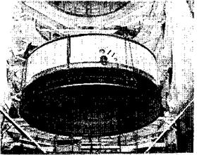
Michoud – The Michoud Assembly Facility is the fabrication site of the first stage booster. Dominating the skyline is the Vertical Assembly Building.

The plant is arranged for logical and efficient flow of materials from the loading dock through to final assembly. Paralleling the material flow are the rework and modification area and the test and laboratory areas. There are 50,000 square feet of tooling area in the plant.

image147

B-9847-7

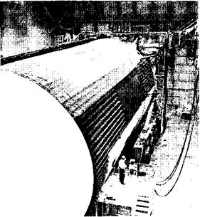
Stage Test—Before leaving Michoud, the completed booster undergoes a simulated firing during which all systems function in the Stage Test Building.

image148

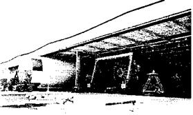
Barge Slip—First stages are loaded onto barges at Michoud and travel by waterways from New Orleans to Huntsville, Mississippi Test Facility, and Kennedy Space Center.

The environmentally controlled portion of the minor

assembly area contains facilities for heat treat­ment, chemical cleaning, conversion coating, and welding of pre-formed metal sections received at the loading dock. Final assembly of the propellant tanks and the joining of the major components into the complete stage occur in the Vertical Assembly Building (VABI.

The VAB is a single-story structure rising the equivalent of 18 stories. A 180-ton overhead crane is used to stack the five large cylindrical segments of the first stage into a vertical assembly position. A $50 million program included the construction of three buildings—the VAB, the Stage Test Building,

8-1

Подпись: S-27

Подпись: SATURN V NEWS REFERENCE
image150

Checkout of the stage’s electrical and mechanical systems is performed in the four giant test cells of the Stage Test Building. Each of the test cells-is 83 by 191 feet with 51 feet of clear height. Each has

separate test and checkout equipment.

Stages leave and enter Miehoud by waterways

connecting to the Mississippi River or the Gulf of Mexico.

image151

В-8Э30-10

Unique Vessels—Four of six special barges used to carry Saturn rocket stages are shown moored side-by-side at the Miehoud Assembly Facility. From left are the Little Lake, the Promise, the Poseidon, and the Palaemon.

NORTH AMERICAN SPACE DIVISION FACILITIES

The second stage of the Saturn V is manufactured and tested in facilities located from one end of the nation to the other.

The main fabrication and testing facilities are lo­cated in Seal Beach, Calif., about 15 miles south of Downey, which is the headquarters of SD opera­tions. SD subcontracts important elements of work to other North American facilities in Los Angeles and Tulsa and McAlester, Okla. The complex of buildings at Seal Beach, all built especially for the second stage, will be complemented by mid-1967 with three North American Aviation-owned build­ings which will house all the second stage admin­istrative, engineering, and support personnel who currently are located at Downey.

The Seal Beach facility includes a bulkhead fabri­cation building, 125-foot-high vertical assembly building, 116-foot-tall vertical checkout building, pneumatic test and packaging building, and a num­ber of other structures.

The bulkhead fabrication building is a large, highly specialized structure designed solely for the con­struction and assembly of the second stage’s three bulkheads. Among other tooling it contains an auto­clave about 40 feet in diameter with a 40-foot dome for curing the large stage bulkheads.

Over-all View—North American Sea! Beach facilities include in-process storage building (left); bulkhead fabrication building (center); vertical assembly building (far right); pneumatic test and packaging building (right center); and structural test tower (right front).

image152

S-28

Night firing of Test Second Stage at Santa Susana

image153

S-29

Space Truck Readied—The five engines of the Saturn V second stage dwarf technicians preparing the “battleship" vehicle for hot firing at North American’s Santa Susana static test lab.

8-2


image154

SATURN V NEWS REFERENCE

Подпись: 8-4

like conditions by being placed inside a 39-foot diameter vacuum chamber for extended periods of time. The chamber is capable of simulating the vacuum at an altitude of 500 miles above the earth. Structural tests on major vehicle structures such as the propellant tank, skirt sections, and interstage are conducted in the Structural Test Laboratory at the Space Systems Center.

Two vertical checkout towers at the Space Systems Center provide for the final factory tests on finished third stages, prior to shipment from the plant for test firing. The vertical checkout laboratory is equipped with two complete sets of automatic check­out equipment.

Actual ground test firings of the stages are accom­plished at the Douglas Sacramento Test Center, where each stage is delivered following the comple­tion of assembly and checkout at the Huntington Beach plant.

Primary Saturn facilities at Sacramento include a pair of 150-foot-high steel and concrete test stands where the stages are put through the final vehicle acceptance test—a full-duration, full-power static firing, simulating actual launch operations.

image155

DNRV-48

Static Test Firing of Third Stage at Sacramento

The Super Guppy, the world’s largest airplane, is the primary means of transporting the third stage from the Douglas Huntington Beach plant to the Sacramento Test Center, and from Sacramento to KSC. Developed by Aero Spacelines, Inc., for trans­port of large space hardware, the plane has an inside diameter of 25 feet and a total length of 141 feet. Tail height is 46 feet—almost five stories above the ground. Cubic displacement of the fuse­lage is 49,790 cubic feet, approximately five times
that of most present jet transports. The airplane is powered by four turbo-prop engines, producing a total of 28,000 horsepower.

image156

Super Guppy

H-5-29646

FUEL FEED SYSTEM

Ten fuel suction lines (two per engine) supply fuel from the fuel tank to the five F-l engines. The suc­tion line outlets attach directly to the F-l engine fuel pump inlets.

Each suction line has a pneumatically controlled fuel prevalve which normally remains open. This

image37Подпись:Подпись:image38"FUEL-CONDITIONING (BUBBLING) SYSTEM

The fuel-conditioning system bubbles gaseous ni­trogen through the fuel feed lines and fuel tank to prevent fuel temperature stratification prior to launch. A wire mesh filter in the nitrogen supply line prevents discharge of contaminants into the conditioning system.

image39

Fuel Conditioning

A check valve in the outlet of each fuel-conditioning line prevents fuel from entering the nitrogen lines when the fuel-conditioning system is not operating.

An orifice located near each fuel-conditioning check valve provides the proper nitrogen flow into each fuel duct.

Oxidizer Pump

The oxidizer pump supplies oxidizer to the thrust chamber and gas generator at a flowrate of 24.811 gpm. The pump consists of an inlet, an inducer, an impeller, a volute, bearings, seals, and spacers. Oxidizer is introduced into the pump through the inlet which is connected by duct to the oxidizer tank. The inducer in the inlet increases the pressure of the oxidizer as it passes into the impeller to pre­vent cavitation. The impeller accelerates the oxi­dizer to the desired pressure and discharges it through diametrically opposed outlets into the high-pressure oxidizer lines leading to the thrust chamber and gas generator.

The oxidizer inlet, which attaches to a duct leading to the vehicle oxidizer tank, is bolted to the oxi­dizer volute. Two piston rings seated between the inlet and the volute expand and contract with tem­perature changes to maintain an effective seal between the high and low pressure sides of the inlet. Holes in the low-pressure side of the inlet allow leakage past the ring seals to flow into the suction side of the inducer, thus maintaining a low – pressure.

The oxidizer volute is secured to the fuel volute with pins and bolts which prevent rotational and axial movement. The primary oxidizer seal and spacer located in the oxidizer volute prevent fuel from leaking into the primary oxidizer seal drain cavity. The oxidizer intermediate seal directs a purge

Подпись:Fuel Pump

The fuel pump supplies fuel to the thrust chamber and gas generator at a flowrate of 15,471 gpm. The pump consists of an inlet, an inducer, an impeller, a volute, bearings, seals, and spacers. Fuel is intro­duced into the pump from the vehicle fuel tank through the inlet. The inducer in the inlet increases the pressure of the fuel as it passes into the impeller to prevent cavitation. The impeller accelerates the fuel to the desired pressure and discharges it through two diametrically opposed outlets into the high-pressure fuel lines leading to the thrust chamber and gas generator.

The fuel volute is bolted to the inlet and to a ring, which is pinned to the oxidizer volute. A wear-ring installed on the volute mates against the impeller. The cavity formed between the volute and the impeller is called the balance cavity. Pressure in the balance cavity exerts a downward force against the fuel impeller and counterbalances the upward force of the oxidizer impeller to control the amount of shaft axial force applied to the No. 1 and No. 2 bearings. Leakage between the impeller inlet and the discharge is controlled by a wear-ring, which mates with the impeller and acts as an orifice. The fuel volute provides support for the bearing retainer, which supports the No. 1 and No. 2 bearings and houses the bearing heater. The No. 3 seal, which is installed between the oxidizer intermediate seal and the No. 1 bearing, prevents lubricating fuel for the bearings from contacting the oxidizer. If fuel should pass the seal, purge flow from the oxidizer intermediate seal will expel the fuel overboard. On the fuel side of the No. 2 bearing, the No. 4 lube seal contains the lubricant within the bearing cavity. The remaining seal in the fuel volute is the primary seal and contains fuel under pressure in the balance cavity, maintains the desired balance cavity pres­sure, and keeps high-pressure fuel out of the low – pressure side.

PROPELLANT SYSTEM

The propellant system is composed of seven sub­systems : purge, fill and replenish, venting, pres­surization, propellant feed, recirculation, and pro­pellant management..

Purge Subsystem

The purge subsystem uses helium gas to clear the propellant tanks of contaminants before they are loaded. The important contaminants art* oxygen in the liquid hydrogen tank (liquid hydrogen will freeze oxygen which is impact-sensitive) and moisture in the liquid oxygen tank.

The tanks are purged with helium gas from ground storage tanks. The tanks are alternately pressur­ized and vented to dilute the concentration of con­taminants. The operation is repeated until samples of the helium gas emptied from the tanks show that contaminants have been removed or reduced to a safe level.

Fill and Replenish Subsystem

Filling of the propellant tanks on the second stage is a complex and precise task because of the nature of thd cryogenic liquids and the construction of the stage.

Because the metal of the stage is at normal outside temperature, it must be chilled gradually before pumping the ultra-cold propellants into the tanks. The filling operation thus starts with the introduc­tion of cold gas into the tanks, lines, valves, and other components that will come into contact with the cryogenic fluids. The cold gas is circulated until

4.7

Подпись: SATURN V NEWS REFERENCE

image86"S-19

Channel Installed—Feed line from IH2 tank to one of the five engines is installed.

the metal has become chilled enough to begin pump­ing in the propellants. The filling and replenishing subsystem operation consists of five phases:

Chilldown – Propellants are first pumped into the tank at the rate of 500 gallons per minute for LQX and 1,000 gallons per minute for LHa. Despite the preliminary chilling by cold gas, the tanks are still so much warmer than the propellants that much of the latter boils off (converts to gaseous form) when it first goes into the tank. Filling con­tinues at this rate until enough of the propellants remain liquid so that the tanks are full to the five per cent level.

Fast Fill —As soon as tank sensors report that the liquid has reached the five per cent level, the fill­ing rate is increased to 5,000 gallons per minute for LOX and 10,000 gallons per minute for LH2. This rate continues until the liquid level in the tank reaches the 98 per cent level.

Slow-Fill—Propellant tanks are filled at the rate of 1,000 gallons per minute for both LOX and LH2 until the 100 per cent level is reached.

Replenishment—Because filling begins many hours before a scheduled liftoff and the cryogenic liquids are constantly boiling off, filling continues almost up to liftoff (160 seconds before liftoff for LOX and 70 seconds before liftoff for LH2). Tanks

are filled at the rate of up to 200 gallons per min­ute for LOX and up to 500 gallons per minute for LH,, depending on signals from sensors in the tanks on the liquid level.

101 Per Cent Shutdown—A sensor in each tank will send a signal to indicate that the 101 per cent level (over the proper fill level) has been reached; this signal causes immediate shutdown of filling operations.

Filling is accomplished through separate connec­tions, lines, and valves. The ground part of the con­nections is covered by special shrouds in which he­lium is circulated during filling operations. This provides an inert atmosphere around the coupling between the ground line and the tanks.

The coupling of the fill line and the tanks is engaged manually at the start of filling operations; it is nor­mally disengaged remotely by applying pneumatic pressure to the coupling lock and actuating a push – off mechanism. A backup method involves a remotely attached lanyard in which the vertical rise of the vehicle will unlock the coupling. The fill valves are designed so that loss of helium pressure or electrical power will automatically close them.

Liquid oxygen is the first propellant to be loaded onto the stage. It is pumped from ground storage tanks. Liquid hydrogen is transferred to the stage by pressurizing the ground storage tanks with gaseous hydrogen. The liquid hydrogen tank is chilled before the liquid oxygen is loaded to avoid structural stresses.

After filling is completed, the fill valves and the liquid oxygen debris valves in the coupling are closed, but the liquid hydrogen debris valve is left open. The liquid oxygen fill line is then drained and purged with helium. The liquid hydrogen line is purged up to the coupling. When a certain signal is received (first stage thrust-commit), the liquid hydrogen debris valve is closed and the coupling is separated from the stage.

The tanks can be drained by pressurizing them, opening the valves, and reversing the filling opera­tion.

RETROROCKET IGNITION SYSTEM

Four solid propellant retrorockets are mounted equidistant around the aft interstage assembly, and when ignited, assure clean separation of the third stage from the second stage by decelerating or braking the spent booster. Each retrorocket is rated for a nominal thrust of 35,000 pounds, weight of 384 pounds, and burn time of about 1.5 seconds.

image121

Retrorocket System

A signal from the second stage initiates two EBW firing units located on the aft interstage. The EBW firing units ignite two detonator manifolds, which in turn ignite the retrorockets through redundant pairs of confined detonating fuse (CDF) and py­rogen initiators.

Ullage Rocket System

ULLAGE CONTROL ROCKET IGNITION AND JETTISON SYSTEM

Two solid propellant ullage rockets, located on the third stage aft skirt just forward of the stage sepa­ration plane, are ignited on signal from the stage sequencer by EBW initiators.

After firing, the burned-out ullage rocket casings and fairings are jettisoned to reduce stage weight. Upon command from the stage sequencer, two forward and aft frangible nuts, which secure each rocket motor and its fairing to the stage, are det­onated by confined detonating fuse (CDF), to free the entire assembly from the vehicle.

IBM FACILITIES

Three IBM-owned buildings at Huntsville comprise the Space Systems Center where component test­ing, fabrication, assembly, and systems checkout of the instrument unit are completed. Assembly and the majority of the testing activity take place in a 130,000-square-foot building located in Hunts­ville’s Research Park.

As units are received, they are inspected and then moved to one of the testing laboratories where they are subjected to detailed quality and reliability testing. From component testing, the parts move

image157

IBM-DR-24

Ш Assembly and Test—All instrument unit assembly work and the majority of testing are done in this IBM-owned building in Huntsville’s Research Park. The rear of the building is the high – bay area where assembly operations take place.

Подпись:Following assembly operations, the IU is moved to one of two systems checkout stands—one for uprated Saturn I vehicles, the other for Saturn V.

image159

IBM-DR-25

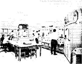
Automatic Checkout-IBM technicians monitor systems checkout tests as another technician optically adjusts the inertial guidance platform, prior to a simulated mission.

A complete systems checkout is performed auto­matically. Hooked by underground cables, two digital checkout computer systems examine the IU. Each of the IU’s six subsystems is tested before the IU is tested as an integrated unit. With indepen­dent computers, systems tests for two instrument units can be conducted simultaneously.

image160

IBMDR-26

Simulation Laboratory Saturn V flight guidance and navigation programs as well as launch computer programs are tested in IBM’s Engineering Building at Huntsville. Here a technician checks a computer readout of a simulated mission.

FUEL LEVEL SENSING AND ENGINE CUTOFF SYSTEMS

A cutoff sensor mounted on the bottom of the fuel tank provides signal voltages to shut off fuel after a predetermined level of depletion is reached. The fuel is measured during flight by four fuel slosh probes and a single liquid level measuring probe. Fuel levels are detected electronically and reported through the stage telemetry system. Telemetry

2-8
signals are transmitted to ground support either by radio frequency or, before launch, by coaxial cable. The cutoff sensor, mounted in the lower fuel tank bulkhead, initiates engine cutoff as fuel level falls below two sensing points on the probe. Engine cutoff will normally be initiated by sensors in the LOX system. The cutoff capability is provided as a backup system should fuel be depleted before LOX.

image40

Fuel Level Sensing and Engine Cutoff

FUEL PRESSURIZATION SYSTEM

The fuel pressurization system maintains enough pressure in the fuel tank to provide proper suction at the fuel turbopumps to start and operate en­gines. The system consists of a helium supply, a helium flow controller, helium fill and drain com­ponents, a prepressurization subsystem, a fuel tank vent and relief valve, and associated ducts.

Four 31-cubic-foot, high pressure storage bottles in the LOX tank store the helium required for in­flight pressurization of the fuel tank ullage. A high pressure line is used for filling the bottles and rout­ing the helium to the flow controller. A solenoid dump valve is installed for emergencies. The helium flow controller uses five solenoid valves mounted parallel in a manifold to control helium flow to the fuel tank ullage. The cold helium duct routes helium from the flow controller to the cold helium mani­fold. From there, it is distributed to the heat ex­changers on the five F-l engines. The hot helium manifold receives the heated, expanded helium from the engine heat exchangers and routes it to the hot helium duct which then carries it through the he­lium distributor and on to the fuel tank ullage.

image41

SATURN V NEWS REFERENCE

It is replenished between the periods of loading and prepressurization through the fill and drain line.

Before LOX drain can be performed, the helium cylinders in the LOX tank must have their pressure decreased from about 3,100 psig to about 1,660 psig. Fill and drain valves are opened to complete drainage of the LOX tank although total evacua­tion of LOX from the tank requires draining the engines or waiting for boil-off of residual LOX. LOX drain can be speeded with the aid of a pres­surizing gas, usually nitrogen.

Turbine

The turbine, producing 55,000 brake horsepower, drives the fuel and oxidizer pumps. It is a two-stage, velocity-compounded turbine consisting of two ro­tating impulse wheels separated by a set of stators. The turbine mounts on the fuel pump end of the turbopump so that the two elements of the turbo­pump having the greatest operating temperature extremes (1500 Fahrenheit for the turbine and -300

Hot gas from the gas generator enters the turbine at a flowrate of 170 pounds per second through the inlet manifold and is directed through the first-stage nozzle onto the 119-blade first-stage wheel. The hot gas then passes through the second-stage stators onto the 107-blade second-stage wheel, and then into the heat exchanger. This flow of hot gas rotates the turbine, which in turn rotates the propellant pumps. Turbine speed during mainstage operation is 5,550 rpm.

Bearing Coolant Control Valve

This valve, which incorporates three 40-micron fil­ters, three spring-loaded poppets, and a restrictor, performs two functions. Its primary function is to control the supply of coolant fuel to the turbopump bearings. Its secondary function is to provide a means of preserving the turbopump bearings be­tween static firings or during engine storage. During engine firing, the coolant poppet opens and delivers filtered fuel to the turbopump bearing coolant jets, and the restrictor provides the proper turbopump bearing jet pressure.

GAS GENERATOR SYSTEM

The gas generator system provides the hot gases for driving the velocity-compounded turbine, which drives the fuel and oxidizer pumps. The system con­sists of a gas generator valve, an injector, a com­bustion chamber, and propellant feed lines connect­ing the No. 2 turbopump fuel and oxidizer outlet lines to the gas generator. The propellants are supplied to the gas generator from the No. 2 turbo­pump fuel and oxidizer outlet lines. The gas genera­tor mixture ratio, relative to the engine mixture ratio, is fuel-rich. This provides a lower combustion temperature in the uncooled gas generator and in the turbine.

Propellants enter the gas generator through the valve and injector and are ignited in the combustion chamber by dual pyrotechnic igniters. The gas generator valve is hydraulically operated by fuel pressure from the hydraulic control system.

Venting Subsystem

The venting subsystem is used during loading and flight operations. While the propellant tanks are being loaded, the vent valves (two for each tank) are opened by electrical signals from ground equipment to allow the gas created by propellant boil-off to leave the tanks. The valves are spring-loaded to be normally closed, but a relief valve will open them if pressure in the tanks reaches an excessive level. Each valve is capable of venting enough gas to

4-8


image87

Подпись: SATURN V NEWS REFERENCE

The LH2 recirculation subsystem pumps the propel­lants through the feed lines and valves and back to the LIL tank through a single return line. The pumps are powered from a 56-volt DC battery sys­tem located in the interstage; the batteries are ejected with the interstage approximately 30 sec­onds after first plane separation. Refore liftoff, power for the LH2 recirculation subsystem is sup­plied by ground equipment.

The LOX recirculation system works on the basis of a thermal syphon; heat entering the system is used to provide pumping action by means of fluid density differences across the system. Helium gas is used to supplement the density differences and thereby improve the pumping action.

Recirculation of oxygen begins at the start of tank­ing; LIL recirculation begins just before launch. The propellants continue to circulate through first stage firing and up until just before the first stage and second stage separate. While the subsystems are operating, the LH2 prevalves which lead to the combustion chambers are closed; as soon as the re­circulation subsystem stops, the LH2 prevalves open and the engines ignite.

Propellant Management System

The propellant management system controls load­ing, flow rates, and measurement of the propel­lants. It includes propellant utilization, propellant loading, propellant mass indication, engine cutoff, and propellant level monitoring subsystems.

PROPELLANT UTILIZATION SUBSYSTEM

The propellant utilization subsystem controls the flow rates of liquid hydrogen and liquid oxygen in such a manner that both will be depleted simulta­neously. It controls the mixture ratio so as to min­imize propellant residuals (propellant left in the tanks) at engine cutoff. Propellant utilization bypass valves at the liquid oxygen turbopump outlets con­trol flow of liquid oxygen in relation to the liquid hydrogen remaining. Control of the engine mixture ratio increases the stage’s payload capability. The propellant utilization subsystem is interrelated with the propellant loading subsystem and uses some of the same tank sensors and ground checkout equip­ment.

PROPELLANT LOADING SUBSYSTEM

The loading subsystem is used to control propellant loading and maintain the quantity of propellants
in the tanks. Capacitance probes (sensors) running the full length of the propellant tanks sense liquid mass in the tanks and send signals to an airborne computer, which relays them to a ground computer to control loading. They also send signals to an airborne computer for the propellant utilization subsystem’s control of flow rates.

PROPELLANT MASS INDICATION SUBSYSTEM

The propellant mass indication subsystem is in­tegrated with the propellant loading subsystem and is used to send signals to the flight telemetry sys­tem for transmission to the ground. It utilizes pro­pellant loading sensors to determine propellant levels.

ENGINE CUTOFF SUBSYSTEM

The main function of the engine cutoff subsystem is to signal the depletion point of either propellant. It is an independent subsystem and consists of five sensors in each propellant tank and associated electronics. The sensors will initiate a signal to shut down the engines when two out of five sensors in the same tank signal that propellant is depleted.

RANGE SAFETY SYSTEM

The range safety system terminates vehicle flight upon command of the range safety officer. Redun­dant systems are used throughout to provide max­imum reliability.

Four antennas, mounted around the periphery of the third stage forward skirt assembly, feed two redundant secure range receivers located in the for­ward skirt assembly. Both receivers have separate power supplies and circuits. A unique combination of coded signals must be transmitted, received, and decoded to energize this destruct system.

A safety and arming device prevents inadvertent initiation of the explosive train by providing a posi­tive isolation of the EBW detonator and explosive train until arming is commanded. Visual and remote indications of SAFE and ARMED conditions are displayed at all times at the firing center. Upon proper command, EBW firing units activate EBW detonators.

A CDF, detonated by the safety and arming device, explodes a flexible linear-shaped charge which cuts through the tank skin to disperse both fuel and oxidizer.

RANGE SAFETY SYSTEM

5-13


I SATURN V NEWS REFERENCE

J-2 ENGINE FACT SHEET

image122

image123

R-16


LENGTH

WIDTH

NOZZLE EXIT DIAMETER THRUST (altitude)

SPECIFIC IMPULSE RATED RUN DURATION FLOWRATE: Oxidizer Fuel

MIXTURE RATIO CHAMBER PRESSURE (Pc)

WEIGHT, DRY, FLIGHT CONFIGURATION

EXPANSION AREA RATIO

COMBUSTION TEMPERATURE

Note: J-2 engines will be uprated to a maximum

11 ft. 1 in.

6 ft. SV2 in.

6 ft. 5 in.

225,0 lb.

424 sec. (427 at 5:1 mixture ratio)

500 sec.

449 lb sec (2,847 gpm)

81.7 lb sec (8,365 gpm)

5.5:1 oxidizer to fuel 763 psia 3,480 lb.

27.5:1

5,750°F

of 230,000 pounds of thrust for later vehicles.

Подпись: chamber throat and the exit at a pressure of more than 1,000 psi. In cooling the chamber the fuel makes a one-half pass downward through 180 tubes and is returned in a full pass up to the thrust chamber injector through 360 tubes. (See schematic drawing.) DOME The injector and oxidizer dome assembly is located at the top of the thrust chamber. The dome provides a manifold for the distribution of the liquid oxygen to the injector and serves as a mount for the gimbal bearing and the augmented spark igniter. THRUST CHAMBER INJECTOR The thrust chamber injector atomizes and mixes the propellants in a manner to produce the most efficient combustion. Six hundred and fourteen hollow' oxidizer posts are machined to form an integral part of the injector. Fuel nozzles are threaded and installed over the oxidizer posts forming concentric orifices. The injector face is porous and is formed from layers of stainless steel wire mesh and is welded at its periphery to the injector body. Each fuel nozzle is swaged to the face of the injector. The injector receives liquid oxygen through the dome manifold and injects it through the oxidizer posts into the combustion area of the thrust chamber. The fuel is received from the upper fuel manifold in the thrust chamber and injected through the fuel orifices which are concentric with the oxidizer orifices. The propellants are injected uniformly to ensure satisfactory combustion. GIMBAL The gimbal is a compact, highly loaded (20,000 psi) universal joint consisting of a spherical, socket- type bearing with a Teflon/fiberglass composition coating that provides a dry, low-friction bearing surface. It also includes a lateral adjustment device for aligning the chamber with the vehicle. The gimbal transmits the thrust from the injector assembly to the vehicle thrust structure and provides a pivot bearing for deflection of the thrust vector, thus providing flight attitude control of the vehicle. The gimbal is mounted on the top of the injector and oxidizer dome assembly. 6-і

I SATURN V NEWS REFERENCE