Category Apollo Saturn V News Reference

HOW SATURN V DESIGN WAS REACHED

While a major effort of this country’s space commit­ment was to explore the moon, the broader target was to build a capability—people, launch vehicles, propulsion, spacecraft, production, testing, and launching sites —to explore a vast new frontier and develop a long-range spacefaring capability that would establish continuing national preeminence.

The questions facing national space planners in 1961 and 1962 were complex. Although the use of a Saturn I for a manned lunar landing was theoreti­cally possible, it would have been extremely difficult. About six Saturn I launches would have been re­quired, their payloads being assembled in earth orbit to form a moon ship. No space rendezvous and docking had taken place at that time.

During the first half of 1962, two paramount de­cisions were announced: to develop a new general purpose launch vehicle in the middle range of sev­eral under consideration, and to conduct the manned lunar landing by use of a lunar orbit rendezvous (LOR) technique.

The Saturn V, as the chosen vehicle was named, was given the go-ahead in January, 1962.

It was to be composed of three propulsive stages and a small instrument unit to contain guidance and control. It could perform earth orbital missions through the use of the first two stages, while all three would be required for lunar and planetary ex­peditions. The ground stage was to be powered by five F-l engines, each developing 1.5 million pounds of thrust, and the stage would have five times the power of the Saturn I booster then under develop­ment. The upper stages would use the J-2 hydrogen/ oxygen engine, five in the second stage and one in the third. Each would develop up to 225,000 pounds of thrust. Such a rocket would be capable of placing 120 tons into earth orbit or dispatching 45 tons to the moon. (The numbers have been uprated now to about 125 and 47-1/2.)

During its assembly, checkout, and launch, the Saturn V7 would use a new mobile launch concept. It would be assembled in a huge Vehicle Assembly Building, and then transported in an upright posi­tion to a launch pad several miles away.

Propulsion development decisions preceded those for the vehicles.

The need for a building-block rocket engine in the million-pound-thrust class was apparent even as ARPA was ordering work to begin on the first stage cluster of engines for the Saturn I. In January, 1959, NASA contracted with North American Aviation’s Rocketdyne Division for development of the F-l.

Late in 1959, the Silverstein Committee recom­mended the development of a new high-thrust hydro­gen engine to meet upper stage requirements. In June, 1960, Rocketdyne was selected to develop the J-2 engine after evaluation of competitive proposals by NASA.

Three proposed Apollo modes which were considered in detail were: the direct flight mode, using a very large launch vehicle called "Nova”; the earth orbital rendezvous (EORI mode, requiring separate Saturn launches of a tanker and a manned spacecraft; and the lunar orbital rendezvous mode, requiring a single launch of the manned spacecraft and the lunar module.

Selected was the LOR mode, in which the injected spacecraft weight would be reduced from 150,000 pounds to approximately 80,000 pounds by eliminat­ing the requirement for the propulsion needed to soft-land the entire spacecraft on the lunar surface.

A small lunar excursion module, or LEM, now re­ferred to as the lunar module, would be detached after deboost into lunar orbit. The lunar module would carry two of the three-man Apollo crew to a soft landing on the moon and would subsequently be launched from the moon to rendezvous with the third crew member in the “mother ship.” The entire crew would then return to earth aboard the com­mand module.

NASA concluded that LOR offered the greatest assurance of successful accomplishment of the Apollo objectives at the earliest practical date.

Members of NASA’s Manned Space Flight Man­agement Council recommended LOR unanimously in 1962 because it:

1. Provided a higher probability of mission suc­cess with essentially equal mission safety;

2. Promised mission success some months earlier than did other modes;

3. Would cost 10 to 15 per cent less than the other modes; and

4. Required the least amount of technical develop­ment beyond existing commitments while ad­vancing significantly the national technology.

As a part of the Saturn V decision, it was deter-

1-5

Подпись: SATURN V NEWS REFERENCE

mined that elements of the existing Saturn I ve­hicle and the planned Saturn V would be combined to form a new mid-range vehicle, the uprated Saturn I (Saturn IB), The Uprated Saturn I would have a payload capability 50 per cent greater than the Saturn I and would make possible the testing of the Apollo spacecraft in earth orbit about one year earlier than would be possible with the Saturn V.

By the end of 1962, all elements of the new pro­gram were under way, with the Marshall Space Flight Center directing the work for NASA. The Boeing Company; Space Division of North Amer­ican Aviation, Inc.; and Douglas Aircraft Company were acting as prime contractors for the Saturn V first, second, and third stages, respectively. Engines were being developed by the Rocketdyne Division of North American. MSFC designed the instrument unit and awarded a production contract to Inter­national Business Machines Corp. (Chrysler Corp. had been selected to produce the first stage of the Uprated Saturn I.)

A large network of production, assembly, testing, and launch facilities was also being prepared by the end of 1962. Aside from the provision of various facilities at contractor plants and the augmentation of the Marshall Space Flight Center resources, three new government operations were established: the launch complex in Florida operated by the NASA – Kennedy Space Center and two new elements of MSFC—Michoud Assembly Facility in New Orleans, La., for the production of boosters, and Mississippi Test Facility, Bay St. Louis, Miss., for captive firing of stages.

Four years after its establishment, the Saturn V program was progressing on schedule, pointing toward the launch of the first vehicle in 1967 and fulfillment of the manned lunar landing before the end of the decade.

PROGRAM HIGHLIGHTS

Following are highlights of the Saturn V develop­ment program:

1961

Aug. 24 NASA announced the selection of the 88,000-acre site at Merritt Island, Fla., adjacent to Kennedy Space Center, then Cape Canaveral, for the assembly, check­out, and launch of the Saturn V.

Sept. 7 NASA selected the government-owned Michoud plant, New Orleans, as production site for Saturn boosters. It became a part of the Marshall Space Flight Center.

Sept. 11 NASA selected North American Aviation, Inc., to develop and build the second stage
for an advanced Saturn launch vehicle (as yet undefined) for manned and unmanned missions. One month later the Marshall Center directed NAA to design the second stage using five J-2 engines. A prelimi­nary contract was signed in February, 1962.

Oct. 6 NASA selected the Picayune-Bay St. Louis, Miss., area for its Mississippi Test Facility — an arm of the Marshall Center —for use in static testing of rocket stages and en­gines.

Dec. 15 The Boeing Company was selected as prime contractor for the first stage of the ad­vanced Saturn vehicle —not yet fully de­fined. A preliminary contract was signed in February, 1962, with the work to be con­ducted at the Michoud Assembly Facility.

Dec. 21 NASA selected the Douglas Aircraft Com­pany to negotiate a contract to develop the third stage (S-IVB) of the advanced Saturn, based on the Saturn I’s S-IV stage. A sup­plemental contract for production of 11 third stages was signed in August, 1962.

1962

Jan. 10 Announcement was made that the advanced Saturn vehicle would have a first stage powered by five F-l engines, a second stage powered by five J-2 engines, and for lunar missions a third stage with one J-2 engine.

Jan. 25 NASA formally assigned development of the three-stage Saturn C-5 (Saturn V be­came the name in February, 1963) to MSFC.

April 11 NASA Headquarters gave the Apollo/ Saturn I/Saturn V highest national priority.

May 26 Rocketdyne Division of NAA conducted the first full-thrust, long-duration F-l en­gine test.

July 11 It was announced that the Saturn IB (Up­rated Saturn I) would be developed and that the lunar orbit rendezvous method of accomplishing a lunar landing had been selected.

Decern – The U. S. Army Corps of Engineers

ber awarded a contract for the design of the Vehicle Assembly Building (VAB) at the Florida launch complex.

1963

Feb. 27 The first contract for the Mississippi Test Facility (MTF) Saturn V test facilities was awarded.

May The J-2 engine was successfully fired for the first time in a simulated space altitude of 60,000 feet.

Подпись: i-6

Oct. 31 The Marshall Center received the first production model of the F-l engine.

Подпись: SATURN V NEWS REFERENCE

Nov. 12 NASA contracted for the first Saturn V launch pad at the Kennedy Space Center.

1964

March IBM was awarded an instrument unit con­tract for the digital computer and data adapter by the Marshall Center. IBM be­came the prime IU contractor in May.

Oct. 9 The Edwards AFB test facility was ac­cepted as the F-l test complex, amounting to a cost of $34 million.

Dec. 1 The first mainstage shakedown firing of the third stage battleship was accomplish­ed, lasting 10 seconds.

Dec. 23 First full-duration firing of the third stage battleship occurred.

1965

April 16 All five engines of the S-IC-T, first stage test vehicle, were fired at the Marshall Center for 6.5 seconds.

April 24 The first cluster ignition test of the second stage battleship was successfully com­pleted.

Aug. 5 The first full-duration firing of the first

stage was conducted successfully at the Marshall Center.

Aug. 8 Third stage flight readiness test of 452 seconds, fully automated, was accomplish­ed at Sacramento.

Aug. 13 The IU was qualified structurally and man­
rated for Saturn V use by withstanding a 140 per cent load limit.

Aug. 17 The third stage battleship was tested in Saturn V configuration for full duration (start-stop-restart).

Dee. 16 The S-IC-T static firings were completed at the Marshall Center with a total of 15 firings—three of full duration.

1966

Feb. 17 The S-IC-1 underwent static firing at the

& 25 Marshall Center and required no more static firings.

Mar. 30 The S-IU-500F was mated to the three stages of the Saturn V facilities vehicle at the Kennedy Space Center’s VAB.

May 20 First full-duration firing of the second stage flight stage was conducted at MTF.

May 25 The Apollo/Saturn V facilities vehicle, AS – 50Q-F, was transported to Pad A at Launch Complex 39, KSC, on the crawler.

May 26 Full-duration acceptance firing of the S – IVB-501, the first flight version of the third stage for Saturn V, was accomplished.

Septem – The F-l and J-2 engines were qualified for

ber manned flights.

Dec. 1 Initial static firing of the first flight ver­sion of the second stage occurred at MTF.

Nov. 15 The first flight version of the first stage was static fired at MSFC.

image12

1-7


j| SATURN V NEWS REFERENCE

FIRST STAGE FACT SHEET

33′

image13

WEIGHT: 300,000 lb. (dry)

4,792,0 lb. (loaded)

DIAMETER: 33 ft.

HEIGHT: 138 ft.

BURN TIME: About 2.5 min.

VELOCITY: 6,000 miles per hour at burnout (approx.)

ALTITUDE AT BURNOUT: About 38 miles

MAJOR STRUCTURAL COMPONENTS

THRUST STRUCTURE FUEL TANK INTERTANK LOX TANK FORWARD SKIRT

MAJOR SYSTEMS

PROPULSION: Five bipropellant F-l engines Total thrust: 7.5 million lb.

Propellant: RP-1- 203,000 gal. or 1,359,000 lb.

LOX—331,000 gal or 3,133,000 lb.

Pressure: Control 1.27 cubic feet of gaseous nitrogen at 3,250 psig

Fuel pressurization – 124 cubic feet or 636 lb. of gaseous helium at 3,100 psig LOX pressurization gaseous oxygen converted from 6,340 pounds of LOX by the engines HYDRAULIC: Power primarily for engine start and for gimbaling four outboard engines ELECTRICAL: Two 28 VDC batteries, basic power for all electrical functions INSTRUMENTATION: Handles approx. 900 measurements TRACKING: ODOP Transponder

і SATURN V NEWS REFERENCE

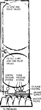
GROUND CONTROL PRESSURE SYSTEM

The ground control pressure system provides a direct ground pressure supply for some of the first stage pneumatically actuated valves. The valves are involved with propellant fill and drain and emer­gency engine shutdown system operations. Direct ground control assures a backup system in case of emergency and conserves the onboard nitrogen supply.

ONBOARD PURGE PRESSURE SYSTEM

The onboard purge pressure system consists of three high-pressure nitrogen storage bottles iden­tical to the onboard control pressure storage bottle, an umbilical coupling and tubing for filling the bot­tles, and a manifold assembly and tubing for re­ceiving and delivering the gas to the engine and calorimeter purge systems. These purge systems expel propellant leakage and are necessary from the time of loading throughout flight.

Environmental Control System

The environmental control system protects stage equipment from temperature extremes in both the forward skirt and thrust structure areas and pro­vides a nitrogen purge during prefiring and firing

operations. INSTRUMENTATION

CANISTERS

image53

Temperature-controlled air is provided by a ground air conditioning unit from approximately 14 hours before launch to approximately 6 hours before launch. At this time, gaseous nitrogen from an auxiliary nitrogen supply unit is introduced into the system and used to purge and condition the for­ward skirt and thrust structure areas until umbilical disconnect at launch.

A distribution manifold vents air and gaseous ni­trogen through orifices into the thrust structure to maintain proper temperature. Air and nitrogen are supplied from the ground.

The system also distributes air and gaseous nitro­gen to instrumentation canisters mounted in the forward skirt. Temperatures in the canisters are held to meet requirements of electrical equipment. From the canisters, the conditioning gas is vented into the forward skirt compartment.

Visual Instrumentation

Visual instrumentation, presently planned to be installed on two flight stages, is designed to monitor critical stage functions prior to and during static test and flight conditions.

ENGINE CUTOFF

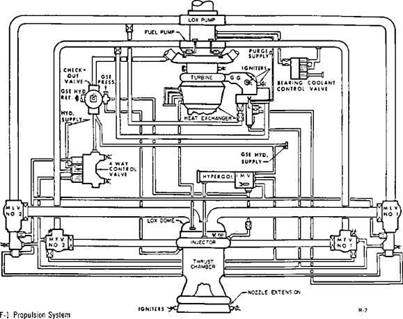
When the cutoff signal is initiated, the LOX dome operational oxidizer purge comes on. and the en­gine control valve stop solenoid is energized. Hy­draulic pressure holding open the gas generator valves, the oxidizer valves, and the fuel valves is routed to return. Simultaneously, hydraulic pres­sure is directed to the closing ports of the gas gen­erator valve, the oxidizer valves, and the fuel valves. The checkout valve is actuated and, as propellant pressures decay, the high level oxidizer purge be­gins to flow: then the igniter fuel valve and the igni­tion monitor valve close. Thrust chamber pressure will reach the zero level at about the same time the oxidizer valves reach full-closed.

3-10


image69

WEIGHT: 95,000 lb. (dry)

1,037,0 lb. (loaded)

DIAMETER: 33 ft.

HEIGHT: 81 ft. 7 in.

BURN TIME: 6 min. approx, (actually 395 sec.)

VELOCITY: 15,300 miles per hour at burnout (approx.)

ALTITUDE AT BURNOUT: 114.5 miles

MAJOR STRUCTURAL COMPONENTS

AFT INTERSTAGE THRUST STRUCTURE COMMON BULKHEAD LH2 FORWARD BULKHEAD

AFT SKIRT AFT LOX BULKHEAD LH2 CYLINDER WALLS FORWARD SKIRT

MAJOR SYSTEMS PROPULSION: Five J-2 engines

Thrust: More than 1,000,000 lb. (225,000 maximum each engine)

Propellant: LH2~-260,000 gal. (153,000 lb.)

LOX 83,000 gal. (789,000 lb.)

ELECTRICAL: 6 electrical bus systems, four 28-volt DC flight batteries, and motor-operated power transfer switches ORDNANCE: Provides, in operational sequence, ignition of eight ullage motors before ignition of five main engines, explosive separation of second stage interstage skirt, explosive separation of second stage from third stage, and ignition of four retrorockets to decelerate second stage for complete separation MEASUREMENT: Instrumentation, telemetry, and radio frequency subsystems THERMAL CONTROL: A ground-operated system that provides proper temperature control for equipment containers in the forward and aft skirt FLIGHT CONTROL: Gimbaling of the four outboard J-2 engines as required for thrust vector

control, accomplished by hydraulic-powered actuators which are electrically controlled from signals initiated in the flight control computer of the instrument unit (atop the Saturn V third stage)

і SATURN V NEWS REFERENCE

PNEUMATIC CONTROL SYSTEM

The pneumatic control system provides GHe (gas­eous helium) pressure to operate all third stage pneumatically operated valves with the exception of those provided as components of the J-2 engine. GHe is supplied from an ambient helium sphere and pressurized from a ground source before propel­lant fill operations at 3,100 ± 100 psia at 70° Fahren­heit for valve operation. The sphere is located on the thrust structure and is pre-conditioned to above 70° Fahrenheit from the environmental control system before liftoff.

The pneumatic control system provides regulated pressure at 475 ± 25 psig for operation of the LH, and LOX vent-relief valves during propellant load­ing, LH2 directional control valve, LOX and LH, fill and drain valves during loading, and the GH2 engine start system vent-relief valve. It also pro­vides operating pressures for the LH, and LOX turbopump turbine purge module, LOX chilldown pump purge module control, LOX and LH, pre­valves, LOX and LH, chilldown shutoff valves, and the LH, continuous propulsive vent control module.

The pneumatic control subsystem is protected from overpressure by a normally open solenoid valve controlled by a downstream pressure-sensing switch. At pressures greater than 535 + 15, -10 psia, the pressure switch actuates and closes the valve. At pressures below 450 + 15, -10 psia, the pressure switch drops out and the solenoid opens, thus acting as a backup regulator.

ENGINE RESTART

To provide third stage restart capability for the Saturn V, the J-2 gaseous hydrogen start tank is refilled in 60 seconds during the previous firing after the engine has reached steady-state operation. (Refill of the gaseous helium tank is not required because the original ground-fill supply is sufficient for three starts.) Prior to engine restart, the stage ullage rockets are fired to settle the propellants in the stage propellant tanks, ensuring a liquid head to the turbopump inlets.

Also, the engine propellant bleed valves are opened, the stage recirculation valve is opened, the stage prevalve is closed, and a LOX and LH2 circulation is effected through the engine bleed system for five minutes to condition the engine to the proper temperature to ensure proper engine operation.

Engine restart is initiated after the “engine ready" signal is received from the stage. This is similar to the initial “engine ready". The hold time between cutoff and restart is from a minimum of 1-1/2 hours to a maximum of 6 hours, depending upon the num­ber of earth orbits required to attain the lunar window for translunar trajectory.

^ SATURN V NEWS REFERENCE

Transporter

The capacity to transport the massive mobile launcher with a fully erected Saturn V in launch ready condition is a key to the mobile concept of Launch Complex 39. This is accomplished by a huge transporter which moves the mobile launcher and vehicle from the VAB to the launch site, approx­imately 3.5 miles away. The transporter moves at a maximum speed of 1 mile per hour, loaded, or 2 miles per hour, unloaded. The vehicle —131 feet long and 114 feet wide—moves on four double­tracked units, each 10 feet high and 40 feet long. Each unit is driven by an electric motor.

Tractive power is provided by 16 direct current motors served by two diesel-driven direct current generators. The generators are rated at 1,000 kilo­watts each and are driven by 2,750 horsepower diesel engines. Speed of the vehicle is controlled by – varying the generator fields. Power for the fields is provided by two 750-kilowatt power units which also provide power for pumps, lights, instrumenta­tion, and communications.

Подпись:Подпись: K-107-66PC-87 Facility Vehicle at Ramp of Launch Pad

MOBILE SERVICE STRUCTURE

External access to the Saturn V space vehicle at the launch site is provided by the mobile service structure. The steel-truss structure rises more than 400 feet above ground level and more than 350 feet above the deck of the mobile launcher. It has five platforms which close around the vehicle. Two platforms are powered to move up and down. The remaining three are relocatable, but not self­powered. A mechanical equipment room, opera-

8- 14
tions support room, communications and television equipment room, and various other equipment com­partments are located in the base.

The service structure is moved to and from the pad by the transporter. Once in position, either at the launch pad or in a parking area, the structure is anchored to support pedestals. The service struc­ture remains in position at the pad until about T-7 hours when it is removed to its parking area 7,000 feet from the pad.

FIRST STAGE

FIRST STAGE DESCRIPTION

The Saturn V first stage (S-IC) is a vertical group­ing of five cylindrical major components and a cluster of five F-l rocket engines. Upward from the engines are the thrust structure, fuel tank, inter­tank structure, LOX tank, and forward skirt. The total stage measures 138 feet in height and 33 feet in diameter without its fins. It weighs 6,100,000 pounds at liftoff and delivers 7.5 million pounds of thrust.

image14

FIRST STAGE FABRICATION AND ASSEMBLY

Design, assembly, and test of the first stage booster are the prime tasks being performed by The Boeing Company at the Marshall Space Flight Center, Huntsville, Ala., the Michoud Assembly Facility, New Orleans, La., and the Mississippi Test Facility in southwestern Mississippi. Launch operations support is provided by the Boeing Atlantic Test

Center, Kennedy Space Center, Fla. Contractor suppliers lend support for much of the first stage fabrication. Several ground test stages were com­pleted before manufacture of a series of flight stages was begun. Huntsville and Michoud installations shared responsibility for assembly of four ground test stages and the first two flight stages. All other flight stages are being assembled at Michoud.

image15

B-7031-10

Assembled First Stage

Thrust Structure

The thrust structure is the heaviest of first stage components, weighing 24 tons. It is 33 feet in diam-

image16

B-10648-5

Base Assembly—Workmen cover the thrust structure shell with aluminum skin.

2-1


SATURN V NEWS REFERENCE

Подпись: 2-2

eter and about 20 feet tall with these major com­ponents: the lower thrust ring assembly, the center engine support assembly, four holddown posts, en­gine thrust posts, an upper thrust ring assembly, intermediate rings, and skin panel assemblies.

The upper ring provides stability for the corrugated skins around the structure. Four F-l engines are mounted circumferentially upon the thrust posts and the fifth upon the center engine support assem­bly. The center engine remains rigid while the others gimbal or swivel, allowing the stage to be guided.

A base heat shield protects internal parts from en­gine heat, and four holddown posts restrain the vehicle while the engines build up power for liftoff.

The thrust structure supports the entire vehicle weight and distributes the forces of the engines.

image17

B-6018-7

Thrust Structure—The 24-ton base of the booster is being taken to the Vertical Assembly Building for mating with other first stage components.

Fuel Tank

The fuel tank holds 203,000 gallons of kerosene and encloses a system of five LOX tunnels.

The tank, weighing more than 12 tons dry, is cap­able of releasing 1,350 gallons of kerosene per sec­ond to the engines through 10 fuel-suction lines. The LOX tunnels carry liquid oxygen from the LOX tank, through the fuel tank, and to the engines.

Bound by eight aluminum skin panels, the fusion – welded fuel tank assembly is 33 feet in diameter and 44 feet tall. Ends are enclosed by ellipsoidal bulkheads.

The bulkheads consist of eight pie-shaped gores mated with a polar cap to form a dome shape.

Connecting links between the skin rings and bulk­heads are circular bands known as the Y-rings. The Y-rings are used on both propellant tanks and link them to other segments of the booster at final

assembly.

image18

В-*>4Ь9-20

Fuel Tank—Kerosene is fed to the engines at 1,300 gallons per second from this 203,000 gallon tank. Here the finished tank is being lowered onto its transporter.

image19

B-5622-4

Inside View—The fuel tank contains horizontal baffles, which are designed to prevent sloshing of fuel.

image20

B-4780-6

Fuel Tank Assembly – Workmen weld the base of the 27-inch – high Y-ring to the cylindrical segment of the fuel tank. This ring joins the tank sides to the dome and to the intertank structure.

FILM CAMERAS

Подпись: 2-15

The first stage film cameras provide photographic coverage of the LOX tank interior during launch, flight, and separation. The stage carries four film cameras. The two LOX-viewing cameras will pro­vide color motion pictures to show the following: behavior of the liquid oxygen, possible wave or slosh motions, and cascading or waterfall effects of the liquid from the internal tank structure. The capsules, which contain the cameras, are ejected automatically about 25 seconds after separation and are recovered after descent into the water. First stage flight versions of the camera consist of the LOX tank-viewing configuration plus two direct-viewing stage separation capsules. The in­stallation is in the forward skirt area. The tank­viewing optical lenses and the two strobe flash light assemblies are mounted in the LOX tank manhole covers. Connecting the remotely located camera capsules and the flash head are the optical assemblies, consisting of coupling lens attached to the ejection tube, a 9-foot length of fiber optics, and the objec­tive lens mounted in the flash-head assembly. The equipment required to complete the system, such as batteries, power supplies, timer, and synchroniz­ing circuitry, is contained in the environmentally controlled equipment racks or boxes mounted around the interior of the forward skirt structure. The combined timer and synchronizing unit serves

Подпись: The television system on the first stage will transmit four views of engine operation and other engine area functions in the interval from fueling to first

image55

two functions. The digital pulse timer supplies real time correlation pulses which are printed on one edge of the film. The timer also supplies event marker pulses to the opposite edge of the film to record selected significant events such as liftoff, engine shutdown, and stage separation. The syn­chronizing unit times the intermittent illumination provided by the strobe lamps to coincide with the open portion of the rotating shutter as it passes the motion picture film gate. The capsule assembly consists of the heavy nose section and quartz win­dow, which protect the capsule during re-entry heating and impact on the water. The body of the capsule, including the camera, is sealed and water­tight. A paraloon and drag skirt aid its descent and flotation. A radio beacon and flashing light are mounted on the capsule to aid in recovery.

TELEVISION SYSTEM
stage separation. The system utilizes two split fiber optics viewing systems and two cameras. Ex­tremes in radiant heat, acoustics, and vibration prohibit the installation of the cameras in the en­gine area; therefore, fiber optics bundles are used to transmit the images to the cameras located in the thrust structure. Quartz windows are used to pro­tect the lens. Both nitrogen purging and a wiping action are used to prevent soot buildup on the pro­tective window.

Image enhancement improves the fiber-optical sys­tems by reducing the effects of voids between fibers and broken fibers. An optically flat disc with paral­lel surfaces rotates behind each objective lens.

The drive motor rotates in synchronism with the master drive motor. A DC to AC inverter energizes the synchronous drive motors. A camera control unit houses amplifiers, fly back, sweep, and other circuits required for the video system. Each vidicon output (30 frames/second) is amplified and sampled every other frame (15 frames/second) by the video register. A 2.5 watt FM transmitter feeds the 7- element yagi antenna array covered by a radome.

SECOND STAGE

SECOND STAGE DESCRIPTION

The second stage of the Saturn V is the most power­ful hydrogen-fueled launch vehicle under produc­tion. Manufactured and assembled by North Amer­ican Aviation’s Space Division, it employs the cryogenic (ultra-low temperature) propellants of liquid hydrogen and liquid oxygen, which must be contained at temperatures of -423 and -297 degrees Fahrenheit, respectively.

For the lunar mission, the second stage takes over from the Saturn V’s first stage at an altitude of approximately 200,000 feet (38 miles) and boosts its payload of the third stage and Apollo space­craft to approximately 606,000 feet (114.5 miles). When its five J-2 engines ignite, the stage is pushing more than one million pounds, a load greater than that of any U. S. booster prior to the Saturn pro­gram. Speed of the stage ranges from 6,000 miles per hour to 15,300 miles per hour.

The beginning of second stage boost is a two-step process. Wien all the F-l engines of the first stage have cut off, the first stage separates. Eight ullage rocket motors located around the bottom of the second stage then fire for approximately 4 seconds to give positive acceleration to the stage prior to ignition of the five J-2 engines. About 30 seconds after the first stage separation, the part of the second stage structure on which the ullage rockets

image70

Mating—A completed second stage is mated to a first stage at Kennedy Space Center, Fla. This particular stage was used for facilities checkout.

are located (the aft interstage) is separated by firing explosive charges. This second separation is a precise maneuver: the 18-foot-high interstage must slip past the engines without touching them. With the stage traveling at great speed, the inter­stage must clear the engines by only a little more than 3 feet.

The second stage burns for about 6 minutes, push­ing its payload into space. At the end of boost, all J-2 engines cut off at once, the stages separate, and the J-2 engine on the third stage begins firing to take it and the Apollo spacecraft into a parking earth orbit. The 81-foot 7-inch second stage is basically a container for its 942,000 pounds of pro­pellant with engines attached at the bottom. Pro­pellants represent more than 90 per cent of the stage’s total weight. Despite this great weight of propellant and the stresses the stage must take during launch and boost, the stage is primarily without an internal framework. It is constructed mostly of lightweight aluminum alloys ribbed in such a fashion that it is rigid enough to withstand the pressures to which it is subjected. Special lightweight insulation had to be developed to kc p its cryogenic propellants from warming and thus turning to gas and becoming totally useless as propellant. The insulation that helps maintain a difference of about 500 degrees between outside (70 to 80-degree normal Florida temperature) and inside (-423° F of liquid hydrogen) is only about 1-1/2 inches thick around the hydrogen tank.

A unique feature of the second stage is its common bulkhead, a single structure which is both the top of the liquid oxygen tank and the bottom of the liquid hydrogen tank. This bulkhead was a critical item in the development of the stage. The relatively thin bulkhead, consisting of two aluminum facing sheets separated by a phenolic honeycomb core insulation, must maintain a temperature difference of 126 degrees between the two sides. The insulation which accomplishes this varies from one-tenth of an inch thickness at the girth to 4-3/4 inches thickness at the apex of the bulkhead. Development of the com­mon bulkhead resulted in a weight saving of appox – imately 4 tons and more than 10 feet in stage length.

Filght Control System

The flight control system provides stage thrust vector steering and attitude control. Steering is achieved by gimbaling the J-2 engine during pow-

Filght Control System

5-8


SATURN V NEWS

ered flight. Hydraulic actuator assemblies provide J-2 engine deflection rates proportional to steering signal corrections supplied by the IU.

image111

Stage roll attitude during powered flight is con­trolled by firing the APS attitude control engines.