SATURN V NEWS REFERENCE
Heat exchanger LOX inlet temperature Heat exchanger GOX outlet temperature Heat exchanger helium outlet temperature Fuel pump inlet No. 2 temperature Heat exchanger LOX inlet flowrate
Primary and Auxiliary Junction Box
There are two electrical junction boxes in the flight instrumentation system. The primary junction box has provisions for eight electrical connectors, and the auxiliary junction box for five. Both junction boxes are welded closed and pressurized with an inert gas to prevent possible entry of contaminants and moisture.
ENGINE OPERATION
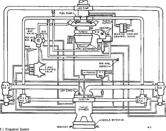
The engine requires a source of pneumatic pressure, electrical power, and propellants for sustained engine operation. A ground hydraulic pressure source, thrust chamber prefill, gas generator and turbine exhaust igniters, and hypergolic fluid are required to start the engine.
When the start button is actuated, the checkout valve moves to transfer the hydraulic fuel return from the ground line to the turbopump low-pressure fuel inlet. The high-level oxidizer purge is initiated to the gas generator and thrust chamber LOX dome.
The gas generator and turbine exhaust gas igniters fire, and the engine control valve start solenoid is energized. Hydraulic pressure is directed to the opening port of the oxidizer valves. The oxidizer valves are part way open, and the hydraulic pressure is directed to the gas generator valve opening port. The gas generator valve opens, propellants under tank pressure enter the gas generator combustion chamber, and the propellant mixture is ignited by the gas generator igniters. The exhaust gas is ducted through the turbopump turbine, the heat exchanger, and the thrust chamber exhaust manifold into the nozzle extension walls where the fuel-rich mixture is ignited by the turbine exhaust gas igniters. As the turbine accelerates the fuel and the oxidizer pumps, the pump discharge pressures increase and propellants at increasing flowrates are supplied to the gas generator. Turbopump acceler-
|
SATURN V NEWS REFERENCE
ation continues and, as the fuel pressure increases, the igniter fuel valve opens and allows fuel pressure to huild up against the hypergol cartridge hurst diaphragm. The hypergol diaphragms burst under the increasing fuel pressure. Hypergolic fluid, followed by the ignition fuel, enters the thrust chamber. When hypergolic fluid enters the thrust chamber and contacts the oxidizer, spontaneous combustion occurs, establishing thrust chamber ignition. Thrust chamber pressure is transmitted through the sense line to the diaphragm of the ignition monitor valve. When the thrust chamber pressure increases, the ignition monitor valve actuates and allows hydraulic fluid flow to the opening port of the fuel valves. The fuel valves open and fuel is admitted to the thrust chamber.
Fuel enters the thrust chamber fuel inlet manifold and passes through the thrust chamber tubes for cooling purposes and then through the injector into the thrust chamber combustion zone. As the thrust chamber pressure increases, the thrust-OK pressure switches are actuated indicating the engine is operating satisfactorily. The thrust chamber pressure continues to increase until the gas generator reaches rated power, controlled by orifices in the propellant lines feeding the gas generator. When engine fuel pressure increases above the ground-
supplied hydraulic pressure, the hydraulic pressure supply source is transferred to the engine. Hydraulic fuel is circulated through the engine components and then returned through the engine control valve and checkout valve into the turbopump fuel inlet. The ground hydraulic source facility shutoff valve is actuated to the closed position when the fuel valves open. This allows the engine hydraulic system to supply the hydraulic pressure during the cutoff sequence.


