Category A VERTICAL EMPIRE

BK11

Single stage. Launched 17 October 1963. Apogee 322 miles.

This was launched in support of the ELDO programme, and was designed to test the safety systems and the broadband telemetry. The interim report issued after the flight had this to say:

Two WREBUS [Weapons Research Establishment Break Up System] command destruct systems were tested with a comprehensive programme during the whole of the flight. One WREBUS system was commanded by a transmitter located at Red Lake, and the other by a temporary low-power installation at the rangehead. The test programme featured both manual and automatic command functions.

… During the whole of the flight the broadband telemetry system… functioned well and records of equipment monitoring were obtained.4

A second vehicle, BK10, was in reserve in case the tests had to be repeated. Since the flight had met all its objectives, BK10 was never fired and is now in the World Museum, Liverpool.

BK11

BK11

Figure 99. The re-entry heads of Project Dazzle.


Подпись:The final six Black Knight launches were part of Project Dazzle, and the various re-entry heads can be seen in Figure 99 above. The range instrumentation was greatly improved, as can be seen in the pictures above.5 The purpose of these flights was to study re­entry phenomena more closely. Dazzle was a joint UK/US/Australian project – the UK providing the vehicles and re-entry heads, Australia supplying the range facilities, and the US supplying much of the instrumentation.

A Black Knight IRBM

One rather unusual proposal surfaced at the time when Skybolt was cancelled. At the subsequent Nassau conference in December 1962, Macmillan was able to persuade President Kennedy to provide Polaris, effectively without strings. This seemed to be distinctly improbable at the outset, and there was obviously a short period of almost panic in the British delegation. Without Skybolt and without Polaris, Britain would have been thrown back entirely on its own resources, which were then very few. Sir James Lighthill, at that time Director of RAE, came up with a proposal for a missile based on Black Knight and wrote a note for Macmillan headed ‘A Possible British Deterrent’. It begins by saying:

Advances in technology make it possible, today, to do Blue Streak’s job with a rocket at one tenth of Blue Streak’s weight. The main advances have been in reduction of weight of warhead, and the perfection of the technique of the two-stage rocket, whose first stage is shed after it has burnt itself out.1

He then put forward the idea that:

… The very successful research vehicle BLACK KNIGHT (an entirely British development began in 1956 as a ‘lead into’ BLUE STREAK and first fired 2U years later) could now do the job with a small second stage. Several two stage rockets with BLACK KNIGHT as first stage have actually been fired. In the last three firings, all systems (including first and second stage separation, and complex data processing and transmission systems) worked as planned. In all fourteen firings of BLACK KNIGHT, the first stage flew successfully.

For delivery of nuclear warheads over 1500 nautical miles (the London Moscow distance), a suitable second stage would be one using the extremely well tried Gamma 201 engine (of 4000 pound thrust). Guidance would be based on the Ferranti miniature stable platform, of which the prototype has already been satisfactorily tested.

The fuels would be kerosene and hydrogen peroxide (which can be stored at room temperature for a whole month). The missiles can be fired from small hardened sites (a tenth of the size contemplated for BLUE STREAK), and would be vulnerable to a megaton explosion only if it took place less than half a mile away.

The system suggested would use proven components that started development in 1956. It would probably reach the first flight after two years of further development (at high priority), and begin to come into service after another two years (and some 30 test flights).

A tentative estimate of research and development cost includes £15m. spent on the missiles plus £20m. on the Woomera range, which I add together around up to £50m. The cost of operational missiles and launch sites is estimated at £200,000 and £500,000 respectively, which I add together around up to £1m. per missile. These figures suggest that for £100m. (essentially what remains to be spent by us on SKYBOLT) we could have 50 of these rockets. (They would be simpler and cheaper than the US rocket Minuteman because of the much shorter range required).2

In the end, Britain did acquire Polaris without strings, but Lighthill’s suggestion was probably the most viable if Britain wanted to retain its deterrent yet ‘go it alone’. Certainly some form of Black Knight would be the only ballistic missile which could have been developed in less than five or six years, and by far the cheapest.

Obviously RAE followed up this idea later, when the dust had settled:

An investigation was recently made into the possible use of Black Knight as an IRBM Two cases were considered, both based on the 54" Black Knight with a sea level thrust of 25,000 lb weight. The first assumes that HTP and kerosene were the propellants, with a vacuum specific impulse of 250 secs; the second that the specific impulse can be raised to 280 secs by using propellants such as NTO/UDMH. In both cases the second stage used the same propellants as the first stage. The maximum range of an 800 lb re-entry vehicle was found to be just over 1000 n. miles with the HTP/kerosene combination and 1500 n. miles with NTO/UDMH.3

And later in the report: ‘It was found that a second stage weight of 3500 lb at a thrust of 6000 lb was about the optimum.’

Changing fuels would have negated one of the major advantages of the proposal: it was simple, cheap and made use of existing and proven hardware.

It is curious that a much more useful proposal was not pressed into service at this point. The 1958 proposal for an IRBM from Armstrong Siddeley, resurrected in 1960 (described in the Black Arrow chapter), would have been eminently suitable. The design is basically a much enlarged Black Knight, but instead of the small Gamma engine (4,000 lb thrust), it uses the large Stentor chamber: 24,000 lb thrust. Thus the proposed vehicle is six times more massive. It would have been easy enough to put a small second stage on top, and it would certainly have had the range to reach Moscow.

As an alternative missile to Blue Streak, it had the advantage that the propellants are storable, or reasonably so. Certainly, HTP would be easier to handle than liquid oxygen within a silo, and could be stored in the missile for long periods – months rather than weeks.

Certainly, an alternative history or counter-factual for Nassau would be interesting: what would Macmillan have done if Polaris was not available, or at least hampered by a sufficient number of strings as to make it political unpalatable? The only possibilities were some sort of air-launched missile (a ramjet cruise missile, the X-12 or Pandora, was being suggested at the time), or (with a large number of people having to eat quite a few words) a land-based missile, and here a Black Knight derivative is an obvious choice. Like Titan II and unlike Blue Streak, the fuels were storable in the missile, making for a much more credible weapon.

It is interesting, although coincidental, that such a missile would have looked very much like Black Arrow, whose development costs were a mere £10 million. The first flight of Black Arrow was in June 1968, and, given proper funding, this could have been reduced by at least two years or more. Lighthill had noted that it was now possible ‘to do Blue Streak’s job with a rocket at one tenth of Blue Streak’s weight’. That was perhaps a touch optimistic, but Black Arrow at 40,000 lb was actually a fifth of the weight of Blue Streak’s 200,000 lb.

Rocket Fuels

Liquid fuel rockets need a fuel and an oxidant. The UK used kerosene as a fuel almost exclusively, although a lot of work was done on liquid hydrogen, but sadly no use was made of this work. HTP (High Test Peroxide) was the most common oxidant: this was an 85% solution of hydrogen peroxide (H2O2) in water. The hydrogen peroxide decomposes to steam and oxygen on a catalyst (silver mesh gauze) and kerosene injected into the resultant hot gases ignited spontaneously. However, Blue Streak used engines (see Figure 1 below) licensed from the US and re-engineered, which burned oxygen and kerosene. The measure of the effectiveness of a rocket motor or fuel combination is called Specific Impulse. This was always written in documents of the period as S. I., but nowadays is usually written as Isp. This can be defined in many different ways: one is thrust times burn time divided by mass of fuel burnt. Another way of looking at it is the thrust obtained from each pound of fuel burned per second. The HTP/kerosene combination had a relatively low S. I., around 210-220 at sea level. Oxygen/kerosene gives an S. I. of around 245 at sea level. The effectiveness of a rocket motor is increased at high altitude or in vacuum. This is because the thrust from a rocket engine derives from the pressure difference between the pressure inside the combustion chamber and the pressure outside. In a vacuum there is no outside pressure. Thus S. I. is sometimes quoted at sea level and sometimes in vacuum. Vacuum S. I. is typically 10-15% higher than sea level. Hydrogen/oxygen is the most effective combination of all, reaching S. I.s of at least 400. This means double the thrust for the same weight of fuel (and burn time). Against that, there are weight penalties in the use of liquid hydrogen, since it has a very low density and needs large tanks. It is also very cold, boiling at -253 °C or 20 K, so the tanks usually need extra insulation, which in turn implies a further weight penalty.

Rocket Fuels

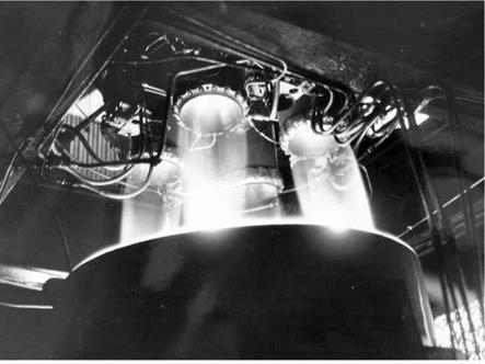
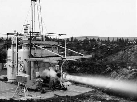
Figure 1. Rolls Royce RZ 2 rocket motors in a test stand at Spadeadam.

Cooling

Rocket chambers will, not surprisingly, get very hot, and ways have to be found to stop them getting too hot. One method is to use film cooling. At the top of the chamber is an injector, where the fuel and oxidant enter the chamber, and it usually resembles a shower head. It is designed so that the fuel and oxidant can mix and burn as quickly as possible. In film cooling, the injector feeds in only fuel at the very edge of the chamber, so that the sides of the chamber wall will be in contact with relatively cool unburnt gas. This usually means a slightly reduced efficiency, as the motor is running fuel rich. The next and most obvious method is to use the incoming fuel to cool the chamber walls before being injected into the chamber. This is called regenerative cooling. One way to do this is to have a double walled chamber, with the fuel flowing between the two walls. This tends to be rather heavy – the pressure in the chamber is obviously quite high, and so the walls need to be robust. This is illustrated in the de Havilland Spectre motor shown in Figure 6.

A refinement on this method was to make a chamber of thin nickel tubes brazed together. Reinforcing bands were usually attached around the tubes, but overall, the construction was much lighter. This technique was first used in the RZ 2 motor for Blue Streak and the chambers of the Stentor motor for the Blue Steel missile. Fuel or oxidant then flows through the tubes to cool the chamber.

Sometimes the expansion cone for upper stages is left as plain metal, and this is sometimes referred to as ‘radiation cooling’ – in other words, the metal is left to glow red hot and literally radiates its heat away into the vacuum of space.

Cooling

Figure 5. A double walled chamber. In this de Havilland Spectre motor, HTP is used as the coolant.

Cooling

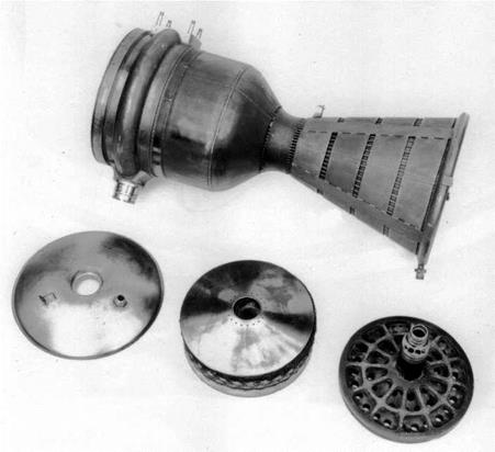
Figure 6. A sectioned example of a liquid hydrogen chamber made at RPE. It has been fabricated from a series of nickel tubes pressed into shape and brazed together. Fuel would flow through the tubes as a coolant.

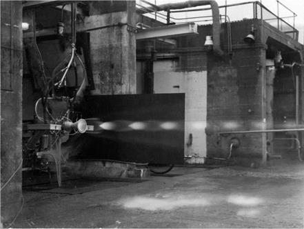
Lubbock and his co-workers at the Fuel Oil Technical Laboratory in Fulham, London, were the first in the UK to work on liquid fuelled rocket motors. Their first design, called Lizzie, was fuelled by LOX (liquid oxygen) and petrol. It was a very simple device: the propellants were forced into the combustion chamber using high pressure nitrogen, so no pumps and other ancillary equipment were needed. It was intended for rocket assisted take-off in aircraft such as the Wellington. In 1946 it was the first liquid fuelled rocket motor to be test fired at the RPD Westcott, and was eventually developed to give thrusts of up to 2000 lb.

Подпись: Figure 7. ‘Lizzie in a test shed at Westcott. Lizzie was used to power the Liquid Oxygen Petrol/

Guided Aerial Projectile, or LOP/GAP, which was an

early test vehicle, fired from

Aberporth in Wales, and later, the Rocket Test Vehicle 1 or RTV-1. Problems cooling the engine led to a change of fuel to a methanol/water mixture. As a consequence of work with Lizzie, it was realised that hydrocarbons did not act as good coolants for rocket engines, and that their flame temperatures are also relatively high, exacerbating the cooling problem. Kerosene was not considered again for rocket motors in Britain for some years.

LIQUID OXYGEN MANUFACTURING PLANT

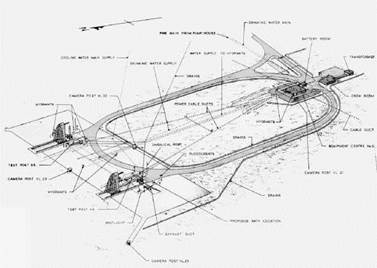
To provide for the large consumption of liquid oxygen, a manufacturing plant has been constructed at Spadeadam. The plant is capable of producing a total of approx. 100-tons of liquid oxygen per 24-day in addition to liquid and gaseous nitrogen. The liquid oxygen is transported by road tankers from the plant to the storage tanks in the test areas, the nitrogen gas is pumped by pipeline to high pressure reservoirs in each of the areas.21

LIQUID OXYGEN MANUFACTURING PLANT

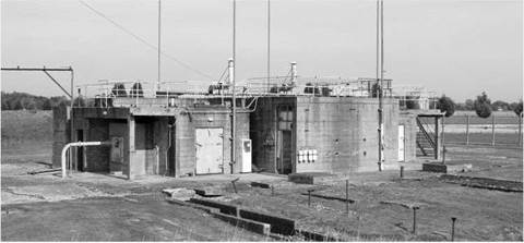
Figure 41. Rocket test stands at Spadeadam.

Spadeadam was built by the Ministry of Works under the supervision of the Ministry of Supply. It was one of the few areas of the whole MRBM programme over which the Treasury had direct control. (It was probably also the most expensive – the estimate of the cost at the time of cancellation was around £24 million). They kept spending under a tight rein, an example of this being when PFG Twinn of the Ministry of Supply wrote to the Treasury asking to be able to spend up to £10,000 on particular items without seeking direct Treasury authorisation. Reluctantly, the Treasury agreed.

Spadeadam was obviously extremely remote, which is why it was chosen in the first place. This did lead to transport difficulties, particularly when showing visitors round. Twinn requested authorisation for some transport in the form of:

1 Ford Consul Black with Heater Saloon 4-6 seats £556

1 Ford Prefect ditto ditto 4 seats £42422

To which the Treasury replied:

We approve the purchase of the Ford Consul, but would be grateful if you would substitute a Ford Popular for the proposed Ford Prefect. Hundreds of Populars are in use in Government service, and we would rather keep to this cheaper 4-seater model.

It really is quite extraordinary that the ministries should be debating the relative merits of a Ford Prefect or a Ford Popular. One cannot quite see the same problem arising at Cape Canaveral.

In July 1959, an official from the Treasury, Mr JA Marshall, set off to inspect Spadeadam in the company of Mr William Downey from the Ministry of Supply. ‘The visit was enjoyable (in spite of almost continual rain) and instructive,’23 he remarked.

In general, he approved: ‘The administrative block is a modest and simple construction as far as I saw it, and there certainly appears to be nothing lavish here.’

But later he was to observe one example of:

… what I would regard as some extravagance.

This is in the housing of the lines which run from the control and recording centre to each of the four stands. It has been put wholly underground. in a tunnel some 400 yards along.

Other cables had been put in an over ground duct. Mr Marshall enquired why this had not been done here. He was told: ‘. had it not been so placed, it would have obscured the view of those in the control centre’.

It also had to be carried under a road, but Mr Armstrong was not entirely convinced it had been necessary to put the entire length of cable underground.

Despite this particular example of ‘extravagance’, Mr Marshall seemed satisfied with his visit. He was ‘well impressed by all I saw’, which included the control rooms, full of:

electronic instrumentation provided to record every possible facet of the test for subsequent analysis. To the layman this produces a hopelessly bewildering mass of knobs, buttons, recording graphs, lights etc’

He goes on:

Mr. Downey had the courage to ask the schoolboy question: “Which is the button which actually sets it going?”. The scientist who was showing us round was utterly at a loss for about a quarter of a minute!

There were other problems. ‘Commander Williams, the senior Rolls Royce representative, who is the general manager of the place, had a go at me on two minor things’.

This related to the housing which had been built for those working at Spadeadam.

He said he thought the Treasury were unduly mean in not allowing them to build a higher proportion of garages… a number of people who have no garages… do have cars and keep them standing in the street… Since the streets are fairly narrow – the whole estate is on very modest lines – this could be a serious nuisance…

And also:

He also thought we underestimated the difficulties they faced when we insisted on a certain proportion of the houses having two bedrooms instead of allowing them to be all three, or in a small number of cases, four-bedroomed.

How much was the Treasury saving? Mr Marshall noted that ‘… the additional capital cost of the three bedroomed house is only £70 …’, but on the other hand, ‘we get an extra 5s. a week rent back from it’.

5s. means 5 shillings, or 25p in decimal money. The extra room would have paid for itself in just over five years.

If Blue Streak had gone ahead in its military guise, then a considerable number (no figure has been found, but a reasonable estimate might be between 10 and 20) of experimental and proving vehicles would be needed, as well as the 60 or so production missiles, starting in 1960 and ending by about 1966. Somewhat optimistically, the development schedule had called for the first missile to be fired from Woomera around mid-1960. As it was, the first vehicle was not fired until 1964, and there were a total of 11 firings by 1971 (in practice, more were built and tested, as there were some basic, non-flight, development vehicles, and also some which were used to check at the sites at Woomera and Kourou).

Thus after the cancellation, the tempo of work slowed considerably, and only one of the missile test stands, C3, was completed. There were also inevitable redundancies and a considerable drop in morale. In May 1967, Val Cleaver, Chief Engineer of the Rocket Department at Rolls Royce, wrote of the need ‘to raise morale and inspire some confidence in the future of the establishment’24, but apart from the test site for the liquid hydrogen RZ 20 motor, no further development work was carried out at Spadeadam.

LIQUID OXYGEN MANUFACTURING PLANT

Figure 42. RZ 1 chamber on P site at RPE Westcott.

Spadeadam would take time to build, so whilst it was being constructed, Rolls Royce used the P stand at Westcott for preliminary testing of the Rocketdyne derived RZ 1. Most of the runs were of very short duration – usually just a few seconds. Progress was delayed by a spillage of liquid oxygen onto the steel girders, which caused them to crack. One of the longest test runs was also the last, on an open day at which the Press was present. A motor was fired for 20 seconds, and on being checked after the firing, it was found that the gear box between the turbines and the pumps had disintegrated. A fraction of a second more, and the firing might have become very spectacular.

So from mid-1957, testing and development proceeded apace. At Hatfield in

Hertfordshire, large structures were built to house the testing of early, non-flight vehicles. These were for checking the strength of the vehicle structure and for such tasks as determining whether half a ton of fuel could be pumped from the tanks each second. Engine testing was carried out separately by Rolls Royce, first at a test site at Westcott and then at the purpose-built facility at Spadeadam in Cumbria. Here, in addition to engine development, assembled vehicles could be static fired. Once tested, they would then be taken apart for transport to Woomera.

Transport proved to be a difficulty. The large size of the tanks meant that very few aircraft would be suitable, and those which were, such as the Bristol Freighter, had limited range. This meant a great many countries would be overflown on the route from the UK to the Antipodes, and, given the nature of the cargo, political difficulties were foreseen. The problem was solved when the RAAF bought Fockheed Hercules aircraft: one of these could be leased from Australia for the purpose. And given the extra range of the Hercules, the overflying problem could be reduced by going westward round the world, over Canada and the US. As it would turn out, the tank of the first missile was at Fos Angeles when the cancellation was announced, and it was returned to the UK. All subsequent civil vehicles were transported by road and sea.

Another of the major problems in the early development was that of guidance. The contract had been given to Sperry, but they were struggling: ‘… accuracies being demanded from the inertial equipment for this project are extremely high and very marginal. It does seem that these accuracies are just

Figure 43. Cutaway view about obtainable,..’25 in January 1956. There is a of Blue Streak. despairing cry from the Director of Air Navigation in

October 1956: ‘There does not yet exist, I believe, anywhere in the world a gyroscope suitable for Blue Streak.’26 This was not quite true: American gyroscopes were very much more advanced, and Ferranti was eventually given the job of adapting Kearfott gyroscopes for the guidance system. Although these were probably not the best the Americans had under development, they were perhaps the best they were prepared to make available to the UK. And in November 1956: ‘It will thus be seen that, though the Blue Steel situation is parlous, the Blue Streak position is even more desperate’. A working design was finally produced, although in the end it was never used: the guidance system was cancelled at the same time as the missile. A satellite launcher needed a much less complicated system, and scrapping the Blue Streak inertial guidance could save money.

As the 1960s progressed, inertial navigation was to become much improved: a system designed for the TSR 2 aircraft was adapted for Black Arrow. Blue Steel was left to soldier on with a much earlier design, which, with its valves, was very power hungry. Again, the penalty was being paid for being early in the field.

Подпись: Figure 44. An early test vehicle being lifted up into the stand at the de Havilland factory at Hatfield. But the next, and most controversial, point about Blue Streak was to be its proposed means of deployment. To have the missile sited on the ground in the open, as the Thor missiles were, was pointless. A pre­emptive strike by relatively few Russian missiles would have destroyed every site before a missile could be fired in retaliation. As all sides in the Cold War realised, land-based missiles would have to be sited in ‘invulnerable’ silos, although the word ‘silo’ was not in usage in the UK at that time. Indeed, the two phrases used became code phrases, showing which side of the controversy you were on. ‘Underground launcher’ was the phrase used by those in

Подпись: 11 12 TNA: PRO T 225/1775. Guided weapons development contracts: Blue Streak and Black Knight. 13 Ibid. 14 Ibid. 15 TNA: PRO T 225/1150. ‘Blue Streak’ medium range ballistic missile: Spadeadam test site. Memo by DR Serpell, 18 October 1956. 16 TNA: PRO T 225/1775. Guided weapons development contracts: Blue Streak and Black Knight. 17 TNA: PRO AVIA 65/714. Spadeadam engine testing: Rolls Royce Ltd. 18 TNA: PRO AIR 20/10299. Ballistic missiles: minutes of Joint US/UK Medium Range Ballistic Missile Advisory Committee and related papers. 19 TNA: PRO T 225/1150. ‘Blue Streak’ medium range ballistic missile: Spadeadam test site. Memo by DR Serpell, 30 October 1956. 20 Ibid. Memo by DR Serpell, 3 November 1956. 21 TNA: PRO AVIA 65/715. Spadeadam engine testing: Rolls Royce Ltd. 22 TNA: PRO T 225/1150. ‘Blue Streak’ medium range ballistic missile: Spadeadam test site. PGF Twinn to JA Marshall 17 March 1958. favour of the project, ‘fixed sites’ if you were against. ‘Fixed sites’ were perceived as being vulnerable. Airfields, somehow, were not perceived as being vulnerable – although they were as ‘fixed’ as any missile launcher. [4]

23 TNA: PRO T 225/1424. ‘Blue Streak’ medium range ballistic missile: test site, Spadeadam. JA Marshall 10 July 1959.

24 TNA: PRO AVIA 92/232. Spadeadam: liquid hydrogen-liquid oxygen thrust chamber test facility. Cleaver to CGWL.

25 TNA: PRO AVIA 54/2135. Blue Streak development: inertia guidance.

26 Ibid.

Black Knight

What was Black Knight, and why was it necessary?

One of the many unknowns when work began on Blue Streak was what would happen when the vehicle carrying the warhead re-entered the atmosphere. To cover a range of 2,000 miles or more, the vehicle would have to be travelling at very high speed – around four kilometres a second. The time of flight would be of the order of 20 minutes, most of it spent in the vacuum of space. Various problems arise when the vehicle re-enters the atmosphere. Firstly, will it be aerodynamically stable? Secondly, will it be able to withstand the forces imposed by the deceleration? Thirdly, will it simply burn up, as a meteorite does?

The point at which all the aerodynamic forces of the vehicle act is called the ‘centre of pressure’. It is important that the centre of pressure is well behind the centre of gravity, otherwise the vehicle might ‘flip over’. Whichever shape is chosen, it must be stable, else its flight path cannot be predicted with any accuracy.

A sphere can be ruled out immediately: it is aerodynamically unstable and will tumble as it falls (Eiffel demonstrated this by dropping cannonballs off his tower). An alternative shape is a cone with a rounded base, and this can be oriented so it enters the atmosphere ‘blunt end first’ or ‘sharp end first’. The ‘blunt end first’ configuration is familiar from the Mercury, Gemini and Apollo capsules. The ‘blunt end first’ also has a much higher drag, or air resistance.

The ‘sharp end first’, having a lower drag, is not slowed down so much in the thinner upper layers of the atmosphere. Instead, it is still moving fast when it meets the denser air lower down. The result is that the deceleration is then more abrupt, the forces greater and the peak heating greater. The advantage from a military point of view is that it would be much more difficult to stop, and it would also be rather more accurate.

The heating effect was another unknown. Effectively, the kinetic energy of the vehicle is almost all converted to heat in a very short period of time. This does not happen by ‘friction’, as is commonly stated, but by a different mechanism. The air in front of the vehicle is being compressed, and when gases are compressed they heat up. To compress them, work has to be done; this work appears as heat. If the heat is given no chance to escape, then the heating is described as ‘adiabatic’. Heat is then transferred from the hot gases to the vehicle.

RAE decided to go for the ‘sharp end first’ design, and carried out calculations on the effects of re-entry.1 Calculations are one thing; what happens in reality is another. There was only one way to find out: fire a model re-entry head vertically upwards, and see what happens when it comes back down again. To achieve a speed of 4 km/s on re-entry meant sending the body 800 km high. In addition, RAE wanted to carry instruments in the head to measure temperatures and accelerations, so it had to be a reasonable size. A re-entry head weight of 200 lb was chosen.

Black Knight

Figure 78. The BK09 re-entry head, representative of the ‘sharp end’ first design.

An example of the shape chosen is shown above – this is a drawing of the re­entry head flown on BK09.2

The next question was what sort of vehicle could launch the model re-entry vehicle? Could a solid fuelled vehicle do the job? The advantage of using solid fuel motors is that they can be clustered together ‘off the shelf’. A further advantage is that of staging: it is quite easy to arrange a stack of solid fuel motors into a three or four stage vehicle.

One crude method of estimating the effectiveness of a rocket motor is to estimate its total impulse – that is, thrust x burn time. Black Knight as originally designed gave a total impulse of around 2,300,000 lbf. seconds, whereas one of the larger solid fuel motors of the time, the Raven VI, gave a total impulse of
around 450,000 lbf. seconds. Hence five Ravens would give the same impulse. Using solid fuel motors also made staging easier, producing a more efficient vehicle. The sketches on the left show some possible two stage vehicles.3

Подпись: Figure 79. Sketches for a solid fuelled test vehicle. These were only speculative and were not fully worked. On the other hand, another way of estimating the performance of rocket vehicles, as mentioned earlier, is the mass fraction or mass ratio, which is defined as (initial mass)/(final mass). Here Black Knight would have won hands down: any British solid fuelled vehicle of the time would have had a very poor mass ratio, whereas that of Black Knight was extremely good.

The RAE estimated that the mass ratio for a solid fuel motor of around one million lbf. seconds impulse would be in the region of five. For Black Knight, the ratio turns out to be 18. In performance terms, this means that, all other factors being equal, Black Knight would have a final velocity nearly double that of a solid fuel motor design (to be precise, 1.8 times greater). In addition, a large solid fuel vehicle would not have been so easy to steer, whereas Black Knight was steered by swivelling the liquid fuel chambers.

But there was also another reason, never quite spelled out, which was that Britain had never built a ballistic rocket before, let alone one on the scale of Blue Streak. Black Knight would be a chance to gain experience not only in the building of such rockets, but also other matters such as launch technique, and so on. Indeed, de Havilland was given the responsibility for the launches at Woomera, in anticipation of Blue Streak, and somewhat to the chagrin of Saunders Roe.

Since the specification4 was for a quick and inexpensive solution, then it was obvious HTP motors would be chosen, and since RAE was running the programme, then it was also fairly obvious that RPE’s motor, the Gamma, would be chosen. The Gamma had a thrust of around 4,100 lb; four of them clustered together gave a thrust of 16,400 lb. This set the weight of the vehicle: a lift off

Подпись: €> Figure 80. The Gamma 201, designed and built by Armstrong Siddeley using the Gamma chamber developed by the RPE. acceleration of 0.3 g meant an all-up weight of (16,400/1.3) lb or around 12,600 lb.

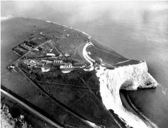
Armstrong Siddeley (as they then were) at Anstey were given the contract to build and test the new motor, which would be called the Gamma 201. When the motor for a particular vehicle was completed, it would be taken down from Anstey to Cowes, to be mated to the tank section. Saunders Roe then needed a site to carry out static testing – where the vehicle is filled with fuel and the motors fired, but without releasing it. The Needles battery at the end of the Isle of Wight was War Office property, but was now surplus to requirements. Saunders Roe proposed building the site close to the battery, just round to the south, in a natural amphitheatre formed in the chalk.5 The area was known as High Down, and Figure 81 below shows the site soon after completion. The two gantries were where the vehicles were held down for static testing. The site has not yet been landscaped, as can be seen from the areas of raw chalk.

Some of the site is still in existence, principally the curving concrete walkway in the amphitheatre. Figure 81 (bottom) shows the site as it was in 2010, more than 50 years after it was constructed.

In the centre was the control room: test firings were carried out from here and the various instrumentation read outs were recorded. In the 1950s, the main method of recording data was by using a pen recorder with a long strip of paper. All the instrumentation would have been analogue. At each end of the walkway
was a gantry, the bases of which remain today. The vehicle would have been mounted inside the gantry, and below was a large iron blast deflector, which could be water-cooled during engine tests. The gantries and control rooms were designed to be as identical to their Australian counterparts as possible so as to reduce the chance of problems on countdown or launch. There would also have been tanks behind the main site for the kerosene and HTP, as well as workshops and other facilities. According to the architect, the part of the site that gave him greatest difficulty was the water reservoir for cooling the blast deflectors: the water had to be pumped up from nearby Yarmouth through a very inadequate water main.6

Подпись: Figure 81. Top: the High Down test site under construction in 1957, and below, the site as it is today, now owned by the National Trust. In these days of Green Belt, planning permission, NIMBYism, and so on, it seems incredible that a rocket test site could be built on one of the most scenic sites in Britain without objection, but it was also obvious from the files that the idea of anyone objecting did not occur to the official mind. The site belonged to the War Office, was now surplus to requirements, and a test site was needed. Planning permission as we now know it was not necessary in those days.

It is indeed a scenic spot, now owned by the National Trust. Cars are not allowed along the cliff road up from Yarmouth, but there is a bus which runs up to the Needles Battery for those who do not care for the walk. The site overlooks the Needles rocks and lighthouse. Beyond the lighthouse is the Shingle Bank, and even on the calmest days, broken water can be seen here. In the far distance are the chalk cliffs of Studland Bay and Swanage, with the Purbeck Hills in the background. Equally, it must have been a bleak place in a southwesterly gale in winter.

The Saunders Roe brochure for the proposed test site stated: ‘The cost of renovating existing buildings, cutting the road and installing the complete test facility is estimated to be no more than £45,000.’7 This turned out to be somewhat optimistic, but to build a static test stand for that figure is good value for money.

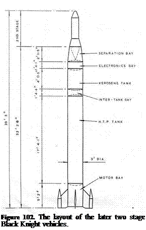
Black KnightBlack Knight was a slim cylinder, 3 ft in diameter. Its exact height would vary depending on the payload, but it was 32 ft 3 inches to the top of the separation bay. Initially it was a single stage vehicle; later versions used a solid fuel Cuckoo motor as a second stage. Some also used some small Imp motors to push the re-entry head away from the main body, but to describe this as a three stage version, as some RAE reports did, is being a little optimistic.

Starting at the bottom, there was the propulsion bay, 36 inches diameter and 56 inches high, which held the four

Figure 82. An early Black Knight at rocket chambers, the turbine to drive the Woomera. This is an early ‘proving pumps, hydraulics and other equipment, round’, whh a non-separating head and was built by Armstrong Siddeley at

Anstey, before being taken down to Cowes to be attached to the tank section. It was easy to dismount for transport, and could be tested and calibrated before being assembled into the vehicle.

The thrust chambers were ‘toed in’ slightly so that the thrust line passed through the centre of gravity. Four fins were fastened to the engine bay; these were for aerodynamic stability during flight. Attached to two of the fins were pods. One held a radar transponder (a transponder receives the radar signals and rebroadcasts them to give a stronger signal), the other a telemetry transmitter to return data, and an electronic flashgun. This was set to flash every four seconds, and since the launch was at night, the vehicle’s progress could be followed

о

optically.

Above the engine bay was the HTP tank, 208 inches long along the cylindrical section. Two tubes of manganese dioxide were attached to the tank, and if the destruct signal was sent, explosive would drive the black powder into the tank. Manganese dioxide is a catalyst for the decomposition of hydrogen peroxide, and the resultant steam and oxygen gas would blow the tank apart.

Black KnightThe bay between the HTP and kerosene tanks contained air bottles which were used to pressurise the HTP tank. The kerosene tank was not directly pressurised, as the hydrostatic head was sufficient to prime the pumps. One striking feature is the size of the HTP tank compared with the kerosene tank: 208 inches compared with 48 inches. The mass of HTP was over eight times that of kerosene, although the greater density meant the volume ratio was smaller.

Above the kerosene tank was the pressurised electronics bay. This housed instrumentation, telemetry, control system electrics, autopilot gyroscopes, a command receiver and electrical power supplies well Figure 83. Etectronic fbsh gun away from the worst effects of engine induced installed in one of the pods attached vibration and heating. Above this would be

to the fins. the payload, which would differ from flight to

flight. The tubes running down the side of the vehicle were fibreglass fairings covering the kerosene feed pipe and the various electrical cables.

Initial ideas for the tank structure was to make it from very thin aluminium (26 Standard Wire Gauge (SWG), which is 0.018 inches or 0.46 mm) supported by 16 stringers.9 This may well have been by analogy with Blue Streak, although the stringers in the case for Blue Streak were there for a different reason. The RAE was uneasy about the structure, mainly because the stringers would experience aerodynamic heating on ascent, which would lead to a variety of problems with them, the main being expansion. If the stringers expanded and the tank did not, then unpredictable stresses would be set up. At least one such tank was constructed; photographs of the setting up of the gantries at High Down and
at Woomera show a white painted stringered missile body being used to check the facilities.

The change to 20 SWG (0.036 inches or 0.914 mm) tank thickness did incur a slight weight penalty, which was estimated at 50 lb. The initial weight breakdown for the vehicle was given as 1,100 lb vehicle weight plus 200 lb for the head, or 1,300 lb. 11,250 lb fuel gave a total weight of 12,550 lb. As is always the case, weights crept up during the detailed design process; the first vehicle, BK01, came in at 1,480 lb.10

Black Knight

Figure 84. An early non flight vehicle being used to test out the gantry at Woomera. This was a thin walled stringered version which was not put into production.

Close inspection shows a series of holes cut in the side of the motor bay. These were designed to reduce what is called ‘base drag’. When the vehicle is climbing up through the atmosphere, it encounters air resistance. If the rocket has a blunt end, the air will swirl around behind it, producing extra drag. The purpose of these ‘bleed holes’ was to let air flow in, reducing this base drag.

To test the idea, a small solid fuelled vehicle was prepared, which had four small rocket motors and a take-off weight of 140 lb, the rear section being a scaled version of the Black Knight propulsion bay. Several of these were test fired in Wales, with the conclusion that the bleed holes gave an estimated improvement in the final velocity of up to 200 ft per second. Further tests were needed to check on what is called ‘recirculation’ where hot exhaust gases get swept back into the engine bay.11

Black Knight

Figure 85. Base drag test vehicle in flight.

One effect which was not appreciated at the time was the expansion of the exhaust plumes in the near vacuum of high altitude. This did cause problems in some of the early launches, when the kerosene supply to the motors was cut, leading to a period of what was called ‘cold thrusting’ – that is, the motors were running on HTP only. This works, but is much less effective. The problem was investigated by firing a Gamma motor in a vacuum chamber at Westcott. The solution was to fit spring loaded flaps over the holes, so that they would open in the atmosphere, but as the air got thinner, the springs would force the flaps shut.

To improve performance further, a small solid fuel motor was added as a second stage. This was the Cuckoo – originally intended as a launch boost for the Skylark (the name apparently derived from the idea that the Cuckoo kicked the Skylark from out of its nest!). The original version was the Cuckoo IA, first flown in April 1960; the Cuckoo IB was identical apart from a changed interface from Skylark to Black Knight. It was replaced by the Cuckoo II, which had an improved performance. The Cuckoo would later go on to be developed further in extended versions of Skylark. The oddest feature is that the second stage is mounted pointing downwards. At the very top, under the jettisonable fairing, is a gas bottle with jets. This was used to spin up the Cuckoo motor after separation
from the main stage, which then coasted up to apogee then fell back to earth. An ionisation gauge was used to detect the start of the atmosphere, at which point the motor was fired. After motor cut off, the head was pushed away from the empty casing so that they would re­enter separately.

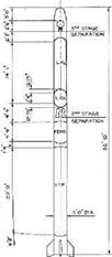
Подпись: Figure 86. BK16 layout. An even more elaborate system was used in later flights.

This involved a cradle which was referred to as a ‘sabot’

(French for ‘clog’, but in this context it has the artillery meaning of a device used in a firearm or cannon to fire a projectile which must be held in a precise position). The re-entry head was held in the sabot, which was attached to the Cuckoo motor by a long nylon rope. The aim was to propel the head well clear of the spent motor case.

The sabot system was necessary to keep the second stage re-entry out of the field of view of the instruments tracking the re-entry head. Separation took place at high altitude so as to give the head sufficient time to be at least 20,000 ft ahead of the second stage at 300,000 ft altitude. It was built on a magnesium alloy plate, on which there was an aluminium seat shaped to the re-entry head. It gave the head a velocity increment of the order of 400 ft/second using four Imp X motors. The thrust of the Imps blew off four panels on the separation bay, and in the case of BK20 it is possible that there was some interference at separation. Despite exhaustive ground testing on the range at Larkhill (Salisbury Plain) it was not possible to simulate the effects of vacuum and low temperature on the nylon.12

The lanyard as originally conceived consisted of 8 ft of steel wire followed by 120 ft of undrawn nylon. It was changed to 310 ft of slightly thinner nylon. The steel wire and first 20 ft of the nylon were covered with a woven asbestos sheath to protect it against the flame of the Imp motors, which had a burn time of a third of a second.

The final arrangement was sometimes and somewhat optimistically referred to as a three stage version: the Black Knight first stage, the Cuckoo second stage, and the Imp motors making the third stage. Starting at the top, below the nose cap is a gas bottle, which with attached jets, was used to spin the stage up. Below that is the Cuckoo motor, pointing Figure 87. The lanyard and sabot arrangement. downwards, then the sabot and lanyard arrangement, with the re-entry head itself at the very bottom.13

Black KnightAs we shall see in the next chapter, the lanyard system was not always a success for a variety of reasons.

Подпись: Figure 88. The upper stages for the later Dazzle flights. The head was pushed away from the Cuckoo second stage with small Imp motors, using a lanyard/sabot arrangement.

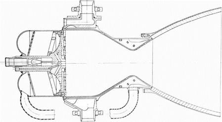
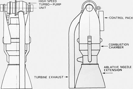
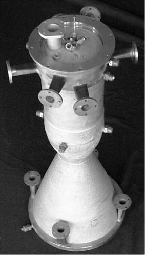
Changes to Black Knight were made incrementally throughout its life. The other major improvement was to replace the original rocket chambers with ones derived from the Stentor motor – the Stentor being developed by Armstrong Siddeley for the Blue Steel missile. The new chamber was lighter, but equally importantly, it was much easier to control the mixture ratio of HTP to kerosene in the new motor, making it more efficient. The maximum thrust was also greater – potentially 25,000 lb, but in practice an intermediate thrust level of 21,600 lb was used. The new motor was named the Gamma 301. A further refinement was proposed for the 54-inch Black Knight, the Gamma 304, which would have had only one turbine and pump feeding each chamber, rather than the four separate ones in the Gamma 301.

Black Knight

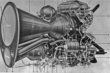
Figure 89. Gamma 301 motor using the small chamber from the Stentor motor.

5 TNA: PRO AVIA 48/57. Black Knight: re-entry test vehicle. Saunders Roe Technical Publication 144.

6 Personal communication.

7 TNA: PRO AVIA 48/57. Black Knight: re-entry test vehicle.

8 TNA: PRO AVIA 6/21517. Black Knight electronic flash installation for optical tracking.

9 TNA: PRO AVIA 13/1269. ‘Black Knight’: body tests.

10 Ibid.

11 TNA: PRO AVIA 6/19890. Ballistic test vehicle Black Knight. (Technical Note Number G. W. 503, HGR Robinson.)

12 TNA: PRO AVIA 6/21754. Black Knight vehicles of project DAZZLE and their flight behaviour. RAE Technical Report 68076.

13 TNA: PRO DSIR 23/36396. The Black Knight vehicles of project DAZZLE and their flight behaviour.

BK19

Two stage. Launched 6 August 1964 at 02:45. Apogee 374 miles.

This was the first launch with the Gamma 301 motor rated at the full thrust of 21,600 lb, and all vehicle systems were successful. The re-entry head for this flight was a copper sphere, which was recovered the next morning. Although it had split into two and had been scored and dented by the impact with the ground, it was in surprisingly good condition.

Could Britain Have Launched an Astronaut into Orbit?

The science fiction author Stephen Baxter has written a short story, ‘Prospero One’, about the first and last launch of two British astronauts from Woomera. His ‘Black Prince III’ launch vehicle uses five Blue Streak boosters strapped together (this does seem a little over the top). But what would be needed for a manned capsule? Could it be done with British technology as of, for example, 1964 (and without five Blue Streaks)? The answer is yes – but only just.

America’s first manned spacecraft was the Mercury capsule, which weighed 4,300 lb at launch and 3,000 lb once in orbit (the escape tower was jettisoned during ascent). Mercury was the smallest capsule into which a man could be squeezed; there was no room or weight spare for anything else, and it had very limited endurance. The more capable two man capsule, Gemini, weighed in at 8,500 lb in orbit. Gemini could stay in orbit for several days, and carry a reasonable amount of equipment.

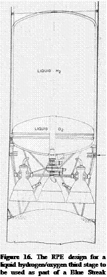
Given the original Black Prince design had a payload of around 2,200 lb into low earth orbit, it would have to be uprated very considerably, but by this time RPE had developed liquid hydrogen motors of around 4,000 lb thrust, so making a motor of 8,000 lb thrust would not be that difficult. The American Centaur stage had a thrust of 30,000 lb; four of the RPE motors gives a thrust of 32,000 lb. Centaur was even built in stainless steel using the same balloon technique as Atlas and Blue Streak; de Havilland could no doubt have built a similar stage without much difficulty. Such a vehicle might be able to put a payload in the region of 4,000 lb into orbit, which is close, but not really good enough.

There is the possibility of strap-on boosters: four Black Knight boosters, stripped of all other equipment, might well serve here. They could be uprated to

25,0 lb thrust, giving an extra 100,000 lb thrust at lift-off. This would mean that there would be weight to spare, so that the liquid hydrogen stage could be considerably stretched. Now we might have a vehicle capable of putting 6,000lb or more into orbit – perhaps sufficient, but only just, and by stretching the design as far as it can go.

All this is achievable with the technology of 1964, although developing the liquid hydrogen stage would involve some years work. As to cost: Gemini cost around $1.25 billion, or roughly £500 million at the contemporary exchange rate. The question arises as to whether it would have been worthwhile putting a British astronaut into orbit… and, regrettably, the answer is no. Gemini was merely a stepping stone to Apollo. Now we have an International Space Station but the financial or scientific return from the ISS is negligible, whereas its costs are horrendous.

Units

The past being another country, they did things differently. I have kept almost entirely to the units of the day. Thus feet and inches. 1 metre is 39 inches. Weight was used where today we would (I hope) use mass. Mass is difficult to define, but can be thought of as the inertia of a body. Weight is the force of gravity on that mass. 1 pound, abbreviated lb (derived from Latin libra), is 0.45 kg.

More annoyingly, force was also expressed in lb, meaning in this context the weight of an object with a mass of 1 lb. Modern usage takes the unit of mass as 1 kg and of force as 1 N. The force of gravity on 1 kg is 9.8 N on Earth at sea level. Thus rocket thrust was defined in pound force, sometimes abbreviated to lbf, or plain lb, which would now be written as 0.45 kg x 9.8 N = 4.4 N. A metric tonne is 1000 kg, an imperial ton is 2,240 lb. By a lucky coincidence they are almost identical.

Pressure was usually given in pounds per square inch, psi, or atmospheres. ‘Atmosphere’ is still sometimes used today under the name ‘bar’ (and by extension, the millibar or mb found on weather charts). The modern SI unit of pressure is the newton per square metre (N/m2) or pascal (Pa). 1 atmosphere or 1 bar is approximately 15 psi or 100,000 Pa (100 kPa).

Orbit heights are usually given in nautical miles above the Earth’s surface. A nautical mile is, strictly speaking, one second of arc of a Great Circle on the Earth, or around 2000 yards. A statute mile is 1,760 yards. Thus a nautical mile is a little less than 2 kilometres.

After all this, the merits of the metric system appear obvious!

Acronyms and Abbreviations

AWE – Atomic Weapons Establishment, situated in Aldermaston, Berkshire, and responsible for the development of British nuclear weapons. Now the AWRE or Atomic Weapons Research Establishment.

BND(SG) – British Nuclear Deterrent (Study Group). An ad hoc group set up to report on the deterrent, and which recommended the cancellation of Blue Streak as a military weapon.

BSE – Bristol Siddeley Engines. Armstrong Siddeley merged with Bristol to form Bristol Siddeley Engines, which was later taken over by Rolls Royce.

CGWL – Controller of Guided Weapons and Electronics. A senior post within the Ministry of Supply. The Controller was responsible for overseeing guided weapons projects.

DRPC – Defence Research and Policy Committee. A high level committee which recommended particular lines of research and development.

ELDO – European Launcher and Development Organisation.

GW Department – Guided Weapons Department at the Royal Aircraft Establishment (RAE). Responsible for missile development.

HTP – High Test Peroxide, a mixture of 85% hydrogen peroxide and 15% water.

JIC – Joint Intelligence Committee. Provides advice to the Cabinet related to security, defence and foreign affairs

OR – Operational Requirement. This was the specification for a new weapon. The requirement would be issued by the Air Staff, and the Ministry of Supply was responsible for circulating the requirement to the various aircraft manufacturers, choosing the winning design and overseeing the development of the project.

RAE – Royal Aircraft Establishment, situated in Farnborough, Hampshire, and responsible for Government-directed research into aeronautics.

RPE – Rocket Propulsion Establishment, situated in Westcott, Buckinghamshire, and responsible for research into rocket motors.

S. I. – Specific Impulse. One of the measures of rocket motor performance. The higher the S. I., the better the performance.

Places

Snarler and Screamer

In 1946 the Ministry of Supply asked Armstrong Siddeley Motors to develop a liquid fuel rocket motor with a thrust of 2,000 lb for use as a booster unit for fighters. Initial ideas were for a hydrocarbon/liquid oxygen motor, but after talks with the RAE, the fuel was changed to a mixture of 65% methanol and 35% water. At the time, it was thought that hydrocarbon fuels were not well suited for cooling the chamber. The first test run of the motor, now named Snarler, together with a fuel pump was achieved in February 1949.

Motors designed to be installed in manned aircraft need to be safe and reliable: by May 1950, the motor had achieved 71 minutes of full thrust in testing. A Snarler motor was then installed in the tail of the Hawker P.1040
prototype (forerunner of the Sea Hawk), the new aircraft now being designated the P.1072. Flight trials began in November 1950.

Snarler was capable of being throttled – not always easy to achieve with rocket motors – and had a maximum sea level thrust of 2200 lb. The S. I. of the motor was 195, with a combustion chamber pressure of 300 lb/sq in (2 0bar).

Work on Snarler’s successor, Screamer, began in 1950. Initially intended to give 4,000 lb thrust, the specification given by the Ministry of Supply was changed to a more powerful motor of higher thrust. One of the main differences between Screamer and Snarler is that the Snarler pump was driven externally; Screamer would have its own gas generator to drive the turbines which would power the pumps.

In these early days there was very little design knowledge of gas generators, and it was decided to add water to the combustion mixture to reduce its temperature. Because water was being carried for the gas generator, it was decided to use its excellent cooling properties for the combustion chamber jacket, the heated water then being injected into the combustion chamber itself. Unusually, the combustion chamber had no throat, being a simple cylinder followed by the usual expansion cone.

By 1954, the complete motor was ready for testing, and by September, thrust ratings of 8,000 lb had been achieved. The motor was later installed in the underside of a Meteor for flight testing, but with the cancellation of the Avro 720 rocket interceptor in favour of the Saunders Roe SR53, and the decision to use only HTP in manned vehicles, Screamer was not developed further.