Black Knight
What was Black Knight, and why was it necessary?
One of the many unknowns when work began on Blue Streak was what would happen when the vehicle carrying the warhead re-entered the atmosphere. To cover a range of 2,000 miles or more, the vehicle would have to be travelling at very high speed – around four kilometres a second. The time of flight would be of the order of 20 minutes, most of it spent in the vacuum of space. Various problems arise when the vehicle re-enters the atmosphere. Firstly, will it be aerodynamically stable? Secondly, will it be able to withstand the forces imposed by the deceleration? Thirdly, will it simply burn up, as a meteorite does?
The point at which all the aerodynamic forces of the vehicle act is called the ‘centre of pressure’. It is important that the centre of pressure is well behind the centre of gravity, otherwise the vehicle might ‘flip over’. Whichever shape is chosen, it must be stable, else its flight path cannot be predicted with any accuracy.
A sphere can be ruled out immediately: it is aerodynamically unstable and will tumble as it falls (Eiffel demonstrated this by dropping cannonballs off his tower). An alternative shape is a cone with a rounded base, and this can be oriented so it enters the atmosphere ‘blunt end first’ or ‘sharp end first’. The ‘blunt end first’ configuration is familiar from the Mercury, Gemini and Apollo capsules. The ‘blunt end first’ also has a much higher drag, or air resistance.
The ‘sharp end first’, having a lower drag, is not slowed down so much in the thinner upper layers of the atmosphere. Instead, it is still moving fast when it meets the denser air lower down. The result is that the deceleration is then more abrupt, the forces greater and the peak heating greater. The advantage from a military point of view is that it would be much more difficult to stop, and it would also be rather more accurate.
The heating effect was another unknown. Effectively, the kinetic energy of the vehicle is almost all converted to heat in a very short period of time. This does not happen by ‘friction’, as is commonly stated, but by a different mechanism. The air in front of the vehicle is being compressed, and when gases are compressed they heat up. To compress them, work has to be done; this work appears as heat. If the heat is given no chance to escape, then the heating is described as ‘adiabatic’. Heat is then transferred from the hot gases to the vehicle.
RAE decided to go for the ‘sharp end first’ design, and carried out calculations on the effects of re-entry.1 Calculations are one thing; what happens in reality is another. There was only one way to find out: fire a model re-entry head vertically upwards, and see what happens when it comes back down again. To achieve a speed of 4 km/s on re-entry meant sending the body 800 km high. In addition, RAE wanted to carry instruments in the head to measure temperatures and accelerations, so it had to be a reasonable size. A re-entry head weight of 200 lb was chosen.
|
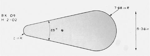
Figure 78. The BK09 re-entry head, representative of the ‘sharp end’ first design. |
An example of the shape chosen is shown above – this is a drawing of the reentry head flown on BK09.2
The next question was what sort of vehicle could launch the model re-entry vehicle? Could a solid fuelled vehicle do the job? The advantage of using solid fuel motors is that they can be clustered together ‘off the shelf’. A further advantage is that of staging: it is quite easy to arrange a stack of solid fuel motors into a three or four stage vehicle.
One crude method of estimating the effectiveness of a rocket motor is to estimate its total impulse – that is, thrust x burn time. Black Knight as originally designed gave a total impulse of around 2,300,000 lbf. seconds, whereas one of the larger solid fuel motors of the time, the Raven VI, gave a total impulse of
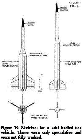
around 450,000 lbf. seconds. Hence five Ravens would give the same impulse. Using solid fuel motors also made staging easier, producing a more efficient vehicle. The sketches on the left show some possible two stage vehicles.3
 On the other hand, another way of estimating the performance of rocket vehicles, as mentioned earlier, is the mass fraction or mass ratio, which is defined as (initial mass)/(final mass). Here Black Knight would have won hands down: any British solid fuelled vehicle of the time would have had a very poor mass ratio, whereas that of Black Knight was extremely good.
The RAE estimated that the mass ratio for a solid fuel motor of around one million lbf. seconds impulse would be in the region of five. For Black Knight, the ratio turns out to be 18. In performance terms, this means that, all other factors being equal, Black Knight would have a final velocity nearly double that of a solid fuel motor design (to be precise, 1.8 times greater). In addition, a large solid fuel vehicle would not have been so easy to steer, whereas Black Knight was steered by swivelling the liquid fuel chambers.
But there was also another reason, never quite spelled out, which was that Britain had never built a ballistic rocket before, let alone one on the scale of Blue Streak. Black Knight would be a chance to gain experience not only in the building of such rockets, but also other matters such as launch technique, and so on. Indeed, de Havilland was given the responsibility for the launches at Woomera, in anticipation of Blue Streak, and somewhat to the chagrin of Saunders Roe.
Since the specification4 was for a quick and inexpensive solution, then it was obvious HTP motors would be chosen, and since RAE was running the programme, then it was also fairly obvious that RPE’s motor, the Gamma, would be chosen. The Gamma had a thrust of around 4,100 lb; four of them clustered together gave a thrust of 16,400 lb. This set the weight of the vehicle: a lift off
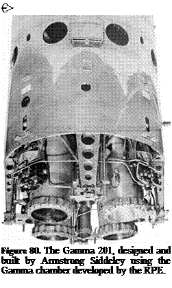 acceleration of 0.3 g meant an all-up weight of (16,400/1.3) lb or around 12,600 lb.
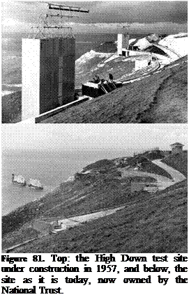
Armstrong Siddeley (as they then were) at Anstey were given the contract to build and test the new motor, which would be called the Gamma 201. When the motor for a particular vehicle was completed, it would be taken down from Anstey to Cowes, to be mated to the tank section. Saunders Roe then needed a site to carry out static testing – where the vehicle is filled with fuel and the motors fired, but without releasing it. The Needles battery at the end of the Isle of Wight was War Office property, but was now surplus to requirements. Saunders Roe proposed building the site close to the battery, just round to the south, in a natural amphitheatre formed in the chalk.5 The area was known as High Down, and Figure 81 below shows the site soon after completion. The two gantries were where the vehicles were held down for static testing. The site has not yet been landscaped, as can be seen from the areas of raw chalk.
Some of the site is still in existence, principally the curving concrete walkway in the amphitheatre. Figure 81 (bottom) shows the site as it was in 2010, more than 50 years after it was constructed.
In the centre was the control room: test firings were carried out from here and the various instrumentation read outs were recorded. In the 1950s, the main method of recording data was by using a pen recorder with a long strip of paper. All the instrumentation would have been analogue. At each end of the walkway
was a gantry, the bases of which remain today. The vehicle would have been mounted inside the gantry, and below was a large iron blast deflector, which could be water-cooled during engine tests. The gantries and control rooms were designed to be as identical to their Australian counterparts as possible so as to reduce the chance of problems on countdown or launch. There would also have been tanks behind the main site for the kerosene and HTP, as well as workshops and other facilities. According to the architect, the part of the site that gave him greatest difficulty was the water reservoir for cooling the blast deflectors: the water had to be pumped up from nearby Yarmouth through a very inadequate water main.6
 In these days of Green Belt, planning permission, NIMBYism, and so on, it seems incredible that a rocket test site could be built on one of the most scenic sites in Britain without objection, but it was also obvious from the files that the idea of anyone objecting did not occur to the official mind. The site belonged to the War Office, was now surplus to requirements, and a test site was needed. Planning permission as we now know it was not necessary in those days.
It is indeed a scenic spot, now owned by the National Trust. Cars are not allowed along the cliff road up from Yarmouth, but there is a bus which runs up to the Needles Battery for those who do not care for the walk. The site overlooks the Needles rocks and lighthouse. Beyond the lighthouse is the Shingle Bank, and even on the calmest days, broken water can be seen here. In the far distance are the chalk cliffs of Studland Bay and Swanage, with the Purbeck Hills in the background. Equally, it must have been a bleak place in a southwesterly gale in winter.
The Saunders Roe brochure for the proposed test site stated: ‘The cost of renovating existing buildings, cutting the road and installing the complete test facility is estimated to be no more than £45,000.’7 This turned out to be somewhat optimistic, but to build a static test stand for that figure is good value for money.
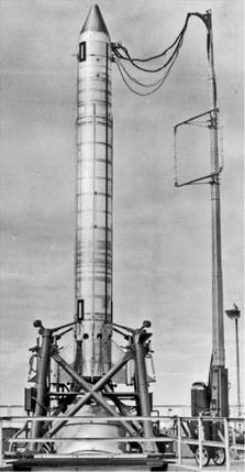 Black Knight was a slim cylinder, 3 ft in diameter. Its exact height would vary depending on the payload, but it was 32 ft 3 inches to the top of the separation bay. Initially it was a single stage vehicle; later versions used a solid fuel Cuckoo motor as a second stage. Some also used some small Imp motors to push the re-entry head away from the main body, but to describe this as a three stage version, as some RAE reports did, is being a little optimistic.
Starting at the bottom, there was the propulsion bay, 36 inches diameter and 56 inches high, which held the four
Figure 82. An early Black Knight at rocket chambers, the turbine to drive the Woomera. This is an early ‘proving pumps, hydraulics and other equipment, round’, whh a non-separating head and was built by Armstrong Siddeley at
Anstey, before being taken down to Cowes to be attached to the tank section. It was easy to dismount for transport, and could be tested and calibrated before being assembled into the vehicle.
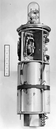
The thrust chambers were ‘toed in’ slightly so that the thrust line passed through the centre of gravity. Four fins were fastened to the engine bay; these were for aerodynamic stability during flight. Attached to two of the fins were pods. One held a radar transponder (a transponder receives the radar signals and rebroadcasts them to give a stronger signal), the other a telemetry transmitter to return data, and an electronic flashgun. This was set to flash every four seconds, and since the launch was at night, the vehicle’s progress could be followed
о
optically.
Above the engine bay was the HTP tank, 208 inches long along the cylindrical section. Two tubes of manganese dioxide were attached to the tank, and if the destruct signal was sent, explosive would drive the black powder into the tank. Manganese dioxide is a catalyst for the decomposition of hydrogen peroxide, and the resultant steam and oxygen gas would blow the tank apart.
 The bay between the HTP and kerosene tanks contained air bottles which were used to pressurise the HTP tank. The kerosene tank was not directly pressurised, as the hydrostatic head was sufficient to prime the pumps. One striking feature is the size of the HTP tank compared with the kerosene tank: 208 inches compared with 48 inches. The mass of HTP was over eight times that of kerosene, although the greater density meant the volume ratio was smaller.
Above the kerosene tank was the pressurised electronics bay. This housed instrumentation, telemetry, control system electrics, autopilot gyroscopes, a command receiver and electrical power supplies well Figure 83. Etectronic fbsh gun away from the worst effects of engine induced installed in one of the pods attached vibration and heating. Above this would be
to the fins. the payload, which would differ from flight to
flight. The tubes running down the side of the vehicle were fibreglass fairings covering the kerosene feed pipe and the various electrical cables.
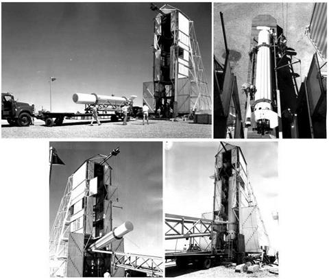
Initial ideas for the tank structure was to make it from very thin aluminium (26 Standard Wire Gauge (SWG), which is 0.018 inches or 0.46 mm) supported by 16 stringers.9 This may well have been by analogy with Blue Streak, although the stringers in the case for Blue Streak were there for a different reason. The RAE was uneasy about the structure, mainly because the stringers would experience aerodynamic heating on ascent, which would lead to a variety of problems with them, the main being expansion. If the stringers expanded and the tank did not, then unpredictable stresses would be set up. At least one such tank was constructed; photographs of the setting up of the gantries at High Down and
at Woomera show a white painted stringered missile body being used to check the facilities.
The change to 20 SWG (0.036 inches or 0.914 mm) tank thickness did incur a slight weight penalty, which was estimated at 50 lb. The initial weight breakdown for the vehicle was given as 1,100 lb vehicle weight plus 200 lb for the head, or 1,300 lb. 11,250 lb fuel gave a total weight of 12,550 lb. As is always the case, weights crept up during the detailed design process; the first vehicle, BK01, came in at 1,480 lb.10
|
Figure 84. An early non flight vehicle being used to test out the gantry at Woomera. This was a thin walled stringered version which was not put into production. |
Close inspection shows a series of holes cut in the side of the motor bay. These were designed to reduce what is called ‘base drag’. When the vehicle is climbing up through the atmosphere, it encounters air resistance. If the rocket has a blunt end, the air will swirl around behind it, producing extra drag. The purpose of these ‘bleed holes’ was to let air flow in, reducing this base drag.
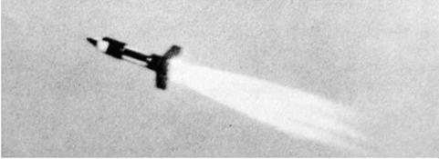
To test the idea, a small solid fuelled vehicle was prepared, which had four small rocket motors and a take-off weight of 140 lb, the rear section being a scaled version of the Black Knight propulsion bay. Several of these were test fired in Wales, with the conclusion that the bleed holes gave an estimated improvement in the final velocity of up to 200 ft per second. Further tests were needed to check on what is called ‘recirculation’ where hot exhaust gases get swept back into the engine bay.11
|
Figure 85. Base drag test vehicle in flight. |
One effect which was not appreciated at the time was the expansion of the exhaust plumes in the near vacuum of high altitude. This did cause problems in some of the early launches, when the kerosene supply to the motors was cut, leading to a period of what was called ‘cold thrusting’ – that is, the motors were running on HTP only. This works, but is much less effective. The problem was investigated by firing a Gamma motor in a vacuum chamber at Westcott. The solution was to fit spring loaded flaps over the holes, so that they would open in the atmosphere, but as the air got thinner, the springs would force the flaps shut.
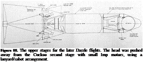
To improve performance further, a small solid fuel motor was added as a second stage. This was the Cuckoo – originally intended as a launch boost for the Skylark (the name apparently derived from the idea that the Cuckoo kicked the Skylark from out of its nest!). The original version was the Cuckoo IA, first flown in April 1960; the Cuckoo IB was identical apart from a changed interface from Skylark to Black Knight. It was replaced by the Cuckoo II, which had an improved performance. The Cuckoo would later go on to be developed further in extended versions of Skylark. The oddest feature is that the second stage is mounted pointing downwards. At the very top, under the jettisonable fairing, is a gas bottle with jets. This was used to spin up the Cuckoo motor after separation
from the main stage, which then coasted up to apogee then fell back to earth. An ionisation gauge was used to detect the start of the atmosphere, at which point the motor was fired. After motor cut off, the head was pushed away from the empty casing so that they would reenter separately.
 An even more elaborate system was used in later flights.
This involved a cradle which was referred to as a ‘sabot’
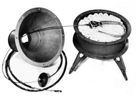
(French for ‘clog’, but in this context it has the artillery meaning of a device used in a firearm or cannon to fire a projectile which must be held in a precise position). The re-entry head was held in the sabot, which was attached to the Cuckoo motor by a long nylon rope. The aim was to propel the head well clear of the spent motor case.
The sabot system was necessary to keep the second stage re-entry out of the field of view of the instruments tracking the re-entry head. Separation took place at high altitude so as to give the head sufficient time to be at least 20,000 ft ahead of the second stage at 300,000 ft altitude. It was built on a magnesium alloy plate, on which there was an aluminium seat shaped to the re-entry head. It gave the head a velocity increment of the order of 400 ft/second using four Imp X motors. The thrust of the Imps blew off four panels on the separation bay, and in the case of BK20 it is possible that there was some interference at separation. Despite exhaustive ground testing on the range at Larkhill (Salisbury Plain) it was not possible to simulate the effects of vacuum and low temperature on the nylon.12
The lanyard as originally conceived consisted of 8 ft of steel wire followed by 120 ft of undrawn nylon. It was changed to 310 ft of slightly thinner nylon. The steel wire and first 20 ft of the nylon were covered with a woven asbestos sheath to protect it against the flame of the Imp motors, which had a burn time of a third of a second.
The final arrangement was sometimes and somewhat optimistically referred to as a three stage version: the Black Knight first stage, the Cuckoo second stage, and the Imp motors making the third stage. Starting at the top, below the nose cap is a gas bottle, which with attached jets, was used to spin the stage up. Below that is the Cuckoo motor, pointing Figure 87. The lanyard and sabot arrangement. downwards, then the sabot and lanyard arrangement, with the re-entry head itself at the very bottom.13
 As we shall see in the next chapter, the lanyard system was not always a success for a variety of reasons.
 |
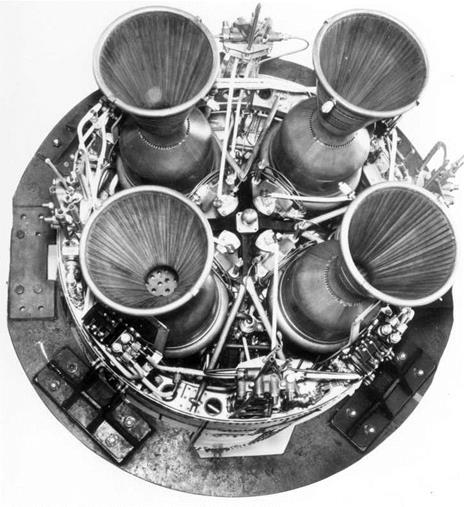
Changes to Black Knight were made incrementally throughout its life. The other major improvement was to replace the original rocket chambers with ones derived from the Stentor motor – the Stentor being developed by Armstrong Siddeley for the Blue Steel missile. The new chamber was lighter, but equally importantly, it was much easier to control the mixture ratio of HTP to kerosene in the new motor, making it more efficient. The maximum thrust was also greater – potentially 25,000 lb, but in practice an intermediate thrust level of 21,600 lb was used. The new motor was named the Gamma 301. A further refinement was proposed for the 54-inch Black Knight, the Gamma 304, which would have had only one turbine and pump feeding each chamber, rather than the four separate ones in the Gamma 301.
|
Figure 89. Gamma 301 motor using the small chamber from the Stentor motor. |
5 TNA: PRO AVIA 48/57. Black Knight: re-entry test vehicle. Saunders Roe Technical Publication 144.
6 Personal communication.
7 TNA: PRO AVIA 48/57. Black Knight: re-entry test vehicle.
8 TNA: PRO AVIA 6/21517. Black Knight electronic flash installation for optical tracking.
9 TNA: PRO AVIA 13/1269. ‘Black Knight’: body tests.
10 Ibid.
11 TNA: PRO AVIA 6/19890. Ballistic test vehicle Black Knight. (Technical Note Number G. W. 503, HGR Robinson.)
12 TNA: PRO AVIA 6/21754. Black Knight vehicles of project DAZZLE and their flight behaviour. RAE Technical Report 68076.
13 TNA: PRO DSIR 23/36396. The Black Knight vehicles of project DAZZLE and their flight behaviour.


