Category X-15 EXTENDING THE FRONTIERS OF FLIGHT

Fixed-Base Simulators

Simulation in the X-15 program meant much more than pilot training. It was perhaps the first program in which simulators played a major role in the development of an aircraft and its flight profiles. The flight planners used the simulators to determine heating loads, assess the effects of proposed technical changes, abort scenarios, and perform a host of related tasks. In this regard, the term "flight planner" at the AFFTC and FRC encompassed a great deal more than someone who sat down and wrote out a plan for a launch lake and a landing site. It is very possible that the flight planners (such as Elmore J. Adkins, Paul L. Chenoweth, Richard E. Day, Jack L. Kolf, John A. Manke, and Warren S. Wilson at the FRC, and Robert G. Hoey and Johnny G. Armstrong at the AFFTC) knew as much as (or more than) the pilots and flight-test engineers about the airplanes.-12!

The initial group of X-15 pilots worked jointly with research engineers and flight planners to

develop simulations to study the aspects of flight believed to present the largest number of potential difficulties. During late 1956, North American developed a fixed-base X-15 simulator at their Inglewood facility that consisted of an X-15 cockpit and an "iron bird" that included production components such as cables, push rods, bellcranks, and hydraulics. The iron bird looked more or less like an X-15 and used flight-representative electrical wiring and hydraulic tubing, but otherwise did not much resemble an aircraft. The simulator included a complete stability augmentation system (dampers), and ultimately added an MH-96 adaptive flight control system. Controlling the simulator were three Electronics Associates, Inc. (EAI) PACE 231R analog computers that contained 380 operational amplifiers, 101 function generators, 32 servo amplifiers, and 5 electronic multipliers. None of the existing digital systems were capable of performing the computations in real time, hence the selection of analog computers. The simulator could also compute a real-time solution for temperature at any one of numerous points on the fuselage and wing. Simulations were initiated in October 1956 using five degrees of freedom, and the simulator was expanded to six degrees of freedom (yaw, pitch, roll, and accelerations vertically, longitudinally, and radially) in May 1957.[3]

X-15 FLIGHT SIMULATION

Fixed-Base Simulators

Simulation in the X-15 program meant much more than pilot training and was the first program where simulators played a major role in the development of the aircraft and its flight profiles. Engineers used the simulators to determine heating loads, the effects of proposed technical changes, and to develop abort scenarios. Controlling the simulator were three Electronics Associates, Inc. (EAI) PACE 231R analog computers that contained 380 operational amplifiers, 101 function generators, 32 servo amplifiers, and 5 electronic multipliers. None of the existing digital systems was capable of performing the computations in real time, hence the selection of analog computers. (NASA)

The simulator covered Mach numbers from 0.2 to 7.0 at altitudes from sea level to 1,056,000 feet (200 miles), although it was not capable of providing meaningful landing simulations. The initial round of simulations at Inglewood showed that the X-15 could reenter from altitudes as high as 550,000 feet as long as everything went well. If done exactly right, a reentry from this altitude would almost simultaneously touch the maximum acceleration limit, the maximum dynamic pressure limit, and the maximum temperature limit. The slightest error in piloting technique would exceed one of these, probably resulting in the loss of the airplane and pilot. An angle of attack of 30 degrees would be required with the speed brakes closed, or only 18 degrees with the speed brakes open. The normal load factor reentering from 550,000 feet would reach 7 g, and a longitudinal deceleration of 4 g would last up to 25 seconds. Simulations in the centrifuge confirmed that pilots could maintain adequate control during these maneuvers, and considerations for the physical well-being of the pilot did not limit the flight envelope.-^

These first simulations indicated the need for a more symmetrical tail to reduce aerodynamic coupling tendencies at low angles of attack, and potential thrust misalignment at high velocities and altitudes. This resulted in the change from the vertical-stabilizer configuration proposed by North American to the one that was actually built. Reentry studies indicated that the original rate – feedback-damper configuration was not adequate for the new symmetrical tail, and an additional feedback of yaw-rate-to-roll-control (called "yar") was required for stability at high angles of attack.-51

Initially, the North American fixed-base simulator was computation-limited, and researchers could only study one flight condition at a time. The first three areas investigated were the exit phase, ballistic control, and reentry. Later, upgrades allowed complete freedom over a limited portion of a mission, and by mid-1957 unlimited freedom over the complete flight regime. By July 1958, the fixed-base simulator at North American already had over 2,000 simulated flights and more than 3,500 hours of experience under various flight conditions, and the airplane would not fly for another year.

As crude as it may seem today, the simulator nevertheless provided the flight planners with an excellent tool. The flight planner first established a detailed set of maneuvers that resulted in the desired test conditions. He then programmed a series of test maneuvers commensurate with the flight time available to ensure that the maximum amount of research data was obtained. Since the simulator provided a continuous real-time simulation of the X-15, it enabled the pilot to fly the planned mission as he would the actual flight, allowing him to evaluate the planned mission from a piloting perspective and to recommend changes as appropriate. Certain data, such as heating rates and dynamic pressures, required real-time computations to verify that the desired maneuvers were within the capability of the airplane.-61

Fixed-Base Simulators

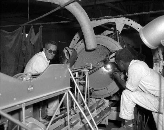
The fixed-base simulator at North American was hardly a fancy affair, just a mocked-up cockpit with a full set of instruments and a television screen. The original cadre of pilots, including Joseph A. Walker, spent a considerable amount of time in the North American simulator before the one at the Flight Research Center was ready. Although crude by today’s standards, the X-15 pioneered the use of simulators not just to train pilots, but also to engineer the aircraft, plan the missions, and understand the results. Not surprisingly, given the involvement of Charlie Feitz, Harrison Storms, and Walt Williams in both the X-15 and Apollo programs, the X-15 pointed the way to how America would conduct its space missions. (NASA)

Engineers also used the simulator to develop vehicle systems before committing them in flight. One of the most notable was the MH-96 adaptive flight control system. Exhaustive tests in the simulator, conducted largely by Neil Armstrong, allowed researchers to optimize system parameters and develop operational techniques. Similarly, engineers used the simulators to investigate problems associated with the use of the dampers, and devised modifications to install on the airplane. Researchers then incorporated the results of flight tests into the simulator.-171

(excepting the computers) to the FRC before turning the first airplane over to the government. Unlike the Inglewood installation, at the FRC the cockpit and analog computers were in the same room: not much to look at, but functional. The Air Vehicle Flight Simulation Facility was located in building 4800 at the FRC in an area that later became the center director’s office. Like many early computer rooms, it used a linoleum-covered plywood false floor to cover the myriad of cables running beneath it. Large air conditioners installed on the building roof kept the computers cool. The X-15 simulator used a set of EAI analog computers procured for earlier simulations at the FRC, including one model 31R, one 131R, and one 231R that were generally similar to the computers used by North American. John P. Smith had begun mechanizing the original equations in the simulator, but Gene L. Waltman completed the task during the last three months of 1960 after Smith was promoted to a new job. The X-15 simulator became operational at the FRC on 3 January 1961. The X-15 simulator was the largest analog simulation ever mechanized at the FRC. The initial Air Vehicle Flight Simulation Facility at the FRC cost $63,000 and upgrades accounted for a further $1,700,000 by the end of 1968.-8

Because the FRC simulator was not yet operational, the flight planning for the first 20 flights used the North American simulator. Dick Day and Bob Hoey spent a considerable amount of time during 1959 and 1960 in Inglewood on flight planning and training the first cadre of pilots.-9 Initially, North American was to transfer the simulator from Inglewood to the FRC in January 1961, but the move was delayed for various reasons, including the need to integrate the MH-96 adaptive flight control system into X-15-3. By March 1961, however, Paul Bikle was becoming concerned: "With the performance envelope expansion program now underway, the requirement of traveling to NAA [North American Aviation] to use the X-15 simulator is becoming unduly restrictive in time and in obtaining the close working relationships essential to a sound flight panning effort." Something needed to change.-10

Bikle knew that North American did not want to transfer the simulator until the MH-96 integration was complete. In an effort to determine the consequences of moving earlier, Bikle called Dave Mellon at Minneapolis-Honeywell, who said he did not think the move would have an adverse affect on his schedule. Bikle also commented that "if a program delay is inevitable, it is preferable to delay the X-15-3 rather than the present program with the X-15-2." Bikle pushed to have the simulator moved to the FRC during April 1961. "We again want to emphasize that once the transfer has been accomplished, the NASA will make the simulator available for whatever additional simulator effort is required by NAA, M-H [Minneapolis-Honeywell], and other contractors…."-19

Fixed-Base Simulators

At first, the Flight Research Center made do with the crude cockpit that had been used in the centrifuge at NADCJohnsville. This was a cost-saving measure since the X-15 contract required North American to deliver their simulator (excepting the computers) to the FRC before turning the first airplane over to the government. Unlike the Inglewood installation, the cockpit and analog computers were in the same room at the FRC. The Air Vehicle Flight Simulation Facility was located in Building 4800 at the FRC in an area that later became the center director’s office. (NASA)

When the iron bird finally arrived in April 1961, engineers installed it along the east wall of the calibration hangar next door to the computer facility. A wall around the simulator provided some separation from the operations in the hangar. The cockpit faced away from the hangar door, and pilots discovered that sunlight coming through the windows caused visibility issues, so paint soon covered the windows. One of the unfortunate aspects of this installation was that the iron bird was located a little over 200 feet from the computers. This caused a number of signal-conditioning problems that a better grounding system eventually corrected. The hydraulic stand for the iron bird was originally located next to the mockup inside the hangar, but technicians subsequently relocated the unit to a small shed just outside, eliminating most of the noise from the simulator laboratory.-1121

To provide simulations that were more realistic, engineers at the FRC added a "malfunction generator" that could simulate the failure of 11 different cockpit instruments and 23 different aircraft systems. The instruments included a pressure altimeter, all three attitude indicators, and pressure airspeed, dynamic pressure, angle-of-attack, angle-of-sideslip, inertial altitude, inertial velocity, and inertial rate-of-climb indicators. The vehicle systems that could be failed included the engine, ballistic control system, both electrical generators, and any axis in the damper system. Later, the simulator could duplicate the failure of almost any function of the MH-96 adaptive control system. Almost all X-15 flights were preceded by practicing various emergency

procedures in the simulator using these malfunction generators.-1131

Fixed-Base Simulators

The final simulator at the Flight Research Center was functionally identical to the one at North American, and used the same analog computers. The structure behind the cockpit is the "iron bird" that included production components such as cables, push rods, bellcranks, and hydraulics. The iron bird looked more or less like an X-15 and used flight-representative electrical wiring and hydraulic tubing, but otherwise did not much resemble an aircraft. The simulator included a complete stability augmentation system (dampers), and ultimately added an MH-96 adaptive flight control system. (NASA)

Contrary to many depictions of flight simulators in movies, the fixed-base simulator for the X-15 was not glamorous. The iron bird stretched behind the cockpit, but other than in size, it did not resemble an X-15 at all. The cockpit was open, and the sides of the "fuselage" extended only high enough to cover the side consoles and other controls inside of it. A canopy over the cockpit became necessary when researchers installed some instruments and controls (particularly for the experiments) there for later flights, but even then, it was made of plywood.-141

However, unlike most of the previous simulators at the FRC, the X-15 cockpit did have an accurate instrument panel. On one occasion, technicians inadvertently switched the location of the on/off switches for the ballistic control system and the APUs between the simulator and the airplane. It was normal procedure for the pilot to turn off the ballistic controls after reentry, and he practiced this in the simulator before each flight. During the actual flight, the pilot reached for the APU switch instead of the switch he thought was there. Fortunately, he caught himself and avoided an emergency. Everybody redoubled their efforts to ensure that the simulator accurately reflected the configuration of the airplane.15

When X-15-3 came on line with a completely different instrument panel arrangement, it presented some challenges for the simulator. Since the pilots needed to train on the correct instrument panel layout, the simulator support personnel had to swap out instrument panels to accommodate each different airplane. The technicians eventually installed a crank and pulley lift in the ceiling, along with cannon plugs for the electrical connections, to assist in making the change. On at least three occasions the program decided to make the instrument panels in the three airplanes as similar as possible, but they quickly diverged again as new experiments were added.1161

In addition to its simulation tasks, the iron bird found another use as the flight program began. Engineers and technicians at the FRC soon discovered that it was a relatively simple task to remove troublesome components from the flight vehicles and install them on the iron bird in an attempt to duplicate reported problems. Given the initial lack of test equipment available for the stability augmentation system and some MH-96 components, this proved a useful troubleshooting method. The simulator also played an important role in demonstrating the need for advanced display and guidance devices, and found extensive use in the design and development of new systems.-1171

The simulator had a variety of output devices in addition to the cockpit displays, including several eight-channel stripchart recorders and a large X/Y flatbed plotter. The plotter had two independent pens: one showed the X-15 position on a 3-foot-square map of the area, and the other indicated altitude. This plotter was identical to ones used in the control room and at the uprange stations. There were different maps for each launch lake showing the various contingency landing sites and prominent landmarks.1181

Eventually the FRC simulator grew to encompass six analog computers, and the patch panels needed to operate them contained 500 patch cords. The addition of a Scientific Data Systems SDS-930 digital computer in 1964 allowed the generation of nonlinear coefficients for the X – 15A-2. This required an additional analog computer as an interface between the new digital computer and the rest of the simulator. The SDS-930 was somewhat unusual in that it was a true real-time computer, complete with a real-time operating system and a real-time implementation of Fortran.1191

Despite its advanced specifications the SDS-930 was not initially satisfactory, which forced the flight planners to use the modified Dyna-Soar hybrid simulator at the AFFTC for the early X-15A – 2 flights. The SDS-930 was generally unreliable, normally because of memory-parity errors that the computer manufacturer attempted to fix on numerous occasions during 1965, with little success. The problem was not only affecting flight planning for the X-15A-2, it was also delaying simulations needed for the energy-management system scheduled to fly on X-15-3. During early 1966, the SDS-930 was extensively modified to bring it up to the latest configuration, including the addition of two magnetic-tape units and a line printer to assist in the energy-management simulations. While this was going on, the FRC took advantage of the downtime to upgrade the SAS and ASAS implementation on the iron bird, including replacing all of the computer interface equipment for both systems. Technicians also brought all of the mechanical rigging up to the same standard as the three airplanes. However, Johnny Armstrong and Bill Dana both recall that no actual flight planning or flight simulation was "totally digital."1201

The hybrid (analog-digital) simulator at the AFFTC initially provided a tool that enabled studies of the performance and handling of the X-20 glider, complete mission planning, and pilot familiarization. It was a logical outgrowth of the analog fixed-base simulators for the X-15. Although they had been ordered long before, the digital computers did not arrive at Edwards until

July 1964, six months after the cancellation of the Dyna-Soar program. The equipment sat mostly unused until the flight planners decided to adapt it to the X-15A-2 Mach 8 flight expansion program. This was done as much to provide Air Force personnel with some hands-on experience as for any demonstrated need for another X-15 simulator.-1211

The analog section of the hybrid simulator used PACE 231R-V and 231R computers similar to those used at the FRC and North American installations. Each computer had approximately 75 operational amplifiers, 170 potentiometers, 36 digitally controlled analog switches, and 26 comparators, and the 231R-V had a mode-logic group that supported an interface to a digital computer. The digital subsystem used a Control Data Corporation DDP-24 that had 8,192 words of ferrite core memory, a 5-microsecond access time, and a 1-MHz clock. Although a Fortran II compiler was available on the machine, engineers coded the real-time programs in assembly language to maximize the performance of the relatively slow machines. Two large patch panels connected the analog subsystem and digital subsystem.-1221

Fixed-Base Simulators

The fixed-base simulators at Inglewood and the FRC consisted of four major parts. The simulator included both controls and displays that were nearly identical to what the pilot found in the X-15 cockpit. The analog computer and malfunction generator were the heart of the system that provided the sequencing and control of the other components. The hydraulic control system was the "iron bird" and actually contained other flight components in addition to the hydraulic system including a complete stability augmentation system (or, later, a complete MH-96 adaptive flight control system). (NASA)

Like the other fixed-base simulators, the AFFTC device had a functional X-15 instrument panel, although it was not as exact as the ones used at the FRC. This was because its intended use was to investigate heating and control problems related to the X-15A-2, not to conduct pilot training. Ultimately, the program did use the AFFTC simulator for some X-15A-2 pilot training, but the final "procedures" training was conducted at the FRC.

Since the X-15 program technically did not need the simulator, the AFFTC engineers were able to develop a "generic" simulation that was usable for other aircraft, not just the X-15. This was an extremely astute idea, and the engineers subsequently used the simulator for the M2-F2, SR-71, X-24A, X-24B, and EF-111. The hybrid simulator was also the only one available to perform heating predictions during reentry simulations of the Space Shuttle Orbiter during the early 1970s, providing valuable input to that program.-123

At the FRC, the simulation team kept busy maintaining the computers and updating the programming to reflect actual flight results. During most of the flight program the simulation lab was busy for at least two shifts, and often three shifts, per day. The first shift performed pilot training and flight planning, the second shift conducted control-system and other studies, and maintenance and reprogramming occupied the third shift as needed. However, the team generally took weekends off. This was not necessarily a good thing for the simulator since it took the analog computers quite a while on Monday morning to warm up.-123

Despite the apparent success of the fixed-base simulators, everybody recognized their limitations. The primary concern was that they were fixed-base and not motion-base, and therefore were inappropriate for landing training. For instance, the lack of a high-quality visual presentation meant that critical visual cues were not available to the pilots. The analog computer also had limitations. For example, the precision needed to calculate altitude and rate of climb for the landing phase was not readily achievable with the parameter scaling used for the rest of the flight. The parameter scaling was critical, and analog computers were accurate to about one part in 10,000. For the X-15 simulation, with the altitude scaled such that 400,000 feet equaled 100 volts, one-tenth of a volt was equal to 40 feet. Any altitude less than this was down in the noise of the analog components and barely detectable. It was simply not possible to calculate accurate altitudes for the landing phase and the rest of the flight profile at the same time. All of this necessitated maintaining a fleet of Lockheed F-104 Starfighters as landing trainers, something the X-15 pilots did not seem to mind at all.-123

Nevertheless, Larry Caw and Eldon Kordes did mechanize a simple four-degrees-of-freedom simulation to study landing loads early in the program. The simulation only covered the last few seconds of a flight, and was not particularly useful as a pilot training tool. However, it allowed Jack McKay and other engineers to look at the variety of forces generated during an X-15 landing, and prompted the first round of landing-gear changes on the airplane.-126

The lack of a motion-base simulator presented several interesting problems. For instance, some phenomena experienced in the JF-100C variable-stability airplane during the summer of 1961 indicated that using the beta-dot technique in the X-15 might be more difficult than anticipated. Consequently, a cooperative program was initiated with NASA Ames to use its three-axis motion – base simulator. The objective was to investigate further the effect of g-loading on the pilot while he performed beta-dot recovery maneuvers. Four pilots-Forest Petersen, Bob Rushworth, Joe

Walker, and Bob White-participated in the tests during September 1961. Paul Bikle reported that, "With fixed-base simulation, the ventral-on condition was uncontrollable, using normal techniques; however, it could be controlled by using the special beta-dot control technique. With the moving cockpit simulation, control using either normal or beta-dot techniques was more difficult for the pilot than with the fixed-base cockpit simulation. These results were in general agreement with the ground and flight tests conducted with the variable-stability F-100 airplane."271

By the end of the X-15 program, the FRC had established simulation as an integral part of the flight program. Today, the Walter C. Williams Research Aircraft Integration Facility (RAIF) provides a state-of-the-art complex of computers, simulators, and iron-bird mockups. As an example of the extent to which simulations were used, during the X-33 program, pilot Stephen D. Ishmael flew countless missions while engineers evaluated vehicle systems, flight profiles, and abort scenarios. What is ironic is that the X-33 was to be an unmanned vehicle— Ishmael was just another computing device, one with a quick sense of reason and excellent reflexes.

HYPERSONICS

Hypersonic. Adj. (1937). Of or relating to velocities in excess of five times the speed of sound.-132

Between the two world wars, hypersonics was an area of great theoretical interest to a small group of aeronautical researchers, but little progress was made toward defining the possible problems, and even less in solving them. The major constraint was power. Engines, even the rudimentary rockets then available, were incapable of propelling any significant object to hypersonic velocities. Wind tunnels also lacked the power to generate such speeds. Computer power to simulate the environment had not even been imagined. For the time being, hypersonics was something to be contemplated, and little else.

By the mid-1940s it was becoming apparent to aerodynamic researchers in the United States that it might finally be possible to build a flight vehicle capable of achieving hypersonic speeds. It seemed that the large rocket engines developed in Germany during World War II might allow engineers to initiate development with some hope of success. Indeed, the Germans had already briefly toyed with a potentially hypersonic aerodynamic vehicle, the winged A-4b version of the

V-2 rocket. The only "successful" A-4b flight had managed just over Mach 4 (about 2,700 mph) before apparently disintegrating in flight.[33] Perhaps unsurprisingly, in the immediate post-war period most researchers believed that hypersonic flight was a domain for unmanned missiles.134

When the U. S. Navy BuAer provided an English translation of a technical paper by German scientists Eugen Sanger and Irene Bredt in 1946, this preconception began to change. Expanding upon ideas conceived as early as 1928, Sanger and Bredt concluded in 1944 that they could build a rocket-powered hypersonic aircraft with only minor advances in technology. This concept of manned aircraft flying at hypersonic velocities greatly interested researchers at the NACA. Nevertheless, although there were numerous paper studies exploring variations of the Sanger – Bredt proposal during the late 1940s, none bore fruit and no hardware construction was undertaken.1351

One researcher who was interested in exploring the new science of hypersonics was John V.

Becker, the assistant chief of the Compressibility Research Division at the NACA Langley Aeronautical Laboratory in Hampton, Virginia.-1361 On 3 August 1945, Becker proposed the construction of a "new type supersonic wind tunnel for Mach number 7." Already a few small supersonic tunnels in the United States could achieve short test runs at Mach 4, but the large supersonic tunnels under construction at Langley and Ames had been designed for Mach numbers no higher than 2. Information captured by the Army from the German missile research facility at Peenemunde had convinced Becker that the next generation of missiles and projectiles would require testing at much higher Mach numbers.-1371

As the basis for his proposed design, Becker extrapolated from what he already knew about supersonic tunnels. He quickly discovered that the compressible-flow theory for nozzles dictated a 100-fold expansion in area between Mach 1 and Mach 7. Using normal shock theory to estimate pressure ratio and compressor requirements, Becker found that at Mach 7 the compressor system would have to grow to impractical proportions.1381

Hope for alleviating the compressor problem had first appeared in the spring of 1945 when Becker gained a fresh understanding of supersonic diffusers from a paper by Arthur Kantrowitz and Coleman duPont Donaldson.1391 The paper focused on low-Mach-number supersonic flows and did not consider variable geometry solutions, but it was still possible to infer that changing the wall contours to form a second throat might substantially reduce the shock losses in the diffuser. Unfortunately, it appeared that this could only be accomplished after the flow had been started, introducing considerable mechanical complexity. The potential benefits from a variable – geometry configuration were inconsequential at Mach 2, but Becker determined that they could be quite large at Mach 7. In the tunnel envisioned by Becker, the peak pressure ratios needed to start the flow lasted only a few seconds and were obtained by discharging a 50-atmosphere pressure tank into a vacuum tank. Deploying the second throat reduced the pressure ratio and power requirements, allowing the phasing-in of a continuously running compressor to provide longer test times. It was a novel concept, but a number of uncertainties caused Becker to advise the construction of a small pilot tunnel with an 11 by 11-inch test section to determine experimentally how well the scheme worked in practice.1401

HYPERSONICS

John V. Becker was the lead of the NACA Langley team that accomplished much of the preliminary work needed to get a hypersonic research airplane approved through the NACA Executive Committee and Department of Defense. Becker continued to play an import role with the X-15 throughout the development and flight programs. (NASA)

Not everybody agreed that such a facility was necessary. The NACA chairman, Jerome C. Hunsaker,[41] did not see any urgency for the facility, and Arthur Kantrowitz, who designed the first NACA supersonic wind tunnel, did not believe that extrapolating what little was known about supersonic tunnels would allow the development of a hypersonic facility. The most obvious consequence of the rapid expansion of the air necessary for Mach 7 operation was the large drop in air temperature below the nominal liquefaction value. At the time, there was no consensus on the question of air liquefaction, although some preliminary investigations of the condensation of water vapor suggested that the transit time through a hypersonic nozzle and test section might be too brief for liquefaction to take place. Nevertheless, Kantrowitz, the head of Langley’s small gas-dynamics research group, feared that "real-gas effects"—possibly culminating in liquefaction —would probably limit wind tunnels to a maximum useful Mach number of about 4.5.[42

Nevertheless, Becker had his supporters. For instance, Dr. George W. Lewis,[43] the Director of Aeronautical Research for the NACA, advised Becker, "Don’t call it a new wind tunnel. That would complicate and delay funding," so for the next two years it was called "Project 506." The estimated $39,500 cost of the pilot tunnel was rather modest, and given Lewis’s backing, the facility received quick approval.[44]

In September 1945 a small staff of engineers under Charles H. McLellan began constructing the facility inside the shop area of the old Propeller Research Tunnel. They soon discovered that Kantrowitz’s predictions had been accurate—the job required more than extrapolation of existing supersonic tunnel theory. The pilot tunnel proposal had not included an air heater, since Becker believed he could add it later if liquefaction became a problem. As work progressed, it became increasingly clear that the ability to control air temperature would greatly improve the quality and scope of the research, and by the end of 1945 Becker had received approval to include an electric

heater. This would maintain air temperatures of about 850°F, allowing Mach 7 temperatures well above the nominal liquefaction point.[45]

The first test of the "11-inch" on 26 November 1947 revealed uniform flow at Mach 6.9, essentially meeting all of the original intents. An especially satisfying result of the test was the performance of the variable-geometry diffuser. McLellan and his group had devised a deployable second throat that favored mechanical simplicity over aerodynamic sophistication, but was still very effective. The benefit appeared as an increased run duration (in this case an increase from 25 seconds to over 90 seconds).[46]

For three years the 11-inch would be the only operational hypersonic tunnel in the United States and, apparently, the world. Several basic flow studies and aerodynamic investigations during this period established the 11-inch as an efficient tool for general hypersonic research, giving Langley a strong base in the new field of hypersonics. Without this development, Langley would not have been able to define and support a meaningful hypersonic research airplane concept in 1954. Throughout the entire X-15 program, the 11-inch would be the principal source of the necessary hypersonic tunnel support.[47]

HYPERSONICS

The 11-inch at NACA Langley was intended as a pilot tunnel for a larger hypersonic wind tunnel when it opened in 1947. However, it proved so useful that it stayed in service until 1973, and the research documented in it resulted in over 230 publications. Much of the early work on what became the X-15 was accomplished in this wind tunnel. (NASA)

decommissioned, NASA donated the tunnel to the Virginia Polytechnic Institute in Blacksburg, Virginia.1481

As the 11-inch tunnel at Langley was demonstrating that it was possible to conduct hypersonic research, several other facilities were under construction. Alfred J. Eggers, Jr., at the NACA Ames Aeronautical Laboratory at Moffett Field, California,1491 began to design a 10 by 14-inch continuous-flow hypersonic tunnel in 1946, and the resulting facility became operational in 1950. The first hypersonic tunnel at the Naval Ordnance Facility, constructed largely from German material captured from the uncompleted Mach 10 tunnel at Peenemunde, also became operational in 1950.1501

Interestingly, NASA did not authorize a continuously running hypersonic tunnel that incorporated all of the features proposed in the 1945 Becker memo until 1958. Equipped with a 1,450°F heater, the design velocity increased from Becker’s proposed Mach 7 to 12. As it ended up, although the tunnel attained Mach 12 during a few tests, severe cooling problems in the first throat resulted in a Mach 10 limit for most work. The enormous high-pressure air supply and vacuum tankage of the Gas Dynamics Laboratory provided blow-down test durations of 10-15 minutes. Together with improved instrumentation, this virtually eliminated the need to operate the tunnel in the "continuously running" mode, and nearly all of Langley’s "continuous-running" hypersonic tunnel operations have been conducted in the "blow-down" mode rather than with the compressors running.1511

THE FIRST INDUSTRY CONFERENCE (1956)

The public law that established the NACA required the agency to disseminate information to the industry and the public. One of the methods used to accomplish this was to hold periodic conferences with representatives of the industry to discuss the results of research into specific areas. By the beginning of July, Hugh Dryden concluded there had been sufficient progress on the development of the X-15 to hold an industry conference at one of the NACA facilities in October.-411

Langley hosted the first Conference on the Progress of the X-15 Project on 25-26 October 1956, providing an interesting insight into the X-15 development effort. There were 313 attendees representing the Air Force, NACA, Navy, various universities and colleges, and most of the major aerospace contractors. Approximately 10% of the attendees were from various Air Force organizations, with the WADC contributing over half. Oddly, however, Air Force personnel made none of the presentations at the conference. The majority of the 27 authors of the 18 technical papers came from various NACA organizations (16), while the rest were from North American (9) and Reaction Motors (2). The papers confirmed a considerable amount of progress, but made it clear that a few significant problems still lay ahead.-42

Another paper summarized the results of tests in eight different wind tunnels. These tests were conducted at velocities between low subsonic speeds to Mach 6.9, somewhat in excess of the projected maximum speed of the airplane. One of the surprising findings was that the controversial fuselage tunnels generated nearly half of the total lift at high Mach numbers. However, another result confirmed the NACA prediction that the original fuselage tunnels would cause longitudinal instability. In subsequent testing, researchers shortened the tunnels ahead of the wing, greatly reducing the problem.-43

One of the more interesting experiments was "flying" small (3- to 4-inch) models in the hypervelocity free-flight facility at Ames. The models, which were made of cast aluminum, cast bronze, or various plastics, were fragile. Despite this, the goal was to shoot the model out of a gun at tremendous speeds in order to observe shock-wave patterns across the shape. As often as not, what researchers saw were pieces of X-15 models flying down the range sideways. Fortunately, enough of the models remained intact for them to acquire meaningful data.-444

THE FIRST INDUSTRY CONFERENCE (1956)

The hypervelocity free-flight facility at NACA Ames fired small (3-4-inch-long) models of the X – 15 to observe shock-wave patterns. It was more of an art than a science to get the models to fly forward and not break apart, but enough survived to gain significant insight into shock patterns surrounding the X-15. (NASA)

Other papers dealt with the ability of the pilot to fly the airplane. Pilots had flown the preliminary exit and reentry profiles using fixed-base simulators at Langley and North American. Alarmingly, the pilots found that the airplane was nearly uncontrollable without damping and only marginally stable during some maneuvers with dampers. A free-flying model program at the PARD showed that low-speed stability and control were adequate. Since some aerodynamicists had questioned the use of the rolling tail instead of ailerons, free-flying models had investigated that feature, proving that the rolling tail would provide the necessary lateral control.[45]

Researchers also reported on the state of the structural design. Preliminary estimates showed that the airplane would encounter critical loads during the initial acceleration and during reentry, but would experience maximum temperatures only during the latter. Because of this, the paper primarily dealt with the load-temperature relationships anticipated for reentry. The selection of Inconel X was justified based on its strength and favorable creep characteristics at 1,200°F. The leading edge would use a bar of Inconel X, since that portion of the wing acted as a heat sink. This represented a radical change from the fiberglass leading edge originally proposed by North American. In another major change, the leading edge of the wing was no longer easily removable, although this fact seemed to escape the attention of most everybody in attendance, particularly Harry Goett from Ames.[46]

The main landing gear brought its own concerns. Originally, it consisted of two narrow skids attached to the fuselage under the front part of the wing and stowed externally along the side tunnels during flight. When unlocked, the skis fell into the down position, with help from airflow and a bungee. Further analysis indicated that the X-15 would land more nose-high than expected, and that the rear fuselage would likely strike the ground before the skids. A small tail – skid had been proposed, but this was found to be inadequate. In its place, engineers moved the skids aft to approximately the leading edge of the vertical stabilizers, solving the ground-strike problem. However, the move introduced a new concern. Now the nose-down rotation after main – skid contact would be particularly jarring, placing a great deal of stress on the pilot and airframe. In fact, it would lead directly to one early landing accident and be a source of problems throughout the flight program. Nobody had a suitable solution.[47]

The expected acceleration of the X-15 presented several unique human-factor concerns early in the program. It was estimated that the pilot would be subjected to an acceleration of up to 5 g. Because of this, North American developed a side-stick controller that used an armrest to support the pilot’s arm while still allowing full control of the airplane. Coupled with the fact that there were two separate attitude-control systems on the X-15, this resulted in a unique control-stick arrangement. A conventional center stick, similar to that installed in most fighter-type aircraft of the era, operated the aerodynamic control surfaces through the newly required stability augmentation (damper) system. Mechanical linkages connected a side-stick controller on the right console to the same aerodynamic control surfaces and augmentation system. The pilot could use either stick interchangeably, although the flight manual described the use of the center stick "during normal periods of longitudinal and vertical acceleration." Another side-stick controller above the left console operated the ballistic control system that provided attitude control at high altitudes. Describing one of the phenomena soon to be discovered in space flight, the flight manual warned that "velocity tends to sustain itself after the stick is returned to the neutral position. A subsequent stick movement opposite to the initial one is required to cancel the original attitude change." Isaac Newton was correct after all.[48]

THE FIRST INDUSTRY CONFERENCE (1956)

From the left, North American test pilot Alvin S. White, Air Force X-15 Project Pilot Captain Iven C. Kinchloe, and Scott Cross field discuss the design of the side stick controller for the new research airplane. The design of these controllers caused quite a bit of controversy early in the program, but the pilots generally liked them once they acclimated. Crossfield’s influence on the program showed early in the flight program when some pilots complained the configuration of the cockpit was tailored to Crossfield’s size and was not sufficiently adjustable to accommodate other pilots. Later modifications solved these issues. (Alvin S. White Collection)

Engineers had not firmly established the design for the X-15 side-stick controller, but researchers discussed previous experience with similar controllers in the Convair F-102, Grumman F9F, Lockheed TV-2, and North American YF-107A, as well as several ground simulators. The pilots who had used these controllers generally thought that the engineers needed to provide a more "natural" feel for the controllers.-49

Based largely on urgings from Scott Crossfield, the Air Force agreed to allow North American to use an ejection seat instead of a capsule system. The company had investigated four escape systems in depth, including cockpit capsules, nose capsules, a canopy-shielded seat, and a stable-seat with a pressure suit. Engineers had tried capsule-like systems before, most notably in the X-2, where the entire forward fuselage could be detached from the rest of the aircraft.

Douglas had opted for this approach in all of the D-558s and their X-15 proposal. Model tests showed that these were unstable and prone to tumble at a high rate of rotation, and they added weight and complexity to the aircraft. Their potential success rate was unknown at the time.-501

THE FIRST INDUSTRY CONFERENCE (1956)

North American performed a seemingly endless series of analyses to support their selection of an ejection seat over an encapsulated system. The company determined there was only a 2-percent likelihood of an accident occurring at high altitude or high speed, eliminating much of the perceived need for the complicated and heavy encapsulated system. The stabilized ejection seat, coupled with the David Clark Company full-pressure suit, provided meaningful ejection up to Mach 4 and 120,000 feet. (North American Aviation)

Surprisingly, an analysis by North American showed that only 2% of the accidents would occur at high altitude or speed. Because engineers expected most potential accidents to occur at speeds less than Mach 4, North American had decided to use a stable-seat with a pressure suit. The perceived benefits of this combination were its relative simplicity, high reliability, and light weight. North American acknowledged that the seat did not provide meaningful escape at altitudes above 120,000 feet or speeds in excess of Mach 4. However, the designers (particularly Scott Crossfield) believed that when the seat-suit combination was inadequate, the safest course of action was for the pilot to simply ride the airplane down to an altitude and velocity where the ejection seat could function successfully.-1511

Lawrence P. Greene, the chief of aerodynamics at North American, presented the final paper at the 1956 industry conference. This was an excellent summary of the development effort to date and a review of the major known problems. Researchers considered flutter to be a potential problem, largely because little experimental data regarding flutter at hypersonic Mach numbers were available, and there was a lack of basic knowledge on aero-thermal-elastic relationships. Greene pointed out that engineers had derived the available data on high-speed flutter from experiments conducted at less than Mach 3, and not all of it was applicable to the X-15. As it turned out, the program did encounter panel flutter during the early flights, leading to a change in the design criteria for high-speed aircraft.-152

Inconel X also presented a potential problem because fabrication techniques for large structures did not exist. By using various alloys of titanium, North American saved considerable weight in parts of the internal structure that were not subject to high temperatures. Titanium, while usable to only about 800°F, weighed much less than Inconel X. Ultimately, the requirements for processing and fabricating these materials influenced some aspects of the structural design. Inconel X soon stopped being a laboratory curiosity as the X-15 program developed techniques to form, machine, and heat-treat it.[53]

Overall, the conference was a success and disseminated a great deal of information to the industry, along with frank discussions about unresolved issues and concerns. It also provided a short break for the development team that had been working hard to meet an extremely ambitious schedule.

THE 1956 INDUSTRY CONFERENCE

The XLR99 presented several unique challenges to Reaction Motors. Perhaps the major one was that the engine was being developed for a manned vehicle, which entailed more safety and reliability requirements than unmanned missiles. However, perhaps even more challenging were the requirements to be able to throttle and restart the engine in flight-something that had not yet been attempted with a large rocket engine. The Reaction Motor representative at the 1956 industry conference concluded his presentation with the observation that developing the XLR99 was going to be challenging. Subsequent events proved this correct.-138

Подпись: TURBINE THRUSTПодпись:

THE 1956 INDUSTRY CONFERENCE Подпись: MA N LOX

Robert W. Seaman from Reaction Motors presented preliminary specifications for the XLR99-RM-1 at the conference. The oxygen-ammonia engine could vary its thrust from 19,200 lbf (34%) to 57,200 lbf at 40,000 feet, and had a specific impulse between 256 seconds and 276 seconds depending on the altitude and throttle setting. The engine fit into a space 71.7 inches long and 43.2 inches in diameter. At this point, Reaction Motors was predicting a 618-pound dry weight and a 748-pound gross weight. A two-stage impulse turbine drove the single-inlet oxidizer pump and two-inlet fuel pump. The hydrogen-peroxide-driven turbopump exhausted into the thrust chamber. Regulating the amount of hydrogen peroxide that was decomposed to drive the turbopump provided the throttle control.-139

LOX

i—cm

lOX ‘

ACCUMULATOR

Подпись: POWER CONSOL Подпись: IGNITER MART THE 1956 INDUSTRY CONFERENCE THE 1956 INDUSTRY CONFERENCE

Подпись:

THE 1956 INDUSTRY CONFERENCE
Подпись: POOPEUAHT VALVE

GENERATOR

THE 1956 INDUSTRY CONFERENCEBASIC ENGINE SCHEMATIC

Although not the most powerful rocket engine of its era, the XLR99 was the most advanced and used a sophisticated turbopump to supply liquid oxygen and anhydrous ammonia propellants to the combustion chamber. The engine was capable of being restarted in flight, an unusual feature for the time (or even today) and numerous safety systems automatically shut down the engine in the event of a problem. (NASA)

Engineers decided to control thrust by regulating the speed of the turbopump because the other possibilities resulted in the turbopump speeding up as pressure decreased, resulting in cavitation. Controlling the propellant to the turbopump also required fewer controls and less instrumentation. However, varying the fuel flow led to other issues, such as how to provide adequate coolant (fuel) to the thrust chamber.[40]

The engineers also had to give engine compartment temperatures more consideration than they did for previous engines due to the high heat transfer expected from the X-15 hot-structure. This was one of the first instances in which the surrounding airframe structure would be hotter than the engine. Since North American was designing the hot structure of the X-15 to withstand temperatures well in excess of those the engine produced, the engineers were not planning to insulate the engine compartment.-41

Another paper discussed engine controls and instruments, accessory installation, and various propellant system components. The 1,000-gallon liquid-oxygen tank was located just ahead of the aircraft center of gravity, and the 1,400-gallon anhydrous-ammonia tank was just behind it. A 3,600-psi helium supply tube within the liquid-oxygen tank supplied the gas to pressurize both tanks. A 75-gallon hydrogen-peroxide tank behind the ammonia tank provided the monopropellant for the turbopump, using a small, additional supply of helium.-421

The liquid-oxygen and ammonia tanks had triple compartments arranged to force the propellants toward the center of gravity during normal operations and during jettisoning. The design needed to compensate for the acceleration of the X-15, which tended to force propellants toward one end of the tanks or the other. Further complicating the design of the tanks was the necessity for efficient loading and minimizing the remaining propellant after burnout or jettisoning.

Fortunately, the tanks did not present any insurmountable problems during early tests.-431

Because the engineers did not yet fully understand the vibration characteristics of the XLR99, they designed a rigid engine mount without any special vibration attenuation. The engine-mount truss attached to the fuselage at three fittings, and by adjusting the lower two fittings the engineers could tailor the thrust vector of the engine. Three large removable doors in the aft fuselage provided access to the engine and allowed closed-circuit television cameras to observe the engine during ground testing. Ultimately, this mounting technique would also make it much easier to use the interim XLR11 engines.-441

The Wheel

The Navy, an otherwise silent partner, made a notable contribution to flight simulation for the X – 15 program. Primarily, the Aviation Medical Acceleration Laboratory (AMAL) at NADC Johnsville provided a unique ground simulation of the dynamic environment.-1281

Even prior to the beginning of World War II, researchers recognized that acceleration effects experienced during high-speed flight would require evaluation, and by 1944 the BuAer became convinced that it would require a long-term commitment to understand such effects completely. The centerpiece of what became the AMAL was a new $2,381,000 human centrifuge. Work on the facility at Johnsville began in June 1947, with the McKiernan-Terry Corporation of Harrison, New Jersey, constructing the centrifuge building under the direction of the Office of Naval Research.

The chief of naval operations established the AMAL on 24 May 1949, and during validation of the facility on 2 November 1951, Captain J. R. Poppin, the director of AMAL, became the first human to be tested in the centrifuge.-291

When the facility officially opened on 17 June 1952, it was the most sophisticated of its kind in the world, and was capable of producing accelerations up to 40 g to investigate the reaction of pilots to accelerations. A 4,000-horsepower vertical electric motor in the center of the room drove the centrifuge arm. Depending on the exact requirements of the test, researchers could position a gondola suspended by a double gimbal system at one of several locations along the arm. The outer gimbal permitted rotation of the gondola about an axis tangential to the motion of the centrifuge, while the inner gimbal allowed rotation about the axis at right angles to the tangential motion. Separate 75-horsepower motors connected through hydraulic actuators controlled the angular motions of the gondola, and continuous control of the two axes in combination with rotation of the arm produced somewhat realistic high-g accelerations for the pilot.201

Initially, electromechanical systems controlled the centrifuge since general-purpose computers did not, for all intents, yet exist. In the centrifuge, large Masonite discs called "cams" controlled the acceleration along the three axes. A series of cam followers drove potentiometers that generated voltages to control the various hydraulic actuators and electric motors. The cams had some distinct advantages over manual control: they automated complex motions and allowed precise duplication of the motions. However, the process of cutting the Masonite discs amounted to little more than trial and error, and technicians had to produce many discs for each test.211

Researchers demonstrated the capabilities of the centrifuge in a series of experiments, including a joint Navy-Air Force study during 1956 that revealed that chimpanzees were able to sustain 40 g for 60 seconds. Two years later R. Flanagan Gray of the NADC set a human record of 31.25 g, which he sustained for 5 seconds in the "iron maiden," a water-filled protective apparatus attached 40 feet out on the arm. In 1957 the X-15 program became the first user of the combined human centrifuge and NADC computer facility, marking the initial step in the development of dynamic flight simulation.-1321

The X-15 represented the most extensive, and by far the most elaborate, use of the cams for centrifuge control. Technicians at Johnsville cut the cams based on acceleration parameters defined by researchers at North American. Initially, the tests concentrated on routine flights, measuring the pilot’s reactions to the accelerations. Before long, the tests were expanded to emergency conditions, such as an X-15 returning from a high-altitude mission with a failed pitch damper. The concern was whether the pilot could tolerate the accelerations expected under these conditions, which included oscillations between 0 g and 8 g on a cycle of 0.7 seconds. Other conditions included oscillations between 4 g and 8 g with periods as long as 12 seconds. Researchers found that these conditions represented something near the physiological tolerance of the pilots. Even with the best support apparatus the engineers could provide, the pilots found it difficult to operate the controls, and small, purplish hemorrhages known as petechiae would form on their hands, feet, and back. In one experiment, Scott Crossfield actually blacked out due to a malfunction in his g-suit.-1331

The Wheel

When NADCJohnsville officially opened on 17 June 1952 it was the most sophisticated human centrifuge in the world, capable of producing accelerations up to 40 g to investigate the reaction of pilots to accelerations. The initial runs at Johnsville used a generic cockpit that did not resemble an X-15 at all. During an early series of tests, researchers mounted an oscilloscope in front of the pilot, and asked him to move the gondola to match a trace on the scope. For the first runs, the pilot used a conventional center stick; later tests used a side-stick controller. (U. S. Navy)

With the use of the Masonite disc cam followers, the gondola was able to maintain a programmed and precisely reproducible acceleration pattern. This was a flaw in some people’s minds since the pilot did not influence the motion of the gondola-he was, in effect, a passenger. However, the X – 15 pilot had to maintain precise control while being forced backward or forward under the high accelerations, and it was important to find out how well he could perform. This was especially true during marginal conditions, such as a damper failure during reentry. There were no guidelines for defining the degree of control expected from a pilot under those conditions.-1341

To address this issue, researchers subsequently modified the centrifuge to incorporate responses to pilot input into the preprogrammed acceleration curves. During an early series of tests, researchers mounted an oscilloscope in front of the pilot and asked him to move the gondola to match a trace on the scope. For the first runs the pilot used a conventional center stick; later tests used a side-stick controller. Eventually the complexity of the acceleration patterns moved beyond the capabilities of the Masonite discs and researchers began using punched paper tape, something that found widespread use on early computers. The results of these experiments indicated that under extreme conditions the side-stick controller allowed the pilot to brace his arm against the cockpit side console to maintain better control of the aircraft.-1351

Researchers at Johnsville soon installed a complete X-15 instrument panel in the gondola, with the instruments receiving data from analog computers to emulate the flight profile being "flown" by the centrifuge. These simulations led to a recommendation to rearrange some of the X-15 instruments to reduce eye movement. As acceleration increased, the pilot’s field of view became narrower, and under grayout conditions the pilots could not adequately scan instruments that were normally in their field of view. Moving a few instruments closer together allowed the pilot to concentrate on one area of the instrument panel without having to move his head, an often difficult and occasionally impossible task under heavy g-loading.[36]

Another important conclusion drawn from this set of experiments was that the centrifuge was sufficiently flexible to use as a dynamic flight simulator. To enable this, in June 1957 researchers linked the centrifuge to the Typhoon analog computer, which was generally similar to the units used in the X-15 fixed-base simulators. This made dynamic control possible, and pilots in the centrifuge gondola could actually "fly" the device, simulating the flight characteristics of any selected type of aircraft. The computer output drove the centrifuge in such a manner that the pilot experienced an approximation of the linear acceleration he would feel while flying the X-15 if he made the same control motions. Unfortunately, the centrifuge only had three degrees of freedom (one in the main arm and two in the gondola gimbal system), whereas the X-15 had six degrees of freedom (three of rotation and three of translation). This meant that the angular accelerations were unlike those experienced in flight; however, researchers believed this limitation was of secondary importance. The perceived benefit of simulating even somewhat unrealistic movements was that they could introduce the pilot to the large accelerations he would experience during flight. The computer also drove the cockpit instruments to reflect the "reality" of flight. Engineers had not previously attempted this type of closed-loop simulation (pilot to computer to centrifuge), and it was a far more complex problem than developing the fixed-base simulators. Interestingly, in an experiment that was years ahead of its time, researchers using the X-15 simulation computer at NASA Langley controlled the Johnsville centrifuge over a telephone line on several occasions. The response time from this arrangement was less than ideal because of the low data rates possible at the time, but the overall concept worked surprisingly well.[37]

Certain inadequacies in the X-15 simulation were noted during these initial tests, particularly concerning the computation of aircraft responses at high frequencies, the pilot restraints, and the lack of simulated speed brakes. In May 1958 the Navy modified the centrifuge in an attempt to cure these problems, and researchers completed three additional weeks of X-15 tests on 12 July 1958. During this time the pilots (Neil Armstrong, Scott Crossfield, Iven Kincheloe, Jack McKay, Joe Walker, Al White, and Bob White) and various other personnel, such as Dick Day and Bob Hoey, flew 755 static simulations using the cockpit installed in the gondola but with the centrifuge turned off. The pilots also completed 287 dynamic simulations with the centrifuge in motion. The primary objective of the program was to assess the pilot’s ability to make emergency reentries under high dynamic conditions following a damper failure. The results were generally encouraging, although the accelerations were more severe than those experienced later during actual flight.138

A typical centrifuge run for a high-altitude mission commenced after the pilot attained the exit flight path and a speed of Mach 2, and terminated after the pilot brought the aircraft back to level flight after reentry. During powered flight, the thrust acceleration gradually built up to 4.5 g, forcing the pilot against the seat back. However, the pilot could keep his feet on the rudder pedals with some effort, and still reach the instrument panel to operate switches if required. Researchers also simulated the consequences of thrust misalignment so that during powered flight the pilot would know to apply aerodynamic control corrections with the right-hand side stick and the rudder pedals.-139

At burnout, the acceleration component dropped to zero and the pilot’s head came off the backrest. The pilot attempted to hold the aircraft heading using the ballistic control system. In the design mission, the aircraft would experience less than 0.1 g for about 150 seconds, but the best the centrifuge could do was to remain at rest (and 1 g) during this period since there was no way to simulate less than normal gravity.-139

The Wheel

A 4,000-horsepower vertical electric motor in the center of the room drove the centrifuge arm that had a gondola suspended by a double gimbal system at one of several locations along the arm. The outer gimbal permitted rotation of the gondola about an axis tangential to the motion of the centrifuge; the inner gimbal allowed rotation about the axis at right angles to the tangential motion. Continuous control of the two axes in combination with rotation of the arm produced somewhat realistic high-g accelerations for the pilot in the gondola. Johnsville would gain fame when the Mercury program used the centrifuge for much the same purposes the X-15 had pioneered several years earlier. (U. S. Navy)

As the aircraft descended, the pilot actuated the pitch trim knob and the aerodynamic control stick at about 200,000 feet to establish the desired angle of attack, but continued to use the ballistic control system until the aerodynamic controls became effective. As the dynamic pressure built, the pullout acceleration commenced and the centrifuge began to turn. If the speed brakes were closed, the drag deceleration reached about 1 g. With the speed brakes open, this would increase to 2.8 g for the design mission and about 4 g for a reentry from 550,000 feet. The pilot gradually reduced the angle of attack to maintain the designed g-value until the aircraft was level, at which time the simulation stopped. During reentry, in addition to the drag acceleration, the pilot also experienced 5-7 g of normal acceleration, so the total g-vector was 6-8 g "eyeballs down and forward"-a very undesirable physiological condition.*41

Tests on the centrifuge established that, with proper restraints and anti-g equipment, the pilot of the X-15 could tolerate the expected accelerations. These included such oscillating accelerations as 5 g 2 g at one cycle per second for 10 seconds, which might occur during reentry from 250,000 feet with failed dampers, and 7 g normal and 4 g "into the straps" for 25 seconds, which might occur during reentry from 550,000 feet. The pilots’ ability to tolerate oscillating accelerations was unknown prior to the centrifuge tests, and this information contributed not only to the X-15 but also to Mercury and later space programs.*421

The tests at Johnsville confirmed that a trained pilot could not only tolerate the acceleration levels, he could also perform all tasks reasonably expected of him under those conditions. This was largely due to the North American design of pilot supports and restraints, and the use of side- stick controllers. The accommodations included a bucket seat without padding adjusted in height for each pilot, and arm and elbow rests also fitted for each pilot. Restraints included an integrated harness with the lower ties lateral to the hips to minimize "submarining" and rolling in the seat, a helmet "socket" to limit motion posteriorly, laterally, and at the top, and a retractable front "head bumper" that could be swung down to limit forward motion of the head. When using the speed brakes or when the dampers were off, the pilots generally found it desirable to use the front head bumper. The pilots used the centrifuge program to evaluate two kinematic designs and three grip designs for the side-stick controller before an acceptable one was found. Despite an early reluctance, the pilots generally preferred the side stick to the center stick under dynamic conditions. Researchers quickly established the importance of careful dynamic balancing and suitable breakout and friction forces for the side stick.*431

The centrifuge program also pointed out the need for pilot experience under high-acceleration conditions. For example, pilots who had at least 15 hours of practice on the static simulator at Inglewood and previous high-acceleration experience made five successful dynamic reentries out of five attempts, while pilots with 4-10 hours of simulator time had only seven successes in 15 attempts. Another group of pilots who had less than 4 hours of simulator time or no previous high-acceleration experience made only two successful dynamic reentries out of 14 attempts.

Most of the failures were due to unintentional pilot control inputs, including using the rudder pedals during drag deceleration, roll inputs while making pitch corrections using the center stick because of the lack of arm support, and inadvertent ballistic control system firings due to leaving the left hand on the side-stick during acceleration. The more experienced pilots would detect these unintended control inputs more rapidly than the other pilots, and could correct the mistakes in time to avoid serious consequences.*441

Researchers also evaluated physiological responses in the centrifuge. The drag decelerations of the speed brakes, when combined with the normal pullout loads, increased the blood pressure in the limbs. When the resultant acceleration was below 5 g, there was no particular discomfort; however, when the acceleration was above 7 g (including a drag component of more than 3 g), petechiae were noted in the forearms and ankles, and a tingling, numbness, and in some cases definite pain were noted in the limbs. The symptoms became more severe when a pilot made several centrifuge runs in quick succession, something that would obviously never happen during the X-15 program. One pilot stopped the centrifuge when he experienced severe groin pains because of a poorly fitted harness. In two cases of reentry using open speed brakes, the pilots reported pronounced oculogravic illusions, with the visual field seeming to oscillate vertically and to be doubled vertically for a few seconds toward the end of the reentry. Despite this, Scott Crossfield made nine dynamic runs in one day on the centrifuge, but generally the pilots were limited to two runs on the centrifuge per day.[45]

Despite the demonstrated benefits of a pilot being able to experience the unusually high accelerations produced by the X-15 prior to his first flight, only the initial group of pilots actually benefited from the centrifuge simulations. Later pilots received the surprise of their life the first time they started the XLR99 in the X-15. Granted, the Johnsville accelerations were not a realistic replica of the ones experienced in flight, due to the limitations of the centrifuge concept, but they still provided some high-acceleration experience. As Milt Thompson noted in a paper in 1964:[46]

Prior to my first flight, my practice had been done in a relaxed, head forward position. The longitudinal acceleration at engine light forced my head back into the headrest and prevented even helmet rotation. The instrument-scan procedure, due to this head position and a slight tunnel vision effect, was quite different than anticipated and practiced. The acceleration buildup during engine burn (4-g max) is uncomfortable enough to convince you to shut down the engine as planned. This is the first airplane I’ve flown that I was happy to shut down. Engine shutdown does not relieve the situation, though, since in most cases the deceleration immediately after shutdown has you hanging from the restraint harness, and in a strange position for controlling [the airplane].

The X-15 closed-loop program was the forerunner of centrifuges that NASA built at the Ames Research Center and the Manned Spacecraft Center (later renamed the Johnson Space Center) to support the manned space programs. Perhaps the most celebrated program of AMAL was the flight simulation training for Project Mercury astronauts, based largely on the experience gained during the X-15 simulations. Beginning in June 1959 the seven Mercury astronauts participated in centrifuge simulations of Atlas booster launches, reentries, and abort conditions ranging up to 18 g (transverse) at NADC Johnsville.[47]

THE MISSILE INFLUENCE

Not surprisingly, during the early 1950s the top priority for the hypersonic tunnels was to support the massive development effort associated with the intercontinental missiles then under development. Initially it was not clear whether the resulting weapon would be a high-speed cruise missile or an intercontinental ballistic missile (ICBM), so the Air Force undertook programs to develop both. Much of the theoretical science necessary to create a manned hypersonic research airplane would be born of the perceived need to build these weapons. Long-range missile development challenged NACA researchers in a number of ways. The advancements necessary to allow a Mach 3 cruise missile were relatively easily imagined, if not readily at hand. The ballistic missile was a different story. A successful ICBM would have to accelerate to 15,000 miles per hour at an altitude of perhaps 500 miles, and then be guided to a precise target thousands of miles away. Sophisticated and reliable propulsion, control, and guidance systems were essential, as was keeping the structural weight at a minimum. Moreover, researchers needed to find some method to handle aerodynamic heating. As the missile warhead reentered the atmosphere, it would experience temperatures of several thousand °F. The heat that was generated by shock-wave compression outside the boundary layer and was not in contact with the structure would dissipate harmlessly into the surrounding air. However, the part that arose within the boundary layer and was in direct contact with the missile structure would be great enough to melt the vehicle. Many early dummy warheads burned up because the engineers did not yet understand this.

During this time, H. Julian Allen was engaged in high-speed research at Ames and found what he believed to be a practical solution to the aerodynamic heating problems of the ICBM. In place of the traditional sleek configuration with a sharply pointed nose (an aerodynamic concept long since embraced by missile designers, mostly because the V-2 had used it), Allen proposed a blunt shape with a rounded bottom. In 1951 Allen predicted that when the missile reentered the atmosphere, its blunt shape would create a powerful bow-shaped shock wave that would deflect heat safely outward and away from the structure of the missile. The boundary layer on the body created some frictional drag and heating, but this was only a small fraction of the total heat of deceleration, most of which harmlessly heated the atmosphere through the action of the strong shock wave. As Allen and Eggers put it, "not only should pointed bodies be avoided, but the rounded nose should have as large a radius as possible." Thus the "blunt-body" concept was born.[52]

THE MISSILE INFLUENCE

In 1951, NACA Ames researcher H. Julian Allen postulated the concept of a "blunt body" reentry vehicle for intercontinental missiles. Pushing the shock wave away from the missile body removed most of the aerodynamic heating from being in direct contact with the structure. The reentry profiles developed at NASA Langley used the idea of "sufficient lift," which were a new manifestation of the blunt-body concept. (NASA)

Allen and Eggers verified the blunt-body concept by studying the aerodynamic heating of miniature missiles in an innovative supersonic free-flight tunnel, a sort of wind-tunnel-cum – firing-range that had become operational at Ames in 1949. The researchers published their classified report on these tests in August 1953, but the Air Force and aerospace industry did not immediately embrace the concept since it ran contrary to most established ideas. Engineers accustomed to pointed-body missiles remained skeptical of the blunt-body concept until the mid-to-late-1950s, when it became the basis for the new ICBM warheads and all of the manned space capsules.-153

In the meantime, Robert J. Woods, designer of the Bell X-1 and X-2 research airplanes, stirred up interest in hypersonic aircraft. In a letter to the NACA Committee on Aerodynamics^ dated 8 January 1952, Woods proposed that the committee direct some part of its research to address the basic problems of hypersonic and space flight. Accompanying the letter was a document from Dr.

Walter R. Dornberger, former commander of the German rocket test facility at Peenemunde and now a Bell employee, outlining the preliminary requirements of a hypersonic aircraft. The "ionosphere research plane" proposed by Dornberger was powered by a liquid-fueled rocket engine and capable of flying at 6,000 feet per second (fps) at an altitude of 50-75 miles.-1551 It was apparent that the concept for an "antipodal" bomber proposed near the end of the war by his colleagues Eugen Sanger and Irene Bredt still intrigued Dornberger.-1551 According to the Sanger – Bredt study, this aircraft would skip in and out of the atmosphere (called "skip-gliding") and land halfway around the world.1571 Dornberger’s enthusiasm for the concept had captured Woods’s imagination, and he called for the NACA to develop a manned hypersonic research airplane in support of it. At the time, the committee declined to initiate the research advocated by Woods, but took the matter under advisement.1581

At the 30 January 1952 meeting of the Committee on Aerodynamics, Woods submitted a paper that noted growing interest in very-high-speed flight at altitudes where the atmospheric density was so low as to eliminate effective aerodynamic control. Since he believed that research into this regime was necessary, Woods suggested that "the NACA is the logical organization to carry out the basic studies in space flight control and stability" and that the NACA should set up a small group "to evaluate and analyze the basic problems of space flight." Woods went on to recommend that the NACA "endeavor to establish a concept of a suitable manned test vehicle" that could be developed within two years. Again, the NACA took the matter under advisement.1591

Smith J. DeFrance, an early Langley engineer who became the director of NACA Ames when it opened in 1941, opposed the idea for a hypersonic study group because "it appears to verge on the developmental, and there is a question as to its importance. There are many more pressing and more realistic problems to be met and solved in the next ten years." DeFrance concluded in the spring of 1952 that "a study group of any size is not warranted." This reflected the position of many NACA researchers who believed the committee should only undertake theoretical and basic research, and leave development projects to the military and industry.1601

Further discussion ensued during the 24 June 1952 meeting of the Committee on Aerodynamics. Other factors covered at the meeting included Allen’s unanticipated discovery of the blunt-body concept and a special request from a group representing 11 missile manufacturers.

The NACA Subcommittee on Stability and Control had invited the same manufacturers to Washington in June 1951 to present their ideas "on the direction in which NACA research should move for greatest benefit in missile development." In this case the weapons in question were more often than not air-to-air and surface-to-air missiles rather than ICBMs. During this meeting, Maxwell W. Hunter, an engineer who was developing the Sparrow and Nike missiles at the Douglas Aircraft Company, suggested that the NACA should begin to explore the problems missiles would encounter at speeds of Mach 4 to Mach 10. Hunter pointed out that several aircraft designers, notably Alexander Kartveli at Republic, were already designing Mach 3 + interceptors.1611 For an air-to-air missile to be effective when launched from an aircraft at Mach 3, the missile itself would most probably need to be capable of hypersonic speeds.1621

Hunter and Woods repeated their requests during the June 1952 meeting of the Committee on Aerodynamics. In response, the committee passed a resolution largely penned by Air Force science advisor Albert Lombard. The resolution recommended that "(1) the NACA increase its program dealing with the problems of unmanned and manned flight in the upper stratosphere at altitudes between 12 and 50 miles, and at Mach numbers between 4 and 10, and (2) the NACA devote a modest effort to problems associated with unmanned and manned flight at altitudes from 50 miles to infinity and at speeds from Mach number 10 to the velocity of escape from

Earth’s gravity." The NACA Executive Committee ratified the resolution on 14 July. NACA Headquarters then asked the Ames, Langley, and Lewis[63] laboratories for comments and recommendations concerning the implementation of this resolution.1641

This resolution had little immediate effect on existing Langley programs, with the exception that it inspired the Pilotless Aircraft Research Division (PARD)-651 to evaluate the possibility of increasing the speeds of their test rockets up to Mach 10. Nevertheless, the resolution did have one very important consequence for the future: the final paragraph called for the laboratories "to devote a modest effort" to the study of space flight.-1661

The concepts and ideas discussed by Dornberger, Hunter, and Woods inspired two unsolicited proposals for research aircraft. The first, released on 21 May 1952, was from Hubert M. "Jake" Drake and L. Robert Carman of the NACA High-Speed Flight Research Station (HSFRS) and called for a two-stage system in which a large supersonic carrier aircraft would launch a smaller, manned research airplane. The Drake-Carman proposal stated that by "using presently available components and manufacturing techniques, an aircraft having a gross weight of 100,000 pounds could be built with an empty weight of 26,900 pounds. Using liquid oxygen and water-alcohol propellants, this aircraft would be capable of attaining Mach numbers of 6.4 and altitudes up to 660,000 feet. It would have duration of one minute at a Mach number of 5.3. By using this aircraft, an aircraft of the size and weight of the Bell X-2 could be launched at Mach 3 and an altitude of 150,000 feet, attaining Mach numbers up to almost 10 and an altitude of about 1,000,000 feet. Duration of one minute at a Mach number of 8 would be possible." The report went into a fair amount of detail concerning the carrier aircraft, but surprisingly little toward describing the heating and structural problems expected for the smaller research airplane.-1671

David G. Stone, head of the Stability and Control Branch of the PARD, released the second report in late May 1952. This report was somewhat more conservative and proposed that the Bell X-2 itself could be used to reach speeds approaching Mach 4.5 and altitudes near 300,000 feet if it were equipped with two JPL-4 Sergeant solid-propellant rocket motors. Stone also recommended the formation of a project group that would work out the details of actual hardware development, flight programs, and aircraft systems. Langley director Henry J. E. Reid and John Stack generally supported this approach, but believed that further study of possible alternatives was required.-681

Meanwhile, in response to the 1952 recommendation from the NACA Committee on Aerodynamics, Henry Reid set up a three-man study group consisting of Clinton E. Brown (chairman) from the Compressibility Research Division, William J. O’Sullivan, Jr., from the PARD, and Charles H. Zimmerman from the Stability and Control Division. Curiously, none of the three had any significant background in hypersonics. Floyd L. Thompson, who became associate director of Langley in September 1952, had rejected a suggestion to include a hypersonic aerodynamicist or specialist in thermodynamics in the study group. Thompson’s plan was to bring together creative engineers with "completely fresh, unbiased ideas." The group was to evaluate the state of available technology and suggest possible programs that researchers could initiate in 1954, given adequate funding.-691

This group reviewed the ongoing ICBM-related work at Convair and RAND,-701 and then investigated the feasibility of hypersonic and reentry flight in general terms. Not surprisingly, the group identified structural heating as the single most important problem. The group also reviewed the earlier proposals from Drake-Carman and Stone, and agreed to endorse a version of Stone’s X-2 modification with several changes. In the Langley concept, the vehicle used a more powerful internal rocket engine instead of strap-on solid boosters, with the goal of reaching Mach 3.7 velocities. Dr. John E. Duberg, the chief of the Structural Research Division, noted, however, that "considerable doubt exists about the ability of the X-2 airplane to survive the planned trajectory because of the high thermal stresses." The study group released its report on 23 June 1953, and in a surprisingly conservative vein, agreed that unmanned missiles should conduct any research in excess of Mach 4.5.1741

Originally, the plan was to have an interlaboratory board review the findings of the study group, but this apparently never happened. Nevertheless, hypersonic specialists at Langley frequently had the opportunity to talk with the group, and heard Brown formally summarize the findings at a briefing in late June 1953. While listening to this summary, the specialists "felt a strong sense of deja-vu," especially on hearing Brown’s pronouncement that "the main problem of hypersonic flight is aerodynamic heating." They disagreed, however, with the group’s conclusion that the NACA would have to rely on flight-testing, rather than on ground-based approaches, for research and development beyond Mach 4.[72]

Brown, O’Sullivan, and Zimmerman found it necessary to reject the use of traditional ground facilities for hypersonic research because they were "entirely inadequate" in accounting for the effects of high temperatures.-1731 John Becker later wrote that "much of the work of the new small hypersonic tunnels was viewed with extreme skepticism" because they could not simulate the correct temperatures and boundary-layer conditions. The Brown study anticipated there would be significant differences between the "hot" aerodynamics of hypersonic flight and the "cold" aerodynamics simulated in ground facilities. The study concluded that "testing would have to be done in actual flight where the high-temperature hypersonic environment would be generated" and recommended extending the PARD rocket-model testing technique to much higher speeds. This would also mean longer ranges, and the study suggested it might be possible to recover the test models in the Sahara Desert of northern Africa.-741

This was another case of the free-flight-versus-wind-tunnel debate that had existed at Langley for years. Ground facilities could not simulate the high-temperature environment at very high Mach numbers, admitted the hypersonics specialists, but facilities like the pilot 11-inch hypersonic tunnel at Langley and the 10-by – 14-inch continuous-flow facility at Ames had proven quite capable of performing a "partial simulation." Selective flight-testing of the final article was desirable-just as it always had been—but, for the sake of safety, economy, and the systematic parametric investigation of details, the hypersonics specialists argued that ground-based techniques had to be the primary tools for aerodynamic research. Similar debates existed between the wind-tunnel researchers and the model-rocket researchers at PARD.-1751

Although Langley had not viewed their May 1952 proposal favorably, in August 1953 Drake and Carman wrote a letter to NACA Headquarters calling for a five-phase hypersonic research program that would lead to a winged orbital vehicle. Dr. Hugh L. Dryden, the director of the NACA, and John W. "Gus" Crowley, the associate director for research at NACA Headquarters, shelved the proposal as being too futuristic.1761 Nevertheless, in its bold advocacy of a "piggyback" two-stage – to-orbit research vehicle, the Drake-Carman report presented one of the earliest serious predecessors of the Space Shuttle.

MOCKUP INSPECTION

The previous year had resulted in some major configuration changes to the X-15. The wing size and shape were similar to those proposed by North American, but engineers increased the leading-edge radius (along with the radius on the empennage and nose) to satisfy aerodynamic heating concerns. The leading edge was also changed from replaceable fiberglass to a nearly solid piece of Inconel X. NASA had always harbored concerns about the use of ablative materials on the leading edge, but this change also eliminated the removable-leading-edge concept that was highly prized by Ames. The final configuration also increased the diameter of the fuselage by about 6% in order to increase the propellant capacity.-1541

A revised landing gear eliminated tail-strikes during landing and improved directional stability during slide-out. The side fairings, always a point of contention between North American and the NACA, were shortened ahead of the wing. The horizontal stabilizer was moved rearward 5.4 inches, the wing was moved forward 3.6 inches, and the center of gravity was brought forward 10 inches to improve longitudinal stability. However, perhaps the most visible change was that the area of the vertical stabilizers was increased from 50 square feet to 75 square feet. Full 10- degree wedge airfoils replaced the original double-wedge configuration for the vertical stabilizers. The area for the verticals was also redistributed (55% for the dorsal stabilizer and 45% for the ventral, instead of the original 73/27 configuration). In addition, both the dorsal and ventral stabilizers now had rudders that were nearly symmetrical and operated together at all times (except after the ventral had been jettisoned during landing). Originally, only the dorsal stabilizer had a rudder.-155

The development engineering inspection (DEI) took place in Inglewood facility on 12-13 December 1956. In the normal course of development, the Air Force inspected full-scale mockups to ensure the design features were satisfactory before construction of the first airplane began. Of the 49 people who took part in the inspection, 34 were from the Air Force, with the WADC contributing 22. The inspection committee consisted of Major E. C. Freeman from the ARDC, Mr.

F. Orazio of the WADC, and Lieutenant Colonel Keith G. Lindell from Air Force Headquarters. The NACA and the Navy each contributed a single voting member. Captain Chester E. McCollough, Jr., from the X-15 Project Office, Captain Iven C. Kincheloe, Jr. (already selected as the first Air Force X-15 pilot), and three NACA researchers served as technical advisors.-156

The inspection resulted in 84 requests for alterations, of which the board rejected 12 and deferred 22 others for further study. Surprisingly, the board rejected some of the more interesting of the proposed changes. These included suggestions that the aerodynamic center stick should be capable of controlling the ballistic controls at the press of a switch, the motions of the aerodynamic and ballistic side sticks should be similar, or a third controller that combined both functions should be installed on the right console. The committee rejected these suggestions since it seemed inappropriate to make decisions on worthwhile improvements or combinations before evaluating the controllers already selected under actual flight conditions. Given that two of the three controller suggestions came from future X-15 pilots (Iven Kincheloe and Joseph A. Walker), it appeared that improvements were necessary.-157

An even more surprising rejection occurred concerning changeable leading edges. North American had disclosed at the 1956 industry conference six weeks earlier that the leading edges were no longer removable, with little comment. Nevertheless, Harry Goett from Ames did not agree with the change. Goett wanted to widen the front spar lower flange and locate the ballistic roll thrusters at the back of the same spar. In addition, Goett argued that North American had initially proposed providing interchangeable wing leading edges. In spite of these logical arguments, the inspection committee decided the required changes would add 3 pounds to the design and rejected the request. At least one participant opined that deleting this feature would significantly decrease the value of the hypersonic research airplane.-158

MOCKUP INSPECTION

The X-15 mockup as it was inspected in December 1956. At this point, the airplane looked substantially as it would in final form with short fuselage tunnels and shorter vertical surfaces. This inspection cleared the way for North American to produce the final manufacturing drawings and begin to cut metal. (U. S. Air Force)

Additional wind-tunnel testing resulted in modifications to the vertical stabilizer, but North American essentially built the configuration inspected in mockup form during December 1956. However, while the design and construction of the airframe progressed relatively smoothly, other systems were running into serious difficulties.

MORE PROBLEMS

However, North American was becoming concerned about the engine development effort, echoing many of the same concerns expressed by John Sloop at the NACA. At the 1956 industry conference, North American vice president Raymond H. Rice announced that the XLR99 was four months behind schedule.

The Air Force and Reaction Motors held meetings on 12 and 18 February, and the Air Force, the NACA, North American, and Reaction Motors met on 19 February. Data presented at these meetings confirmed that the engine was approximately four months behind schedule and overweight. Although the performance estimates were decreasing, the deterioration appeared to be relatively minor. General Estes wrote Hugh Dryden (and copied Rice) that "every effort will be expended to prevent further engine schedule slippage."*461

The NACA’s reaction to the February meeting was different. Hartley Soule reported that the Air Force accepted the four-month delay, but that Reaction Motors would deliver two engines by 1 September 1958 instead of one. The Air Force also accepted a decrease from 241 to 236 seconds of specific impulse, and a weight increase from 588 to 618 pounds. Soule pointed out that Reaction Motors had not yet conducted any thrust-chamber tests, and expressed doubt that the revised schedule was achievable. He also noted that the Air Force had scheduled additional engine progress meetings for June and September. On the other hand, the NACA agreed to help Reaction Motors optimize the engine nozzle for high-altitude operations in an attempt to recover some performance. Separately, on 29 March 1957 the X-15 Project Office reported that engine costs had increased to an estimated $14,000,000, plus fee.*471

Unfortunately, Hartley Soule’s premonitions proved correct. Reaction Motors informed the Air Force on 10 July 1957 that a nine-month schedule slip would be necessary to meet the February specifications. In addition, the development would cost $21,800,000-a 50% increase in only 100 days. Alternately, for $17,000,000 Reaction Motors could develop a compliant engine within the established schedule if the weight could be increased to 836 pounds from the original 618 pounds. Representatives from the Air Force, the NACA, North American, and Reaction Motors met at Wright Field on 29 July to discuss alternatives. The participants generally considered the performance penalty a lesser concern than the increased cost and schedule slip needed to develop the "specification" engine, and the Air Force elected to pursue the heavier engine. Reaction Motors mitigated some concerns when it subsequently reported that the turbopump was exceeding its performance goals, allowing a 197-pound reduction in hydrogen-peroxide propellant. In effect, this resulted in an engine that was only 51 pounds heavier than the original 588-pound specification.

Unfortunately, serious problems arose during development of the thrust chamber and injector assemblies. Primarily, the oxidizer tubes of the spaghetti-type injector tended to burn through at low thrust levels. The Air Force encouraged the company to redouble its efforts, but agreed to raise the minimum thrust requirement if necessary. The Air Force and Reaction Motors also discussed changing to a spud-type injector, but did not reach a final decision.*481

Despite the increase in weight, the engine program continued to fall behind. On 11 December 1957, during a meeting at the newly formed Propulsion Laboratory, the company reported an additional six-month delay.*491 Reaction Motors attributed this to an explosion that destroyed the first developmental engine, and a series of turbopump failures. The company also confirmed that it had failed to develop a spaghetti-type injector that met the performance and reliability requirements. Overall, the picture was rather bleak.

The spaghetti-type injector consisted of bundled tubing, with each metal tube going to an individual fuel injector. However, Lieutenant K. E. Weiss, the XLR99 project engineer for the Power Plant Laboratory, designed a spud-type injector that used small, perforated disks instead of tubes. Wright Field machine shops built several of the Weiss designs, and researchers ran preliminary tests in early 1958. By March, Reaction Motors was investigating using the spud-type injector on the XLR99.

The mounting engine delays were beginning to threaten the entire X-15 project. In response, WADC commander Major General Stanley T. Wray and Brigadier General Haugen ordered an investigation of the technical and managerial problems. On 7 January 1958, the Air Force asked Reaction Motors to provide a revised schedule and explain how it would correct the various problems. The company submitted the schedule in mid-January, showing a new five-month delay and an increase in costs to $34,400,000-nearly double the July estimate.-1501

Accompanied by personnel from the X-15 Project Office and Propulsion Laboratory, generals Haugen and Wray visited Reaction Motors on 28 January 1958 to discuss the various concerns. Haugen commented on the company’s poor record of accomplishment up to that time, which was especially troubling given the importance of the X-15 project. Reaction Motors admitted to its "past deficiencies" and assured the generals that it could meet the current cost and schedule estimates. Haugen and Wray left only partly convinced.-1511

The Propulsion Laboratory and the X-15 Project Office reported their recommendations to the ARDC and WADC commanders in mid-February, and to the director of research and development in Air Force Headquarters, Major General Ralph P. Swofford, Jr., on 21 February 1958. These recommendations included continuing the Reaction Motors development program, using XLR11 engines for initial X-15 flights, approving overtime, assigning the project a top Department

of Defense priority (DX rating), establishing a Technical Advisory Group, and initiating an alternate engine development program.

Of these recommendations, the Air Force approved the use of XLR11 engines, an increased Reaction Motors effort, additional funds to cover the increased effort, and the establishment of the advisory group. The XLR11 decision hardly came as a surprise to the engineers at the HSFS and Lewis-they had suggested the same thing nearly three years earlier, as had some at Wright Field. Officials at Air Force headquarters denied the request for a top priority, although they approved a slightly improved priority. The X-15 Project Office postponed the decision concerning the development of an alternate engine, and made it clear that there was a clear distinction between proposals for an interim engine for the initial flight tests and an alternate engine to replace the XLR99 in the final X-15.1521

North American had already investigated the idea of installing a pair of XLR11s at the suggestion of L. Robert Carman. Scott Crossfield was not impressed with the idea and said, "I think we’d be making a big mistake." Crossfield was afraid that once the Air Force approved the change, the troublesome larger engine would never be installed, leaving the X-15 a Mach 3+ airplane instead of one twice that fast. Charlie Feltz and Harrison Storms, however, thought the concept had merit. The XLR11 used liquid oxygen, like the XLR99, so the oxidizer tank required no changes. The smaller engine used alcohol instead of ammonia, but the two liquids were roughly comparable and only minor changes were necessary. Feltz, for one, was slightly relieved: "I’ve been a little concerned about busting into space all at once with a brand-new airplane and a brand-new untried engine…. We’re trying to crack space, with a new pressure suit, reentry, new metal, landing—everything at once. I’ve got a real good buddy [Crossfield] who’s going to be flying that airplane for the first time, and I’d just as soon have him around for a while." After a few weeks, even Crossfield came around: "We should learn to crawl before we enter the Olympic hundred – yard dash." Once the government approved the concept of using XLR11s, the technicians at Edwards began assembling a dozen XLR11s from pieces and parts of various XLR11 and LR8 engines left over from previous programs.1531

The recommendations also resulted in the establishment of a Technical Advisory Group consisting of representatives from the ARDC, BuAer, NACA, and WADC. The first meeting was held at the Reaction Motors facility on 24 February 1958, and the group immediately determined that the thrust chamber was the item that could benefit the most from this advice, since it represented the greatest risk.-54

In addition to the Technical Advisory Group, the government enlisted the help of other rocket engineers to develop an alternate thrust chamber. North American, which owned Rocketdyne, was reluctant to become involved given its role as the X-15 airframe contractor. Eventually, however, generals Wray and Haugen convinced Lee Atwood to allow Rocketdyne to assist Reaction Motors and begin development of an alternate thrust chamber and injectors. Once North American overcame its corporate reluctance, Rocketdyne immediately began adapting the thrust chamber and injector from the Atlas ICBM XLR105-NA-1 sustainer engine to the XLR99.[55]

An additional complication soon developed, although it apparently did not significantly affect the development effort; Reaction Motors and the Thiokol Chemical Corporation began merger negotiations in the early part of 1958. During this period the anticipated reorganization undoubtedly created a distracting uncertainty among Reaction Motors management and employees. Reaction Motors Incorporated (RMI) stockholders approved the merger on 17 April 1958, and the company subsequently became the Reaction Motors Division (RMD) of Thiokol Chemical Corporation.-1561

The Air Force decision to bring Rocketdyne into the fray motivated Reaction Motors to consider alternate designs. However, by the end of April the Air Force acknowledged there were not sufficient funds to develop alternate designs from Rocketdyne and Reaction Motors. Believing that the Rocketdyne XLR105 derivative offered the best chance of success, the Powerplant Laboratory urged Reaction Motors to subcontract with Rocketdyne for its development. Reaction Motors evaluated which design offered the most promise and presented the results at a meeting of Reaction Motors, Rocketdyne, NACA, and WADC representatives on 27 May 1958 at Wright Field. The participants concluded that the Reaction Motors concentric shell thrust chamber would not solve the chamber burnout issue, and Reaction Motors did not believe it could complete the design in time to support the flight program in any case. Since this was obviously not acceptable, all parties agreed that Reaction Motors should discontinue its efforts and subcontract with Rocketdyne for the XLR105 derivative. Two days later the Air Force officially transmitted the 27 May decisions to Reaction Motors.-1571

The next day Reaction Motors and Rocketdyne agreed that $500,000 would fund the development effort through mid-July. Rocketdyne estimated it would cost $1,746,756 to develop the alternate thrust chamber. Producing 14 chambers for initial testing would cost $811,244, and 14 flight chambers would add $657,300.[58]

Despite the appearance of progress, neither the Air Force nor the NACA was completely happy with the progress of the engine development effort. The Propulsion Laboratory prepared two letters intended to provide additional motivation for Reaction Motors. The first was from General Wray to General Anderson, dated 17 June 1958:[59]

For some time, General Haugen and I have been concerned by the poor progress made by Reaction Motors Division on the development of the XLR99 rocket engine for the X-15 airplane program. This engine was one that had been recommended…on the strength of a supposed advanced state of development of the LR30 rocket engine.. In spite of this state of development, Reaction Motors Division has experienced continual schedule slippage and financial overruns.. It is by their own admission, as well as the conclusions of our project engineers, that Reaction Motors Division has used poor judgment and management during the early stages of the engine development program. Inability to meet performance and original Preliminary Flight Rating Test initiation date, which was a contractor deficiency, has resulted in submission of supplemental proposals. This by acceptance or rejection has placed the Air Force in the undesirable position of making program decisions which we would have preferred the contractor, through better management, to have made at a much earlier date.

Wray also wrote a second letter addressed to Thiokol president Joseph W. Crosby, but felt it would have more impact if Anderson signed it. Anderson shortened the four-page draft to two pages before he sent it to Crosby on 27 June. Anderson had tempered Wray’s adversarial tone somewhat, but still left little doubt that the Air Force was upset. The letter implied, but never explicitly stated, that cancellation of the entire contract for nonperformance was an option. In retrospect, it was high unlikely that the Air Force would ever have taken such drastic action since it likely would have spelled the end of the X-15 program as well.[60]

It is difficult to determine whether the letters, or even the implied threat to cancel the Reaction Motors contract, had any effect on the program. Regardless, things began to improve. Test engines at Lake Denmark accumulated more firing time during the first two weeks of July than during the entire program to date. The tests showed that performance was somewhat low, but by 7 August 1958, engine performance increased to within 2.5% of the specification. Of course, the "specification" had and would change over the course of the contract, as illustrated below:[61]

Proposal

Specification 91F

Specification 91M

February 1956

June 1958

March 1961

Maximum thrust at 45,000 feet (lbf)

57,000

57,000

57,000

Minimum thrust at 45,000 feet (lbf)

19,500

19,500

31,500

Specific impulse at sea level (sec)

241

238

230

Specific impulse at 45,000 feet (sec)

278

272

265

Engine dry weight (pounds)

540

856

910

Engine wet weight (pounds)

625

990

1,025

Although the maximum thrust remained constant, the decrease in specific impulse along with the increased weight had serious performance implications for the X-15. The change in the minimum thrust had less effect, and greatly simplified the development effort, but even so, the flight program seldom used low throttle settings.

By August it was obvious that Rocketdyne had been rather optimistic. At this point the Reaction Motors subcontract with Rocketdyne had already cost $3,125,000-almost double the original estimate. The Propulsion Laboratory believed this was unreasonable given that the original premise was that the XLR105 was a well-established design that needed only minor changes to adapt it to the XLR99. There had been so little progress that the Propulsion Laboratory suggested the Rocketdyne effort be canceled "as soon as possible."*62*

A meeting held at Reaction Motors on 15 August 1958 included Hartley Soule, Brigadier General Haugen, Brigadier General Waymond A. Davis, and representatives from Air Force Headquarters, the ARDC, and the WADC. Reaction Motors and Rocketdyne provided briefings on the status of their respective efforts, and the participants agreed to freeze the engine design using the Reaction Motors thrust chamber. Reaction Motors was encouraged to continue making minor changes to the injector in an attempt to improve performance, but was cautioned not to delay the schedule or to sacrifice reliability. Surprisingly, given the Propulsion Laboratory’s recommendation, the group postponed making any decision on the Rocketdyne effort until October.*63*

Reaction Motors made encouraging progress during September as the company continued to test the engine and injectors. The Rocketdyne program, however, failed to make any significant contributions, primarily because the company could not figure out how to mate its thrust chamber with the Reaction Motors ignition system. The X-15 Project Office conceded that the Rocketdyne effort was an "expensive and apparently fruitless" activity.*641

On 7 October 1958, the Technical Advisory Group reviewed the engine programs and concluded that although the Rocketdyne effort might offer higher performance at some point in the future, Reaction Motors was well on its way to producing an acceptable engine that would be available sooner. As a result, on 10 October 1958 the Propulsion Laboratory again recommended terminating the Rocketdyne effort, but this time Headquarters WADC and the X-15 Project Office agreed. Reaction Motors subsequently terminated the Rocketdyne subcontract.*651

Development progress continued at a reasonable pace during the remainder of 1958, despite several failures. For instance, Reaction Motors traced a destructive failure on 24 October to components that had already been recognized as inadequate. Since Reaction Motors was already redesigning the parts, the Air Force did not consider the failure significant.*66*

Despite the best efforts of all concerned during 1958, problems remained at the beginning of 1959. At a 20 January meeting of the Technical Advisory Group, Reaction Motors admitted the engine still suffered from injector failures at low power settings, excessive heat buildup during idle, and minor leakage from various components. A few days later, on 23 January, excessive vibration in a test engine at Lake Denmark resulted in a fuel-manifold failure. Despite the seemingly long list of deficiencies, it was apparent that the development effort would ultimately produce an acceptable engine.*67*

Static testing of prototype XLR99s and associated systems took place at the Reaction Motors facility in Lake Denmark, New Jersey. The test program used four test stands: three at Lake Denmark and stand E1 at the Picatinny Arsenal. The largest stand (R2 at Lake Denmark) was set up to test a complete aircraft system, including a structurally accurate aft fuselage, at all attitudes. Stands R2W and R3 at Lake Denmark were capable of horizontal firing only. The former was used for durability testing and environmental testing, and the latter was used for delivery acceptance tests because it was equipped with an elaborate thrust-vector mount. The test area at Lake Denmark contained support facilities with a storage capacity of 30,000 gallons of liquid oxygen, 18,000 gallons of anhydrous ammonia, and 4,000 gallons of hydrogen peroxide.

Reaction Motors began engine-system testing during the fall of 1958, and by the beginning of 1959 eight flight-representative engines were undergoing some level of testing. Engine run time progressed consistently, and the engines accumulated approximately 340 minutes of operation during the first quarter of 1959. Various components logged even greater run times, with the thrust chamber accumulating nearly 1,800 minutes and the turbopump over 4,200 minutes. The oxidizer pump, loosely based on the oxidizer pump used on the XLR30, operated at approximately 13,000 rpm. The fuel pump operated at 20,790 rpm and was essentially identical to the XLR30 unit. Each pump generated nearly 1,500 horsepower and had an output pressure of approximately 1,200 psi. The combined oxidizer/fuel flow rate at maximum thrust was 13,000 pounds per minute, exhausting the 18,000-pound propellant supply in 85 seconds.

The company finally reached a long-sought goal on 18 April 1959 when the first XLR99 completed its factory acceptance tests. This was the engine scheduled for use in the formal preliminary flight rating test (PFRT), which was based on an MIL-E-6626 modified to include "man-rating" requirements,. The completion of the PFRT series formed the basis of the engine’s approval for use in the X-15. The PFRT began the same day the factory acceptance tests were completed, and ran through 5 May 1960. The tests used four engines on test stands R2 and R3 at Lake Denmark, and E1 at Picatinny. Additional component tests took place at the Reaction Motors Component Laboratories and the Associated Testing Laboratories in Cadwell, New Jersey. Reaction Motors personnel conducted all of the tests under the watchful eye of Air Force engineers and inspectors. Captain K. E. Weiss, the XLR99 project engineer, was present for about half of the tests.[68]

MORE PROBLEMS

The XLR99 was a great deal more complicated than the XLR11 engines used in most other X – planes. Reaction Motors conducted training classes for the Air Force and NASA personnel who would be responsible for operating and maintaining the engines at Edwards AFB. This was long before computer-aided instruction had even been dreamed of, and the classes were conducted using mimeographed course material and chalkboards. (U. S. Air Force)

In order to obtain a high level of confidence in the service life of the engine, the Air Force required two engines to each accumulate 60 minutes of operational time. Some of the tests were challenging: "[T]he engine shall be run at thrust levels of 50,000, 37,500, and 25,000 pounds for the corresponding durations of 87, 110, and 156 seconds. In addition, one run will be made at 90% of minimum thrust for 170 seconds duration and one run at 110% of maximum thrust for 80 seconds duration." In addition, to demonstrate the "all attitude" capability, an engine performed a series of tests while being fired with the thrust vector 90 degrees up and also 30 degrees down.1691

Unfortunately, the PFRT got off to a somewhat less than ideal start. The PFRT began with engine 012 performing the attitude test series. After it successfully completed nine 90-degree tests, Reaction Motors repositioned the engine for the 30-degree nose-down test. After several runs, a faulty weld in the second-stage igniter liquid-oxygen feed line developed a leak that resulted in a fire. The damage to the engine caused Reaction Motors to withdraw it from the test program for extensive repairs. To prevent further occurrence of this type of failure, engineers redesigned the igniter line to eliminate the weld, and the company revised its weld inspection program. The redesigned igniter line subsequently accumulated 1 hour of operation in engines 012 and 102 without incident. Since the original engine had not completed the 30-degree test series, all of those tests were repeated using engine 102.1701

Another problem was more serious, and continued throughout the flight program. During the PFRT, approximately 80 square inches of the Rokide Z171 ceramic coating used to insulate the firing chamber peeled off from engine 014. A heat-transfer analysis indicated that the loss of the Rokide coating would not produce a chamber burn-through, but the engineers did not understand why it came off. However, the engine successfully completed its 1 hour of operation, so Reaction Motors revised the acceptable Rokide loss specification based on this performance. Other problems included a transient vibration problem during start that could not be isolated. Fortunately, the built-in vibration cutoff circuit demonstrated that it would shut down the engine before a hazardous condition developed, and restarting the engine after the cutoff was usually successful. The test series experienced a variety of other minor problems, mostly resulting from faulty welds in various components, such as the turbine inlet and exhaust cases. The Air Force did not believe any of these were serious enough to terminate the tests or reject the engine.-1721

Reaction Motors conducted over 200 successful firings during the test program, accumulating 146 minutes of main chamber operation. In the end, one engine ran for 64 minutes and 100 starts; another ran for 65 minutes and 137 starts. The 231 seconds of specific impulse was 7 seconds below specification, but the engine met all other requirements. Engineers explained the low specific impulse by noting that "to expedite the development program, injector design was frozen before the optimum design was achieved." However, nobody expected the slight reduction in specific impulse to have any particular effect on the X-15 program.1771

Reaction Motors subsequently demonstrated the engine’s durability by accumulating more than 60 minutes of operating time on two different engines. One engine fired 108 times without having any more than routine maintenance. In addition, a series of 93 tests demonstrated that the engine would react safely under imposed malfunction conditions, and 234 engine tests demonstrated performance and safety requirements. Of these, 192 were full engine-firing demonstrations, and the remaining 42 were safety-limit tests that did not require thrust-chamber

operation. The PFRT cleared the engine to operate between 50% and 100% of full thrust. Testing continued, however, and the Air Force subsequently cleared the engine to operate at 30% of full thrust, meeting the initial contract specification.-1741

It is interesting to note that early in the proposal stage, North American determined that the aerodynamic drag of the X-15 was not as important a design factor as was normally the case with contemporary jet-powered fighters.-75 This was largely due to the amount of excess thrust expected to be available from the engine. Engineers considered weight the largest driver in the overall airplane design. Only about 10% of the total engine thrust was necessary to overcome drag, and another 20% was required to overcome weight. The remaining 70% of engine thrust was available to accelerate the X-15.76

At the time it was built, the XLR99 was the largest man-rated rocket engine yet developed. Of course, this would soon change as the manned space program accelerated into high gear. The 915-pound XLR99 could produce 50,000 pounds of thrust (lbf) at sea level, 57,000 lbf at 45,000 feet, and 57,850 lbf at 100,000 feet. The nominal oxidizer-to-fuel ratio was 1.25:1, and the engine had a normal chamber pressure of 600 psi. Playing with the oxidizer-to-fuel ratio could slightly increase the thrust, and the amount of thrust varied somewhat among engines because of manufacturing tolerances. Some engines produced over 61,000 lbf at specific altitudes. The engine had a specific impulse of 230-lbf-sec/lbm at sea level and 276-lbf-sec/lbm at 100,000 feet. The engine was throttleable from 30% to 100%, although the first couple of engines were limited to 50% on the low end until early 1962. Even after Reaction Motors modified the engines and the Air Force approved the use of 30% thrust, a high vibration level meant that they were operationally restricted to no less than 40% thrust. The amount of available propellant was all that limited the duration of any given run. Reaction Motors estimated the service life (mean time between overhaul) of the engine at 1 hour or 100 starts.77

Heating Simulations

At the beginning of the X-15 program, researchers used the methods developed by Edward Van Driest and Ernst Eckert to determine the heat-transfer coefficients for temperature calculations. However, the measured heat-transfer coefficients during the early flight program were considerably lower than the predicted values. Based on these preliminary results, derived primarily from the initial low-angle-of-attack flights, engineers modified Eckert’s turbulent-flow method to produce the adiabatic-wall reference-temperature method.[48]

fuselage. The boundary-layer transition was completely unpredictable, but since researchers expected turbulent flow during the major portion of most flights, they normally used turbulent – flow calculations for the entire flight. Next came determining the heat-transfer coefficients, and finally calculating the skin temperature. Due to the tedious work involved in this process, which was done mostly by hand since general-purpose computers were not yet in widespread use, the researchers made many assumptions that simplified the procedure. For instance, it was assumed that temperature did not vary through the thickness of the skin, no heat was transferred along the skin, the specific heat of the skin was constant, solar radiation to the skin was negligible, the emissivity of the skin was constant, and no net heat transfer occurred between surfaces by radiation.[49]

Temperatures calculated using the adiabatic-wall reference-temperature method tended to agree closely with measured data from the flight program. In several instances the calculated temperature was somewhat higher because the analytical method assumed turbulent flow all of the time. This was considered reasonable and sufficient for flight-safety purposes since it erred on the side of caution.-50

In 1957, Lockheed Aircraft Company developed a thermal analyzer program that ran on an IBM 704 digital computer, the largest of its type then available. This program was capable of running the heating prediction equations, including the effects of transient conduction, convection, radiation, and heat storage, that researchers had previously omitted for the sake of expediency. With Lockheed’s assistance, researchers modified the program to reflect the X-15 configuration. The program estimated the heat input to the skin elements using the attached-shock Prandtl- Meyer expansion method for flow conditions, and the adiabatic-wall reference-temperature method for heat transfer. Researchers used the laminar-flow theory of Fay and Riddell to compute the heat input to the stagnation points, with curves developed by Lester Lees used to weight the periphery.-50

Heating Simulations

One of the primary goals of the X-15 program was to validate the various heat-transfer methods with actual flight results. Many of the early X-15 flights were dedicated to gathering data that the researchers would spend years comparing against wind tunnel and theoretical results. The results were vastly improved heat-transfer models that were used during the Apollo and space shuttle programs. (NASA)

To accompany the Lockheed-developed software, North American developed two other programs to predict structural heating values and their distribution along the airframe. The first program computed local-flow conditions on the aircraft, and the second program used the local-flow conditions to calculate the aerodynamic heat transfer to the skin. The program developed by Lockheed calculated the transient heating of internal structure based on the results of the other two programs.-1521

To evaluate the acceptability of the thermal analyzer program, researchers compared calculated results with actual flight results on several occasions. The values always compared favorably, and were usually slightly better than the hand-calculated values for the same conditions. North American and NASA quickly adopted the automated process based largely on the tremendous labor savings it offered.

After the flight planners established a flight profile on the fixed-base simulator, they digitized the results of a clean flight and input them into the IBM 704 to predict the skin and structural temperatures and thermal gradients for the flight. This was a time-consuming process. Researchers then compared the resulting data with the design conditions to ensure that the X-15 did not violate any structural margins. If any exceptions were uncovered during the comparison, researchers modified the flight profile and the entire process was repeated. Emergency and contingency flight profiles went through the same rigorous process. After the flight, researchers compared the heating predictions with actual flight data and then refined the simulations.-1531

MILITARY SUPPORT

At the October 1953 meeting of the Air Force Scientific Advisory Board (SAB) Aircraft Panel, Chairman Clark B. Millikan asked panel members for their ideas on future aircraft research and development programs. The panel decided that "the time was ripe" for another cooperative (USAF – NACA) research airplane project to further extend the frontiers of flight. Millikan released a statement declaring that the feasibility of an advanced manned research aircraft "should be looked into." The panel member from NACA Langley, Robert R. Gilruth, would later play an important role in coordinating a consensus between the SAB and the NACA.-1771

Contrary to Sanger’s wartime conclusions, by 1954 most experts within the NACA and industry agreed that hypersonic flight would not be possible without major advances in technology. In particular, the unprecedented problems of aerodynamic heating and high-temperature structures appeared to be a potential "barrier" to sustained hypersonic flight. Fortunately, the perceived successes enjoyed by the X-planes led to increased political and philosophical support for a more advanced research aircraft program. The most likely powerplant for the hypersonic research airplane was one of the large rocket engines from the missile programs. Most researchers now believed that manned hypersonic flight was feasible, but it would entail a great deal of research and development. Fortunately, at the time there was less emphasis than now on establishing operational requirements prior to conducting basic research, and, perhaps even more fortunately, there were no large manned space programs that would compete for funding. The time was finally right.1781

The hypersonic research program most likely originated during a meeting of the NACA Interlaboratory Research Airplane Projects Panel held in Washington, D. C., on 4-5 February 1954. The panel chair, Hartley A. Soule, had directed the NACA portion of the cooperative USAF-NACA research airplane program since 1946. In addition to Soule, the panel consisted of Lawrence A. Clousing from Ames, Charles J. Donlan from Langley, William A. Fleming from Lewis, Walter C. Williams from the HSFS, and Clotaire Wood from NACA Headquarters. Two items on the agenda led almost directly to the call for a new research airplane. The first was a discussion concerning Stone’s proposal to use a modified X-2, with the panel deciding that the aircraft was too small to provide meaningful hypersonic research. The second was a proposal to develop a new thin wing for the Douglas D-558-2. This precipitated a discussion on the "advisability of seeking a completely new research airplane and possible effects on such a proposal on requests for major changes to existing research airplanes." The panel concluded that the research utility of the D – 558-2 and X-2 was largely at an end, and instead recommended that NACA Headquarters request detailed goals and requirements for an entirely new vehicle from each of the research laboratories. This action was, in effect, the initial impetus for what became the X-15.1791

On 15 March 1954, Bob Gilruth sent Clark Millikan a letter emphasizing that the major part of the research and development effort over the next decade would be "to realize the speeds of the existing research airplanes with useful, reliable, and efficient aircraft under operational conditions" (i. e., developing Mach 2-3 combat aircraft). Gilruth further noted that a "well directed and sizeable effort will be required to solve a number of critical problems, by developing new materials, methods of structural cooling and insulation, new types of structures, and by obtaining a thorough understanding of the aerodynamics involved." Because many of the problems were not then well defined, "design studies should be started now for manned research aircraft which can explore many of these factors during high-speed flight" and which would be capable of "short excursions into the upper atmosphere to permit research on the problems of space flight and reentry." It was a surprising statement.1801

During the late 1940s and early 1950s, the overwhelming majority of researchers thought very little about manned space flight. Creating a supersonic airplane had proven difficult, and many researchers believed that hypersonic flight, if feasible at all, would probably be restricted to missiles. Manned space flight, with its "multiplicity of enormous technical problems" and "unanswered questions of safe return" would be "a 21st Century enterprise."1811

Within a few years, however, the thinking had changed. By 1954 a growing number of American researchers believed that hypersonic flight extending into space could be achieved much sooner, although very few of them had the foresight to see it coming by 1960. Around this time, the military became involved in supporting hypersonic research and development with a goal of creating new weapons systems. During 1952, for example, the Air Force began sponsoring Dornberger’s manned hypersonic boost-glide concept at Bell as part of Project BoMi.-82

BoMi (and subsequently RoBo) advanced the Sanger-Bredt boost-glide concept by developing, for the first time, a detailed thermal-protection concept. Non-load-bearing, flexible, metallic radiative heat shields ("shingles") and water-cooled, leading-edge structures protected the wings, while passive and active cooling systems controlled the cockpit temperature. NACA researchers, including the Brown study group, read the periodic progress reports of the Bell study-classified Secret by the Air Force-with great interest. Although most were skeptical, a few thought that the project just might work. The Air Force would also fund similar studies by other contractors, particularly Convair and, later, Boeing.-1831

In response to the recommendation of the Research Airplane Projects Panel, NACA Headquarters asked its field installations to explore the requirements for a possible hypersonic research aircraft. Based on the concerns of the 1952 Langley study group, as well as data from Bell regarding BoMi research, it was obvious that a primary goal of any new research airplane would be to provide information about high-temperature aerodynamics and structures. The missile manufacturers concurred.-1841

In response to NACA Headquarters’ request, all of the NACA laboratories set up small ad hoc study groups during March 1954. A comparison of the work of these different NACA groups is interesting because of their different approaches and findings. The Ames group concerned itself solely with suborbital long-range flight and ended up favoring a military-type air-breathing (rather than rocket-powered) aircraft in the Mach 4-5 range. The HSFS suggested a larger, higher – powered conventional configuration generally similar to the Bell X-1 or Douglas D-558-1 research airplanes. The staff at Lewis questioned the need for a piloted airplane at all, arguing that ground studies and the PARD rocket-model operation could provide all of the necessary hypersonic information at much less cost and risk. Lewis researchers believed that possible military applications had unduly burdened previous research airplane programs, and there was no reason to think anything different would happen in this case.-1851

On the other hand, Langley chose to investigate the problem based largely on the hypersonic research it had been conducting since the end of World War II. After the 11-inch hypersonic tunnel became operational in 1947, a group headed by Charles McLellan began conducting limited hypersonic research. This group, which reported to John Becker, who was now the chief of the Aero-Physics Division, provided verification of several newly developed hypersonic theories while it investigated phenomena such as the shock-boundary-layer interaction. Langley also organized a parallel exploratory program into materials and structures optimized for hypersonic flight. Perhaps not surprisingly, Langley decided to determine the feasibility of a hypersonic aircraft capable of a 2- to 3-minute excursion out of the atmosphere to create a brief period of weightlessness in order to explore the effects of space flight. Hugh Dryden would later liken this excursion to the leap of a fish out of water, and coined a new term: space leap.-861

MILITARY SUPPORT

Three men that played important parts in the X-15 program. On the right is Walter C. Williams, the head of the High-Speed Flight Station and a member of the Research Airplane Projects panel that guided the X-15 through its formative stages. In the middle, Hugh L. Dryden, the Director of the NACA. At left is Paul F. Bikle, who came late to the X-15, but guided it through most of its flight program as the director of the Flight Research Center. (NASA)

Langley’s ad hoc hypersonic aircraft study group consisted of John Becker (chairman); Maxime A. Faget,[87] a specialist in rocket propulsion from the Performance Aerodynamics Branch of PARD; Thomas A. Toll, a control specialist from the Stability Research Division; Norris F. Dow, a hot – structures expert from the Structures Research Division; and test pilot James B. Whitten. Unlike the earlier Brown study group, this group intentionally included researchers with previous experience in hypersonics.[88]

The group reached a consensus on the objectives of a hypersonic research aircraft by the end of its first month of study. Although one of the original goals was to investigate the effects of weightlessness, the members soon realized "that the problems of attitude control in space and the transition from airless flight to atmospheric flight during reentry were at least equally significant." The group also began to consider the dynamics of the reentry maneuvers and the associated problems of stability, control, and heating as the most pressing research need. However, another objective would come to dominate virtually every other aspect of the aircraft’s design: research into the related fields of high-temperature aerodynamics and high-temperature structures. Thus, it would become the first aircraft in which aero-thermo-structural considerations constituted the primary research problem, as well as the primary research objective.-1891

10 vehicle "would require a much greater expenditure of time and effort" yet "would add little in the fields of stability, control, piloting problems, and structural heating." Considering that no human had yet approached Mach 3, even Mach 7 seemed a stretch.[90]

By the end of April 1954, Becker’s group had completed a tentative design for a winged aircraft and an outline of proposed experiments. The group kept the configuration as conventional as possible to minimize the need for special low-speed and transonic developments without compromising its adequacy as a hypersonic, aerodynamic, and structural research vehicle. However, acknowledging what would become a continuing issue; the group did not consider any of the large rocket engines then under development entirely satisfactory for the airplane. In the absence of the rapid development of a new engine, the group hoped a combination of three or four smaller rocket motors could provide hypersonic velocities.-1911

At this point Floyd Thompson, by now the associate director at Langley, influenced the direction of the Becker study. He made a suggestion that echoed John Stack’s 1945 recommendation that the Bell XS-1 transonic research airplane use a 12% thick wing that would force it to encounter the compressibility efforts that aerodynamicists were most interested in studying. Since the hypersonic airplane would be the first in which aero-thermal-structural considerations constituted the primary research problem, Thompson argued that the aim of the aircraft "should be to penetrate as deeply as possible into the region of [high aerodynamic] heating and to seek fresh design approaches rather than makeshift modifications to conventional designs." His suggestion became policy.-192

Wind-tunnel testing began in mid-1954 and continued through the end of 1955 using the basic Becker design. David E. Fetterman, Jr., Jim A. Penland, and Herbert W. Ridyard led the tests, mainly using the 11-inch tunnel at Langley. The researchers noted that previous hypersonic designs had "been restricted mainly to missile types which were not required to be able to land and which, therefore, had relatively small wings or wings of very low aspect ratio." The researchers concentrated on extrapolating existing data to the Becker design while making sure the concept would be acceptable for a manned aircraft, including the ability to land.-93

One particular feature, however, differed from later concepts. The initial wind-tunnel tests used a design that incorporated relatively large leading-edge radii for both the wing and vertical stabilizer. The large radii were believed necessary to keep the heat transfer rates within feasible limits. Eventually the researchers discovered the beneficial effects of a leading-edge sweep and found materials capable of withstanding higher temperatures. These allowed smaller radii, resulting in less drag and generally better aerodynamic characteristics. Although the baseline design changed as a result, by this time the researchers were concentrating on evaluating various empennage configurations and elected not to change the wing design on the wind-tunnel models to avoid invalidating previous results.94

While performing the original heating analysis of the proposed reentry from the "space leap," Becker and Peter F. Korycinski from the Compressibility Research Division ran head-on into a major technical problem. At Mach 7, reentry at low angles of attack appeared impossible because of disastrous heating loads. In addition, the dynamic pressures quickly exceeded, by large margins, the limit of 1,000 pounds per square foot (psf) set by structural demands. New tests of the force relationships in the 11-inch tunnel provided Becker and Korycinski with a surprising solution to this problem: if the angle of attack and the associated drag were increased, deceleration would begin at a higher altitude. Slowing down in the thinner (lower-density) atmosphere made the heat-transfer problem much less severe. In other words, Becker and Korycinski surmised, by forcing deceleration to occur sooner, the increased drag associated with

the high angle of attack would significantly reduce the aircraft’s exposure to peak dynamic pressure and high heating rates. Thus, by using "sufficient lift," the Langley researchers found a way to limit the heat loads and heating rates of reentry. Interestingly, this is the same rationale used 15 years later by Max Faget when he designed his MSC-002 (DC-3) space shuttle concept at the Manned Spacecraft Center.1951

On reflection, it became clear to the Becker group that the sufficient-lift concept was a "new manifestation" of Allen’s blunt-body theory and was as applicable to high-lift winged reentry as to the non-lifting missile warheads studied at Ames during 1952. As the group increased the angle of attack to dissipate more of the kinetic energy through heating of the atmosphere (and less in the form of frictional heating of the vehicle itself), the configuration became increasingly "blunt." Some form of speed brakes, again in accord with Allen’s concept, could increase drag and further ease the heating problem.1961

Throughout 1954 the heating problems of high-lift, high-drag reentry came under increasing scrutiny from key Langley researchers. However, another problem soon outweighed the heating consideration: making the configuration stable and controllable at the proposed high-angle-of – attack reentry attitude. Because they were venturing into a new flight regime, the researchers could not determine the exact hypersonic control properties of such a configuration. Nor were they certain they could devise a structure that would survive the anticipated 2,000°F equilibrium temperatures.-1971

The HSFS had forewarned Langley about potential hypersonic stability problems. In December 1953, Air Force Major Chuck Yeager had pushed the Bell X-1A far beyond its expected speed range. As the aircraft approached Mach 2.5, it developed uncontrollable lateral oscillations that nearly proved disastrous.1981 While Yeager frantically tried to regain control, the airplane tumbled for over a minute, losing nearly 10 miles of altitude. At subsonic speed, the aircraft finally entered a conventional spin from which Yeager managed to recover. This incident led to a systematic reinvestigation of the stability characteristics of the X-1A. By mid-1954, findings indicated that the problem that had almost killed Yeager was the loss of effectiveness of the X- 1A’s thin-section horizontal and vertical stabilizers at high speed. The HSFS was not equipped to conduct basic research into solutions, but it coordinated with Langley in an attempt to overcome this problem.

At the same time, Langley and the HSFS began investigating the inertial-coupling phenomenon encountered by the North American F-100A Super Sabre.1991

The Becker group faced a potential stability problem that was several times more severe than that of the X-1A. Preliminary calculations based on data from X-1A wind-tunnel tests indicated that the hypersonic configuration would require a vertical stabilizer the size of one of the X – 1’s wings to maintain directional stability-something that was obviously impractical. Stumped by this problem, Becker sought the advice of his 11-inch hypersonic tunnel researchers. The consensus, reached by wind-tunnel testing and evaluating high-speed data from earlier X-planes, was that an extremely large vertical stabilizer was required if the thin-section stabilizers then in vogue for supersonic aircraft were used. This was largely because of a rapid loss in the lift-curve slope of thin airfoil sections as the Mach number increased. In a radical departure, however, Charles McLellan suggested using a thicker wedge-shaped section with a blunt trailing edge. Some time before, McLellan had conducted a study of the influence of airfoil shape on normal-force characteristics, and his findings had been lying dormant in the NACA literature. Calculations based on these findings indicated that at Mach 7 the wedge shape "should prove many times more effective than the conventional thin shapes optimum for the lower speed." By modifying the proposed configuration to include the wedge-shaped vertical stabilizer, McLellan believed that a reasonably sized vertical stabilizer could correct most directional instability.11001

MILITARY SUPPORT

Charles H. McLellan at NACA Langley, one of the researchers that defined much of the X-15 configuration, proposed the use of a split training edge on the vertical stabilizer to form speed brakes. Perhaps even more importantly, these could also be opened to form a variable-wedge vertical stabilizer as a means of restoring the lift-curve slope at high speeds, thus permitting much smaller surfaces that were easier to design and imposed a smaller drag penalty at lower speeds. The ultimate X-15 configuration did not incorporate the split trailing edge, but the much – later space shuttles did. (NASA)

A new series of experiments in the 11-inch tunnel verified that a vertical stabilizer with a 10- degree wedge angle would allow the proposed aircraft to achieve the range of attitudes required by heating considerations for a safe high-drag, high-lift reentry. Further, it might be possible to use a variable-wedge vertical stabilizer as a means of restoring the lift-curve slope at high speeds, thus permitting much smaller surfaces that would be easier to design and would impose a smaller drag penalty at lower speeds. McLellan calculated that this wedge shape should eliminate the disastrous directional stability decay encountered by the X-1A.-1101

Becker’s group also included speed brakes as part of the vertical stabilizers to reduce the Mach number and heating during reentry. Interestingly, the speed brakes originally proposed by Langley consisted of a split trailing edge; very similar to the one eventually used on the space shuttles. As the speed brakes opened, they effectively increased the included angle of the wedge-shaped vertical stabilizer, and variable deflection of the wedge surfaces made it possible to change the braking effect and stability derivatives through a wide range. The flexibility this made possible could be of great value because a primary use of the airplane would be to study stability, control, and handling characteristics through a wide range of speeds and altitudes. Furthermore, the ability to reenter in a high-drag condition with a large wedge angle greatly extended the range of attitudes for reentry that were permissible in view of heating considerations.-102

Up until this time, the designers of supersonic aircraft had purposely located the horizontal stabilizer well outside potential flow interference from the wings. This usually resulted in the horizontal stabilizer being located partway up the vertical stabilizer, or in some cases (the F-104, for example) on top of the vertical stabilizer. However, researchers at the HSFS suspected that this location was making it difficult, or at times impossible, for aircraft to recover from divergent maneuvers. The same investigations at Langley that verified the effectiveness of the wedge-shape also suggested that an X-shaped empennage would help the aircraft to recover from divergent maneuvers.-110^

The Becker group recognized that the change from a conventional "+" empennage to the "X" configuration would present at least one major new problem: the X-shape empennage projected into the high downwash regions above and below the wing plane, causing a potentially serious loss of longitudinal effectiveness. Researchers at Langley looked for solutions to this new problem. By late 1954 they had an unexpected answer: locate a conventional "+" horizontal stabilizer in the plane of the wing, between the regions of highest downwash. This eliminated the need to use an X-shaped empennage, allowing a far more conventional tail section and control surfaces.^

Although it would come and go from the various preliminary designs, the use of a ventral stabilizer was beginning to gain support. Charles McLellan observed, "At high angles of attack, the effectiveness of the upper and lower vertical stabilizers were markedly different. Effectiveness of the upper tail decreases to zero at about 20 degrees angle of attack. The lower tail exhibits a marked increase in effectiveness because of its penetration into the region of high dynamic pressure produced by the compression side of the wing. Assuming the wing is a flat plate and the flow is two-dimensional, the dynamic pressure below the wing increases with angle of attack.

Since only a part of the lower tail is immersed in this region its gain in effectiveness is, of course, less rapid, but the gain more than offsets the loss in effectiveness of the upper tail."[105]

On the structural front, the Becker study evaluated two basic design approaches. In the first, a layer of assumed insulation protected a conventional low-temperature aluminum or stainless steel structure. The alternative was an exposed "hot structure." This design approach and the materials used permitted high structural temperatures without insulation.[106]

MILITARY SUPPORT

Surprisingly, the temperatures expected on the high-altitude "space leap" were significantly higher than for the basic hypersonic research flights. Establishing a design that could withstand the 2,000°F equilibrium temperature was a challenge, and ultimately resulted in the hot-structure concept shown on the lower line of this chart. (NASA)

Analysis of the heating projections for various trajectories showed that the airplane would need to accommodate equilibrium temperatures of over 2,000°F on its lower surface. Unfortunately, no known insulating technique could meet this requirement. Bell was toying with a "double-wall" concept in which a high-temperature outer shell and a layer of insulator would protect the underlying low-temperature structure. This concept would later undergo extensive development, and several contractors proposed it during the X-15 competition, but in 1954 it was in an embryonic state and not applicable to the critical nose and leading-edge regions. However, the Becker group believed that the possibility of local failure of any insulation scheme constituted a serious hazard, as was later tragically demonstrated on the Space Shuttle Columbia. Finally, the problem of accurately measuring heat-transfer rates—one of the primary objectives of the new research aircraft program—would be substantially more difficult to accomplish with an insulated structure.[107]

At the start of the study, it was by no means obvious that the hot-structure approach would prove practical either. The permissible design temperature for the best available material was about 1,200°F, which was far below the estimated equilibrium temperature of 2,000°F. It was clear that some form of heat dissipation—either direct internal cooling or absorption into the structure itself —would be necessary. It was thought that either solution would bring a heavy weight penalty.

The availability of Inconel X and its exceptional strength at extremely high temperatures made it, almost by default, the structural material preferred by Langley for a hot-structure design.-11081 In mid-1954, Norris Dow began an analysis of an Inconel X structure while other researchers conducted a thermal analysis. In a happy coincidence, the results showed that the skin thickness needed to withstand the expected aerodynamic stresses was about the same as that needed to
absorb the thermal load. This meant that it was possible to solve the structural problem for this transient condition of the Mach 7 research aircraft with no serious weight penalty for heat absorption. This was an unexpected plus for the hot structure. Together with the fact that none of the perceived difficulties of an insulated-type structure (particularly the difficulty of studying structural temperatures) were present, this led the study group to decide in favor of an uninsulated hot-structure design.
MILITARY SUPPORTUnfortunately, it later proved that the hot structure had problems of its own, especially in the area of non-uniform temperature distribution. Detailed thermal analyses revealed that large temperature differences would develop between the upper and lower wing skins during the pull – up portions of certain trajectories, resulting in intolerable thermal stresses in a conventional structural design. To solve this new problem, researchers devised wing shear members that did not resist unequal expansion of the wing skins. The wing thus was essentially free to deform both span-wise and chord-wise with asymmetrical heating. Although this solved the problem for gross thermal stresses, localized thermal-stress problems still existed near the stringer attachments. The study indicated, however, that proper selection of stringer proportions and spacing would produce an acceptable design that would be free of thermal buckling.-1109
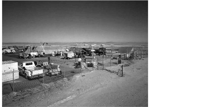
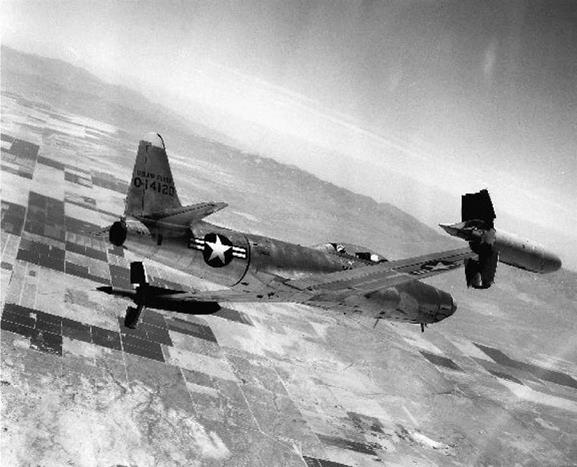
The analyses produced other concerns as well. Differential heating of the wing leading edge resulted in changes to the natural torsional frequency of the wing unless the design used some sort of flexible expansion joint. The hot leading edge expanded faster than the remaining structure, introducing a compression that destabilized the section as a whole and reduced its torsional stiffness. To negate these phenomena, researchers segmented and flexibly mounted the leading edge to reduce thermally induced buckling and bending. Similar techniques found use on the horizontal and vertical stabilizers.

COMFARISQN OF INCONEL X WITH OTHER ALLOYS

TENSILE YIELO STRESS*

К 51

DESIGN TEMR

Подпись: IOO MILITARY SUPPORT MILITARY SUPPORT MILITARY SUPPORT

BTU/SQ FT/SEC

Langley evaluated many materials for the proposed hypersonic research airplane, but the availability of Inconel X and its exceptional strength at extremely high temperatures, made it,

almost by default, the preferred material for a hot-structure design. Coincidently, the researchers at NACA Langley discovered that the skin thickness needed to withstand aerodynamic stress was about the same as the amount of structure needed to absorb the thermal load from the high – altitude mission. (NASA)

Perhaps more worrisome was the question of potential propulsion systems. The most promising configuration was found to be four General Electric A1 or A3 rocket engines, due primarily to the "thrust stepping" this configuration provided.-1110! At the time, rocket engines could not be throttled (even today, most rocket engines cannot be). Several different techniques can be used to throttle a rocket engine, and each takes its toll in mechanical complexity and reliability. However, a crude method of throttling did not actually involve changing the output of the engine, but rather igniting or extinguishing various numbers of small engines. For instance, in a cluster of three 5,000-lbf engines, the available thrust levels (or "steps") would be 5,000, 10,000, and 15,000 lbf. Since most rocket engines were not restartable (again, the concept adds considerable mechanical complexity to the engine), once an engine was extinguished it could not be restarted. Thrust stepping or throttling allowed a much more refined flight profile, and largely defined the propulsion concept for the eventual X-15.-1111-

At this stage of the study, the vehicle concept itself was "little more than an object of about the right general proportions and the correct propulsive characteristics" to achieve hypersonic flight. However, in developing the general requirements, the Langley group envisioned a conceptual research aircraft that would serve as a model for the eventual X-15. The vehicle they conceived was "not proposed as a prototype of any of the particular concepts in vogue in 1954…[but] rather as a general tool for manned hypersonic flight research, able to penetrate the new regime briefly, safely, and without the burdens, restrictions, and delays imposed by operational requirements other than research." 112

Although the Becker group was making excellent progress, their continued investigation of the "space leap" caused considerable controversy. The study called for two distinct research profiles. The first-the basic hypersonic research flights—consisted of a variety of constant angle-of-attack, constant-altitude flights to investigate aero-thermodynamic characteristics. However, the second flight profile explored the problems of future space flight, including investigations into "high-lift and low-L/D [lift over drag] during the reentry pull-up maneuver." Researchers recognized that this was one of the principal problems for manned space flight from both a heating and piloting perspective.-113!

This brought yet more concerns: "As the speed increases, an increasingly large portion of the aircraft’s weight is borne by centrifugal force until, at satellite velocity, no aerodynamic lift is needed and the aircraft may be operated completely out of the atmosphere. At these speeds the pilot must be able to function for long periods in a weightless condition, which is of considerable concern from the aeromedical standpoint." By employing a high-altitude ballistic trajectory to roughly 250,000 feet, the Becker group expected that the pilot would operate in an essentially weightless condition for approximately 2 minutes. Attitude control was another problem since traditional aerodynamic control surfaces would be useless at very high altitudes. To solve this problem, the group proposed using small hydrogen-peroxide thrusters for attitude control outside the sensible atmosphere.

While the hypersonic research aspect of the Langley proposal enjoyed virtually unanimous support, it is interesting to note that in 1954 most researchers viewed the space-flight aspect with, at best, cautious tolerance. There were few who believed that any space flight was imminent, and most believed that manned space flight in particular would not be achieved until many decades in the future, probably not until the 21st century. For instance, John Becker remembers that even the usually far-sighted John Stack was "not really interested in the reentry problem or in space flight in general." Several researchers opined that the space-flight research was premature and recommended it be eliminated. Fortunately, it remained.114-

Langley’s work throughout 1954 demonstrated one thing: the need for flexibility. Since their inceptions, the Brown and Becker groups had run into one technical problem after another in the pursuit of a conceptual hypersonic aircraft capable of making a space leap. Conventional wisdom had provided experimental and theoretical guidance for the preliminary design of the configuration, but had fallen far short of giving final answers. Contemporary transonic and supersonic aircraft designs dictated that the horizontal stabilizer should be located far above or well below the wing plane, for example, but that was wrong. Ballistics experts committed to pointy-nosed missiles had continued to doubt the worth of Allen’s blunt-body concept, but they too were wrong. Conversely, the instincts of Floyd Thompson, who knew very little about hypersonics but was a 30-year veteran of the vicissitudes of aeronautical research, had been sound. The design and research requirements of a hypersonic vehicle that could possibly fly into space were so radically new and different, Thompson suggested, that only "fresh approaches" could meet them. He was correct.