Category X-15 EXTENDING THE FRONTIERS OF FLIGHT

RETROSPECT

After the first 50 flights with the XLR99 engine, researchers at the FRC took a step back and reflected on the problems they had experienced. Excepting the single incident on the ground that gave Scott Crossfield his wild ride at the Rocket Engine Test Facility, the engine had proved to be remarkably safe during operation. Although there had been a multitude of problems, large and small, the program described itself as "engine safe."1981

One of the major factors in successful engine operation in the X-15 after launch was the amount of checkout the engine went through on the ground beforehand. This had its drawbacks, however, since "operating cycles on the hardware for ground assurance checks take a relatively large portion of the hardware life," according to C. Wayne Ottinger and James F. Maher. Illustrating this is the fact that 350 ground runs, including 100 with the XLR99 installed in the X-15, had been necessary to achieve the first 50 flights. For the first dozen flights, the FRC conducted a test of the engine installed in the X-15 before each mission. After the 12th flight, a flight attempt could follow a successful flight without a test firing-a process that saved 18 ground runs during the next 38 missions.1991

Between the conclusion of the PFRT and May 1963, 90 modifications were made to the engine configuration. In order to meet the safety criteria imposed by the Air Force, Reaction Motors used the "single-malfunction" concept, i. e., it designed the engine so that no single malfunction would result in a hazardous condition. The company used a dual-malfunction concept with regard to structural failure, meaning that if one member failed, another would carry its load. The PFRT series of tests convincingly demonstrated these capabilities, since 47 different malfunctions resulted in a safe shutdown.11001

Despite all of the effort that went into developing a restartable engine, this capability was not used during the first 50 flights, except for four flights on which it was used to start an engine that had failed on the first attempt. However, another feature proved to be a welcome addition: the ability to operate the pump and both igniter stages while the research airplane was attached

to the carrier aircraft. This allowed verification of over 90% of the moving components in the engine before the research airplane was dropped.-1401

When the engines first arrived at Edwards, several components (particularly leaking pumps and malfunctioning hydrogen-peroxide metering valves) accounted for an abnormally high percentage of the flight delays. Relaxing the operating requirements regarding certain pump leaks and limiting the duration of the pump run time did as much to reduce pump delays as did the ultimate fixes themselves. NASA also noted that "excessive time lag in obtaining approval for correction" and "excessive time required to develop the correction and complete flight hardware incorporation of fixes after approval" were significant contributors to the delays caused by the XLR99.[102]

The control box was the heart of the engine and was responsible for the control and sequencing of the engine. This was not a computer by the modern definition of the term, but rather a mechanical sequencer with some electronic components. The major problem experienced by this device during the first 50 flights was the failure of pressure switches due to ammonia corrosion of the silver contacts-echoes of the original warnings on the effects of ammonia exposure. Reaction Motors finally eliminated this problem by switching to gold contacts. In addition, there were random wiring discrepancies, servo amplifier failures, and timer failures.-103

RETROSPECT

During the latter part of 1962, several in-flight oxidizer depletion shutdowns resulted in second – stage igniter damage because reduced liquid-oxygen injector pressure allowed the reverse flow of ammonia into the oxidizer inlet. The subsequent minor explosion either bulged the igniter inlet manifold or blew the face off the second-stage igniter. Reaction Motors installed an auxiliary purge system to correct the problem. In addition, several sensing-line detonations had defied correction throughout the summer of 1963. These occurred in the second-stage chamber sense line during any thrust decrease when unburned combustible gas from the previous increasing pressure cycle entered the sense line. Interestingly, engineers initially attributed this problem to a lubricant used in the main propellant valve. They believed that the "liquid-oxygen safe" lubricant was impact-sensitive and responsible for the second-stage igniter explosions. Although further investigation later proved this theory incorrect, analysis of the lubricant revealed that some batches were out of specification on impact sensitivity.-1104!

The hydrogen-peroxide system that powered the turbopump experienced several problems, including erratic metering valve operation, catalyst-bed deterioration, seal failures, and corrosion. Engineers corrected the metering valve problem by increasing the clearance around the valve. The substitution of electrolytically produced hydrogen peroxide for organically produced product solved the catalyst-bed deterioration, although it technically violated the engine qualification since the PFRT had been run with electrolytically produced hydrogen peroxide. The development of improved gaskets and seals relieved the seal failures and solved most of the corrosion problems. The turbopump itself suffered only minor problems, mainly steam and propellant leaks. The lowering of specifications governing the allowable leakage rate provided the most progress in working with the problem.-105

The oxidizer system also created some headaches, even though it was largely a copy of the original XLR30 system. The major problems were propellant valve leakage and the need for a quick-change orifice. Improved lip and shaft seals initially helped control the leakage, and eventually Reaction Motors introduced a redesigned valve that eliminated the problem. Prior to the incorporation of the quick-change orifice, it was necessary to remove the engine from the aircraft in order to change the oxidizer-to-fuel ratio. Engineers changed the ratio based on the proposed altitude for the next flight to maximize the performance of the engine. Once Reaction Motors incorporated the quick-change modification, engineers at Edwards could insert different-sized probes into the orifice while the engine was in the aircraft. This eliminated the need to conduct a ground run after reinstalling the engine. Tailoring the oxidizer-to-fuel ratio actually allowed the engine to produce slightly over 61,000 lbf at some altitudes.-105

Although nearly everybody considered the XLR99 a good research airplane engine, the engine was far from perfect. Milt Thompson observed that "the LR99 was amazingly reliable if we got it lit, and if we did not move the throttle while it was running." Joe Vensel, the director of FRC flight operations echoed the advice: "[I]f you get the engine lit, leave it alone, don’t screw with it." This is perhaps overstating the case, but not by much. During the early part of the flight program, the XLR99 had a remarkably poor record of starting when the pilot wanted. Part of the problem was that the early flight rules said to start the engine at minimum throttle (50% for the very early engines, and 30% for the later ones). The engine simply did not like to start at those throttle settings. After the program decided to start the engine at 100% throttle, things got much better.107-

Still, even after the engine lit, it did not particularly like to throttle. As a result, Joe Vensel directed the pilots not to throttle the engine until after the X-15 had sufficient energy to make it back to Edwards. Milt Thompson talked him into changing his mind for one flight (3-29-48) in order to accommodate a research request, and Thompson ended up on Cuddeback Lake when the engine quit as he throttled back 42 seconds after launch. After that, the restriction was rigorously enforced: no throttle movement until the airplane could glide back to Edwards. Although the lower throttle limit on later engines was 30%, the program decided not to go below 40% because of the persistent vibration problem. The pilots also learned to move the throttle slowly to minimize the chances of the engine quitting. It mostly worked, and flight planner Bob Hoey does not remember any significant problems occurring later in the program.-1108!

During the flight program, eight in-flight propulsion problems resulted in emergency landings. These included one due to no ignition, one because the engine hung at 35% thrust, one shutdown when the throttle was retarded, two due to low fuel-line pressures, one turbopump-case failure, one ruptured fuel tank, and one due to a perceived lack of fuel flow from the external tanks on X – 15A-2. Overall, it was not a bad record for a state-of-the-art engine over the course of 199 flights.

Although 11 flight engines were manufactured, only eight were available to the flight program. One (s/n 105) was lost in the ground explosion that seriously damaged the X-15-3 before the XLR99 had even flown, and two other flight engines were dedicated to the ground-test program. Making 199 flights on eight engines was an outstanding achievement.

XLR99 Flight Engine Run Time Summary (Minutes per Year)

Year

s/n 103

s/n 104

s/n 106

s/n 107

s/n 108

s/n 109

s/n 110

s/n 111

No. of flights

Pre Del

13.47

31.23

7.90

8.63

6.29

4.64

4.45

4.43

1960

11.42

5.88

0

0

0

0

0

0

3

1961

16.66

0

12.05

4.78

13.34

5.98

1.53

5.75

13

1962

8.72

6.13

7.02

18.32

5.77

9.45

11.75

11.87

30

1963

1.43

8.52

0

16.27

5.58

2.55

(9.10)*

11.22

6.32

21

1964

12.03

11.05

6.08

6.52

7.68

6.58

0

(6.33)*

3.24

(20.03)*

27

1965

12.03

7.86

3.26

14.22

15.10

7.73

8.40

5.93

32

1966

2.72

0

15.07

9.98

0.52

2.37

8.85

4.65

20

1967

11.45

3.98

1.23

2.63

5.50

2.72

4.72

2.30

15

1968

3.80

3.60

2.60

0.70

3.63

3.25

1.22

Lost+

8

Total

73.73

78.25

55.21

82.05

63.41

45.77

(54.87)*

52.14

(58.49)*

44.49

(64.52)

169

*Additional time used for ground testing of second-stage igniter purge modification.

+ Lost in X-15-3.

Data courtesy of Robert G. Hoey.

As was done for most components on the X-15, all XLR99 maintenance was performed at Edwards using a local, depot-level maintenance approach. With few exceptions, the engines ran for a brief period in the PSTS before NASA installed them in one of the X-15s or stored them for future use. Since the X-15 maintenance philosophy was to provide sufficient spare engines and maintenance personnel to ensure 100% flight engine availability, it was normal to have a backlog of engines in flight-ready storage (essentially spares). The engine activity was divided into three categories: 1) installed in an X-15, 2) active maintenance, and 3) flight-ready storage. Early in the program, NASA conducted one or more ground engine runs (leak checks) after installing the engine in the airplane and before every flight. This requirement for an aircraft engine run between flights was relaxed later in the program, assuming there were no engine problems on the previous flight.1102*

RETROSPECT

Milton O. Thompson had more than his fair share of experience with the XLR99, and enjoyed sharing it during discussions with various groups after the X-15 program ended. One of his favorite stories concerned the emergency landing he had to make on Flight 3-29-48 when the XLR99 quit as he throttled back 42 seconds after launch. (NASA)

The staff of the AFFTC Rocket Engine Maintenance Shop from 1961 to 1968 in support of the XLR99 averaged about 37 people. Interestingly, in 1965 these technicians made about $4 per hour on average. This shop was responsible for all maintenance of all uninstalled XLR99s; the FRC handled minor repairs of installed engines. Every 30 operating minutes, on a test stand or in the airplane, each XLR99 had to undergo a "30-minute" inspection that took just over two weeks to complete. The Air Force overhauled the engines when needed, a process that took just over a month. Recoating the thrust chamber, done by the FRC, took a few days.-1110

Unlike many rocket engines of that era, the XLR99 was equipped with a malfunction-detection and automatic-shutdown system. For most engines, reliability is based on the number of start attempts. However, since one of the primary features of the XLR99 was its ability to restart in flight, its total reliability was defined as the number of successful engine operations per flight attempt, regardless of the number of start attempts. The resulting X-15 data and point estimates of reliability were as follows:[111

XLR99/X-15 flight attempts^112 169 Successful engine operations 165 Successful first-start attempts 159 Overall reliability 97.6%

First-start reliability 94.0%

Over the course of the X-15 program, the flight engines accrued a total of 550.53 minutes of run time, plus an undetermined amount on ground-test engines. A total of 1,016 engine starts were recorded for the flyable engines (dedicated ground-test engines incurred many more). Although there were numerous automatic shutdowns, there were no catastrophic engine failures. The safety of the XLR-99 engine (defined as the probability of non-catastrophic engine operation) may be conservatively estimated by dividing the number of successful starts (1,016) by the number of starts plus one (1,017) (assuming the next start to be catastrophic for the worst case). The resulting estimate of the probability of non-catastrophic engine operation is approximately

0.99902ДШ

In retrospect, the engine still casts a favorable impression. The XLR99 pushed the state of the art further than any engine of its era, yet there were no catastrophic engine failures in flight or on the ground. There were, however, many minor design and manufacturing deficiencies, particularly with the Rokide coating on the thrust chamber. Surprisingly, the primary source of problems on most large rocket engines-the turbopump-proved to be remarkably robust and trouble free.

A Replacement

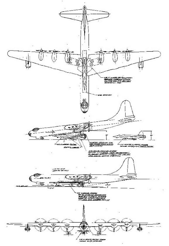
In early 1957, just as North American was preparing to begin modifications on the B-36, the X – 15 Joint Operations Committee began considering replacements for the B-36 for various reasons. There were some concerns that the research airplane would not be as stable as desired during launch because of the relatively slow speed of the B-36. Another reason was that as the weight of the X-15 and its subsystems grew, the Air Force and NACA began to look for ways to recover some of the lost performance; a faster carrier would compensate somewhat for the increased X – 15 weight. Perhaps most vocally, personnel at Edwards believed that the 10-engine B-36 would quickly become a maintenance nightmare since the Air Force was already phasing it out of the inventory. A lack of spare parts and depot maintenance capabilities for the B-29 and B-50 carrier aircraft had already delayed the X-1 and X-2 programs on several occasions.1871

A survey by North American identified the Boeing B-52 Stratofortress, Convair B-58 Hustler, and

Boeing KC-135 Stratotanker as possible B-36 replacements. It is interesting to note that Douglas had apparently chosen the B-52 for their model 671 study four years earlier.-88

The supersonic B-58 was attractive from a performance perspective, but looked less attractive from the maintenance and availability standpoint. Nevertheless, on 22 January 1957, future X-15 pilot Neil Armstrong traveled to the Convair plant in Fort Worth to discuss the possibility of using a B-58 to launch the research airplane. The first problem was that the 22-foot wingspan and 18- foot tail-span of the X-15 both intersected the plane of the rearward-retracting main gear on the B-58. This would have necessitated moving the entire X-15 forward of the desired location. Convair engineers believed that this might be possible, but it would require designing a new nose gear for the B-58 since the X-15 would block the normal nose gear. Another possibility was to beef up the X-15 nose gear and use it while the pair was on the ground. The inboard engine nacelles on the B-58 would likely need to be "toed" outward or simply moved further out on the wing, and either would have necessitated major structural changes. Engineers would need to design a way to fold the X-15 vertical stabilizer because they could not make room for it within the B-58 fuselage without severing a main wing spar. The design of the B-58 included a weapons/fuel pod that weighed 30,000 pounds, only slightly less than the X-15. However, the baseline mission included using the fuel in the pod prior to dropping the pod, and the maximum drop weight was only 16,000 pounds. This would necessitate a new series of tests to validate that a heavier object would separate cleanly, especially at supersonic speeds. However unfortunately, the B-58 was obviously not going to work.-89

The landing-gear configuration on the KC-135 and B-52 precluded carrying the X-15 under the fuselage, as had been the practice in all earlier research programs. Although the performance and availability of the KC-135 made it attractive, nobody could figure out where to carry the research airplane since the Stratotanker had a low-mounted wing and relatively short landing gear. Engineers quickly dropped the KC-135 from consideration.-1901

The B-52 also offered an excellent performance increment over the B-36, and since the Boeing bomber was still in production, the availability of spare parts and support should not become an issue. There was a large space on the wing between the fuselage and inboard engine nacelle that could be adapted to carry a pylon, and investigations were already under way to install similar pylons on later B-52s to carry air-to-surface missiles. In May 1957, NASA directed North American to perform an initial feasibility study on using the B-52 as an X-15 carrier. The study lasted several weeks and the results were favorable. At a meeting on 18-19 June 1957, the program officially adopted the B-52 as a carrier aircraft. Representatives from the FRC discussed concerns about maintenance and availability issues, and NASA recommended procuring two carrier aircraft to ensure that the flight program would proceed smoothly. The Air Force subsequently authorized North American to modify two B-52s in lieu of the single B-36.-91

The North American investigations showed that the X-15, as designed, would fit under the wing between the fuselage and inboard engine pylon at an 18% semi-span location. The wing structure in this location was capable of supporting up to 50,000 pounds, so the 31,275-pound research airplane did not represent a problem. Nevertheless, this was not the ideal solution. The X-15 pilot would have to be in the research airplane prior to takeoff, and the large weight transition when the B-52 released the X-15 would present some interesting control challenges.-921

Lawrence P. Greene, the North American chief aerodynamicist wrote, "One item which caused considerable concern in the early evaluation was the fact that in this installation, the pilot could not enter the airplane in flight as had been possible in the B-36. This limitation was of concern from both the fatigue and safety aspects; however, the time from take-off of the B-52 to launching the X-15 is about 1.5 hours, and considerable effort has been expended in plans for making the pilot comfortable during this time. In the event of an emergency, the configuration permits the pilot to eject safely while the X-15 and B-52 are still connected.’4931

Further analysis and wind-tunnel tests indicated that the potential problems were solvable, and that the increase in speed and altitude capabilities was desirable. Researchers conducted additional wind-tunnel tests of a 1/40-scale model in the Langley 7 by 10-foot tunnel and the University of Washington wind tunnel to explore possible flutter problems, but did not discover any critical issues. Researchers installed six-component strain-gage balances in both the B-52 and X-15 models, and the B-52 model had additional strain gages and a pressure gage located in the horizontal stabilizer to obtain measurements of possible tail buffet created by the X-15 installation.-1941

Initially the X-15 was to be carried under the left wing of the B-52. It was moved to the right wing to "permit easier servicing of the X-15 when installed on the B-52," although exactly what was easier to service was not described. Researchers had conducted most of the wind-tunnel tests with models of the X-15 under the left wing. However, since both aircraft were largely symmetrical, researchers decided that the test results were equally as valid for the right-wing configuration. The initial design also had an anti-buffet fairing that partially shielded the pylon from the airflow, but wind-tunnel tests showed that the fairing did not significantly help anything, and the engineers subsequently deleted it.1951

Originally, the Air Force indicated that it could make the two prototype B-52s (the XB-52 and YB – 52) available to the X-15 program. Personnel at Edwards feared that the use of these two non­standard aircraft would result in the same maintenance and parts availability problems they were attempting to avoid. By August 1957 the Strategic Air Command agreed to make an early- production B-52A available, and the Air Force subsequently assigned serial number 52-003 to the program in October 1957. In May 1958 the Air Force also assigned an early RB-52B (52-008) to the X-15 program. Both aircraft had been involved in isolating problems with the B-52 defensive fire control system, and Boeing delivered each aircraft to North American after the completion of their test programs.-1961

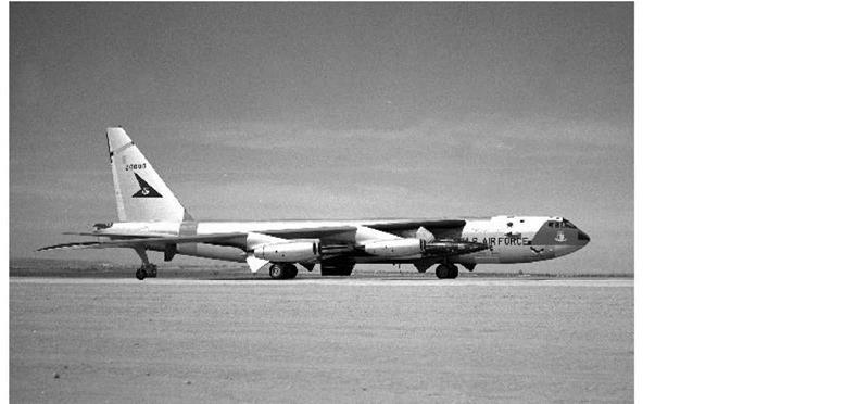
On 29 November 1957 the B-52A arrived at Air Force Plant 42 in Palmdale, California, after a flight from the Boeing plant in Seattle. North American placed the aircraft into storage pending modifications. On 4 February 1958, technicians moved the aircraft to the North American hangar and began modifying it to support the X-15 program. The aircraft, now designated NB-52A, flew to Edwards on 14 November 1958 and was subsequently named "The High and Mighty One." The RB-52B arrived in Palmdale for similar modifications on 5 January 1959, and, as an NB-52B, flew to Edwards on 8 June 1959; the airplane briefly wore the name "The Challenger.’4271

A Replacement

The Air Force initially contributed the third production B-52A (serial number 52-003) to the X-15 program. This airplane had been used in initial B-52 testing at Boeing in Seattle, and came to Edwards when its testing duties were completed. The airplane was modified by North American to support carrying and launching the X-15. The aircraft, now designated NB-52A, flew to Edwards on 14 November 1958 and was subsequently named The High and Mighty One. (NASA)

The major modifications to the two NB-52s included the following:^981

1. The no. 3 right main wing fuel cell was removed to allow the installation of pylon tie fittings and supports in the front and rear wing spars.

2. The inboard flap mechanism on both wings was disconnected, and the flaps were bolted to the flap tracks. A cutout through the right inboard flap provided clearance for the X-15 vertical stabilizer.

3. A pylon was installed between the right inboard engine nacelle and the fuselage. The pylon contained a primary hydraulic and a secondary, pneumatic-release mechanism for the research airplane.

4. Changes to the NB-52 avionics included the addition of an AN/APN-81 Doppler radar system to provide ground-speed and drift-angle information to the stable platform in the X-15, an auxiliary UHF communications system to provide additional communications channels, and a change in the AN/AIC-10 interphone system to provide an AUX UHF position.

5. The fuselage static ports were removed from the right side of the NB-52 to allow installation of the forward television camera. The airspeed system was recalibrated to use only the left static ports. This worked surprisingly well, even during sideslip maneuvers, with "no measurable difference" noted.

6. Two television cameras were installed in streamline fairings on the right side of the NB-52. The rear camera pointed generally forward and was equipped with the zoom lens to allow the launch operator to focus on areas of interest on the rear of the X-15. The forward camera used a fixed-length lens pointed outward and slightly rearward to allow a view of the X-15 forward fuselage. Two monitors were located at the launch operator position, and either could show the view from either camera. Four floodlights and three 16-mm motion picture

cameras were also installed. Two of these were Millikan DBM-5 high-speed units located in a window on the right side of the fuselage at station 374 and in an astrodome at station 1217. The third was an Urban GSAP gun camera mounted in the pylon pointed downward to show X-15 separation.

7. The NB-52 forward-body fuel cell was removed to provide space for inspecting and maintaining various fluid and gas lines installed in the wing. The mid-body fuel cell was removed and the fuselage area above the bomb bay was reworked to provide space for 15 nitrogen and nine helium storage cylinders. Early during the flight program, a separate liquid-nitrogen supply was added to the pylon to cool the stable platform on the X-15.

8. Two stainless-steel liquid-oxygen tanks (a 1,000-gallon "climb" tank and a 500-gallon "cruise" tank) were installed in the bomb bay. The tanks were not jettisonable, although the contents could be vented through a streamlined jettison line protruding from the forward left side of the bomb bay. Liquid oxygen would be sucked into the right rear landing gear well if the doors were opened while liquids were being jettisoned; this was procedurally restricted.

9. A launch operator station replaced the normal eCm compartment located on the upper rear flight deck. After the first flew flights with X-15-1, an astrodome-type viewing window was added to the NB-52 above the forward television camera in case the video system failed, and a duplicate set of controls for the liquid-oxygen top-off system were located above the window to allow the launch operator to top off the X-15 while looking out the window. A defrosting system was provided for the window, and two steel straps across the window provided safety for the launch operator in case the window blew out.

10. Changes to the NB-52 flight deck included the addition of a master launch panel on the lower left side of the main instrument panel, launch-indicating lights in the pilot’s direct field of vision, a normal launch switch on the left console, and an emergency launch handle below and to the left of the master launch panel. Changes were also made to the B-52 fuel control panel in both aircraft to reflect the removal of the fuel cells and eliminate the external tank position.

11. Breathing oxygen was made available to the NB-52 crewmembers at all times. In addition, oxygen was tapped from the NB-52 oxygen system to supply the X-15 research pilot with breathing oxygen until flight release.

12. A high-speed wheel, tire, and braking system was installed on the NB-52 because the original landing gear was only rated to 174 knots. The new system incorporated an adequate margin for no-flap takeoffs and landings at heavy weights, and was rated to 218 knots.

13. All military systems, including the tail turret and defensive fire-control system, were removed. The modifications to the rear fuselage to delete the tail turret differed between the two aircraft. The ability to carry the reconnaissance pod on the RB-52B was also deleted.

14. Later in the flight program, additional instrumentation was added to the launch operator position to allow monitoring of the MH-96 adaptive flight control system and X-20 inertial flight data system. A "stable platform control and monitoring unit" was also added to the NB-52B to allow the launch operator to monitor and control the stable platform during captive-carries of the pod-mounted system used for post-maintenance validation.

These changes differed somewhat from those initially proposed for the NB-52. For instance, the original design had a pressurized compartment in the bomb bay for an observer. When North American deleted this from the design, engineers moved the liquid-oxygen top-off tank there instead. The launch operator position was moved from the left side of the aircraft to the right side to permit "continuous observation of the research vehicle" after the X-15 itself was moved to the right side. This also allowed the launch operator to remain in his ejection seat for the entire launch process (previously he had to stand up occasionally to visually check the X-15).[99]

The change from a B-36 to a B-52 did not come cheaply. Although the basic aircraft was provided

at no charge to the program, North American submitted a bill for an additional $2,130,929.06 for the modification of the first B-52. The second airplane cost somewhat less since it did not require wind-tunnel testing and the basic engineering was already complete.

The Air Force named Captain Edward C. Gahl as the project pilot for the NB-52 carrier aircraft in 1957. Gahl was well up to the task. He was a graduate of the Experimental Test Pilot School and had been involved in flight-testing the B-52 and KC-135 prior to joining the carrier program. Unfortunately, Gahl perished in a mid-air collision on 16 June 1958, long before the NB-52A had completed its modifications. Captain Charles C. Bock, Jr., replaced him as the chief carrier pilot.™

After the modifications to the NB-52A were completed, engineers from the Air Force, Boeing, NASA, and North American conducted a ground vibration test on the pylon using the X-15-1. The tests built on data already accumulated by Boeing-Wichita while the B-52F was being integrated with the North American GAM-77 Hound Dog missile.-11011 Technicians constructed a structural steel frame to make the NB-52 wing as rigid as possible, effectively preventing any movement by the NB-52 wing, pylon, horizontal stabilizer, or fuselage. The X-15 was excited by electromagnetic shakers and sensors mounted on the X-15 fuselage, wing, horizontal stabilizer, and vertical stabilizers measured the amplitude of motion for various frequencies. Researchers used these data to determine the natural vibration frequencies of the pylon to verify data obtained from a series of flutter model tests of the NB-52/X-15 combination conducted by Boeing in a low-speed wind tunnel. The results from these two tests demonstrated that the flutter speed of the NB-52 when carrying the X-15 was well above the required launch conditions.-11021

However, there was some concern about the jet exhaust from engine nos. 5 and 6 of the NB-52 impinging on the X-15 empennage. Specifically, the engineers worried that the engine acoustics would detrimentally affect the X-15’s structural fatigue life. To mitigate this concern, at least initially, the engineers decided the NB-52 pilots would restrict engine nos. 5 and 6 to 50% thrust while carrying the X-15. The engineers and pilots believed this was an acceptable compromise between protecting the X-15 and the need to provide adequate power and control of the NB-52 during takeoff. At 50% power on these two engines, the tip of the X-15 horizontal stabilizer was exposed to 158 decibels and the sides of the vertical stabilizers were exposed to 144 decibels; at 100% power each value was about 10 decibels greater.-103

Although it appeared feasible to operate the carrier aircraft engines at reduced power, it was not desirable, so North American began redesigning some parts of the X-15 to increase their fatigue life. The modifications to the vertical stabilizers consisted of increasing the rivet diameter, using dimpled-skin construction instead of countersunk rivets, and increasing the gage of the corrugated ribs along the edge where they flanged over to attach to the cap strip. The horizontal stabilizer used larger rivets and dimpled construction.104

To verify the effectiveness of the modifications, researchers conducted several acoustic tests to establish the structural fatigue life of both the original and modified aft X-15 structures. A static ground test was run on a simulated X-15 empennage to determine the sound levels beneath the pylon (the hastily-constructed structure could not be attached to the pylon) with the B-52 engines operating at 85% rpm (equivalent to 50% thrust). Both the original and modified test panels withstood 20 hours of operation with no failure. Subsequent analysis indicated that the original panels would be adequate for operation at 50% power, and the new panels would allow operation at 100% power. North American decided to retrofit all three X-15s with the new structure, which would take several months.-103

Following completion of these tests, Captain Bock and Captain John E. "Jack" Allavie tested the NB-52A along with launch panel operator, William "Bill" Berkowitz from North American. To eliminate possible interference with the X-15, the engineers decided to bolt the inboard flaps in the closed position, meaning that the NB-52 pilots would have to fly the airplane without flaps. Therefore, the pilots dedicated the initial flights to developing techniques for no-flap operations and measuring various performance parameters of the modified NB-52. The takeoffs were conducted using 50% power on engine nos. 5 and 6 since it appeared that initial flights would be restricted to this power setting until all three X-15s were modified. The NB-52 also accomplished qualitative stability tests over the speed and altitude ranges anticipated for the X-15 program.-11061

There was very little no-flap, takeoff-and-landing experience with the B-52 available to draw on, so Bock and Allavie conducted the initial tests using predicted information and recommendations from Boeing personnel. Engineers based the anticipated takeoff speeds and distances on a lift coefficient of 0.75, meaning that the NB-52 had to be rotated about the aft main gear to an attitude that would produce the correct amount of lift. This was contrary to normal B-52 takeoffs where all four main gear lift at the same time. The pilots also realized that the 10% chord elevator used on the B-52 would have limited authority and that the horizontal-stabilizer trim setting would be important if reasonable takeoff distances were to be attained.-1071

The flight tests involved a fair amount of trial and error. For instance, on the first test at a gross weight of 315,000 pounds (the maximum predicted weight for an actual X-15 flight), Bock set the stabilizer trim 0.5 degrees more than the normal recommended trim of 0 degrees. The pilots ran engine nos. 5 and 6 at 50% power, and fuel loading simulated the weight (but not the drag) of the X-15 on the right wing. The predicted takeoff distance was 10,500 feet at a speed of 176 knots. However, the NB-52 would not rotate, even with the control columns pulled all the way back.

After the airplane passed the 10,000-foot marker on the runway, the pilots went to full power on engine nos. 5 and 6, and the aircraft broke ground at 12,650 feet at 195 knots. Engineers later calculated the actual lift coefficient for this takeoff at 0.639. During a normal B-52 takeoff with the flaps down, all four main gear leave the ground simultaneously and the lift coefficient is approximately 0.55.1081

Subsequent takeoff tests established that a trim setting of 2 degrees nose up was the optimum setting (this represented one-half of the available trim). This setting produced reasonable takeoff distances and a rapid but controllable rotation just prior to liftoff, with the pilot holding the column all the way back. The maximum lift coefficients were later determined to be approximately

0.71.11091

Landings also proved challenging. Again, the airplane needed higher than normal lift coefficients during landing in order to produce reasonable touchdown speeds and landing distances. Unlike the traditional B-52 landing on all four main gear at once, the NB-52s landed on their two aft main gear. The problem was that the designers had not intended the B-52 to do this. Very little control could be achieved as the aircraft rotated to a level attitude, and the forward main gear usually hit with a noticeable impact. Accelerometers installed in the pylon after the initial landing tests measured impact loads of 1.5-1.8 g. The engineers considered these annoying but acceptable.-11101

After the front main gear touched down, the pilots fully extended the NB-52 air brakes and the drag chute deployed at 140 knots. When landing at heavier weights, such as when returning with the X-15 still attached, the pilots used moderate braking. When these techniques were used with a 300,000-pound airplane, the touchdown speed was 172 knots and the landing roll took 10,800 feet. At 250,000 pounds, touchdown occurred at 154 knots and light braking used only 9,300

feet of runway. The importance of the drag chute was telling: one landing at 267,000 pounds with a failed drag chute required over 12,000 feet to stop even with heavy braking, and resulted in one brake being severely warped, necessitating its replacement.111

The NB-52 pilots now felt confident that they could control their airplane with the X-15 attached, so the first captive flight was attempted. The right wing sat on its outrigger wheel during the initial takeoff roll in order to keep spoiler extension and the associated drag at a minimum. The engineers did not expect the additional drag of the X-15 to result in any serious degradation of low-speed performance; however, there existed some concerns about the possible impingement of the X-15 wake on the right horizontal stabilizer of the NB-52.1121

Despite the concerns about exhaust impingement from engine nos. 5 and 6, the X-15 program had not taken a firm stand on what power levels to use. Bock and Allavie therefore decided to use full power on all eight engines for the flight on 10 March 1959. The takeoff gross weight was 258,000 pounds and the center of gravity was located at 26.5% mean aerodynamic chord (MAC). The actual takeoff distance was 6,085 feet and liftoff occurred at 172 knots. The lift coefficient developed on this takeoff was 0.66 since the pilots did not attempt to achieve maximum performance. Bock just wanted to demonstrate that the mated pair would actually fly as predicted, which it did for 1 hour and 8 minutes. The second flight (which was supposed to result in an X – 15 glide flight, but did not due to a radio failure) produced largely similar results. On the third flight (another unsuccessful attempt at a glide flight) engine nos. 5 and 6 were set to 50% thrust until an indicated airspeed of 130 knots was reached, and then they were advanced to full power. This procedure extended the takeoff distance to 7,100 feet at the same gross weight and similar atmospheric conditions.-1113!

Following takeoff, engine nos. 5 and 6 were set to 50% thrust at 5,000 feet altitude and the mated pair continued to climb using a circular pattern around Rogers Dry Lake. This kept Scott Crossfield in the X-15 within gliding distance of a suitable lake in the event of a possible emergency jettison. The NB-52 pilots flew all of these early tests to an altitude of 45,000 feet and Mach 0.85, which was pretty much the maximum performance of the mated pair. Bock and Allavie flew simulated launch patterns and practiced emergency and aborted launch procedures, and Crossfield accomplished X-15 propellant jettison tests using a water-alcohol mixture that included red dye. Before each flight, technicians covered the underside of the right horizontal stabilizer of the NB-52 with a powdery substance so that the impingement would be easy to identify.-1141

Since the X-15 horizontal and vertical stabilizers used for these initial carry flights were the original design, the engineers decided to inspect them after the third flight. The inspection revealed several structural failures in the upper vertical stabilizer. For the most part, the corrugated ribs had failed where they flanged over to attach to the cap strip, but the most extensive failure was an 18-inch separation of the rib from the flange on the side away from the NB-52 engines. Subsequent investigation showed that the failures were largely a result of a previously unsuspected source: the turbulent airflow created by the X-15 pylon and the B-52 wing cutout. Researchers made pressure measurements to determine the exact environment around the wing cutout. Fortunately, the subsequent analysis indicated an acceptable fatigue life for the modified X-15 structures, even though the engineers had not factored this particular environment into the design. After this round of tests and analysis was completed, the pilots made most subsequent takeoffs with all eight B-52 engines operating at 100% power.-1151

at Edwards during the summer were conducted in the early morning in any case, and if the takeoff roll was computed to be too long, one of the lakebeds could always be used (although this only happened once during actual flight operations). The NB-52B eliminated this particular deficiency. Unlike the A-model, the NB-52B was quipped with water injection for its engines. Bock and Allavie tested the NB-52B using water injection on just the outer four engines, and on all engines except nos. 5 and 6, with promising results. Bock noted that the use of water injection "appreciably increases take-off performance and is considered mandatory for take-off from the paved runway at a weight of 300,000 pounds when the ambient temperature exceeds 90 degrees Fahrenheit.’,[116]

Takeoffs were initially made using runway 04 at Edwards because that runway had several miles of lakebed overrun available. This allowed the pilots to fly a better pattern during climb-out, but more importantly, it avoided the use of heavy braking in case of an aborted takeoff. Engineers considered the use of maximum braking "undesirable" because of potential damage to the X-15 if one of the NB-52 tires failed. The other direction, runway 22, has a road at the end of it instead of lakebed.-1117!

Pilots found the lateral and directional control systems of the carrier aircraft capable of trimming out the unbalance of the NB-52/X-15 combination. Most of the pilots noted that lateral control became sensitive above Mach 0.8, but believed that launches were possible up to Mach 0.85 with no particular problems. The evaluations did not reveal any buffeting in level flight. It was possible to induce a minor airframe buffet in maneuvering flight at 1.6 g (80% of the pylon load limit), but only at speeds well below the normal operating range. It was discovered that the specific range deterioration of the NB-52 was about 7% with an empty pylon; with the X-15 attached, the specific range decreased by approximately 16%. Given that researchers never planned to launch the X-15 from a distance of more than 500 miles, and the B-52 was an intercontinental bomber, nobody considered this decrease in range significant. Nevertheless, a nonstop flight in May 1962 demonstrated that the pair could fly 1,625 miles from Edwards to Eglin AFB, Florida.118!

A Replacement

The Air Force also provided the second production RB-52B (the fifth B-model) to the X-15 program. The RB-52B (52-008) arrived in Palmdale for similar modifications on 5 January 1959, and as an NB-52B, flew to Edwards on 8 June 1959; the airplane briefly wore the name The Challenger. The NB-52B went on to a long career at the Flight Research Center before being retired in 2005. (U. S. Air Force)

The engineers and pilots predicted that launching the X-15 would result in an instantaneous rearward shift of the NB-52 center of gravity, coupled with a tendency for the carrier aircraft to roll to the left. The X-15 glide flight (i. e., with no fuel) was expected to result in a 4.5% shift in the center of gravity, while full-fuel flights would result in a 9% shift (which rose to about 12% on the later X-15A-2 flights). Engineers calculated that the rolling tendency and pitch-up were well within the capabilities of the NB-52 to counter, and in fact actual operations revealed no particular problems. Under "normal" conditions, the center of gravity actually shifted approximately 7% and required a 40-pound push force on the control column to compensate, but the resulting pulse usually dampened in one cycle.[119]

Some other minor problems were discovered during the NB-52 flight tests. For instance, the aft alternator cooling air duct on the right-wing leading edge and the air ducts on the right side of the NB-52 fuselage ingested hydrogen peroxide residue during pre-launch operation of the X-15 nose ballistic control system. Engineers did not consider the residue hazardous since it was composed primarily of water. Interestingly, while the X-15 was attached to the NB-52, operation of the X-15 ballistic control system had no noticeable effect on the bomber. Operation of the X – 15 aerodynamic flight control also had no appreciable effect on the NB-52; however, a slight airframe buffet was noted when the X-15 speed brakes were extended. A flap extension on the X-15 caused a small nose-down trim change, and extension of the X-15 main landing skids was not even apparent in the bomber. Initially, extension of the X-15 nose gear resulted in a "thump" that was felt and heard in the NB-52, but later changes to the X-15 extension mechanism eliminated the event.-1120

On the other side of the equation, the NB-52 had some effects on the X-15. For instance, the NB – 52 fuselage and wing created noticeable upwash and sidewash on the X-15. Because of the NB – 52 wing sweep, the right wing of the X-15 was nearer to the B-52 wing leading edge and, consequently, flow over the X-15 right wing was deflected downward more than over its left wing. This difference in effective angle of attack of the right and left wings resulted in a right rolling moment. There were also some concerns that the X-15 might strike the carrier aircraft during separation. Because there was only two feet of clearance between the X-15 dorsal stabilizer and the cutout in the NB-52 wing, the X-15 could potentially strike the cutout if the X-15 bank angle exceeded 20 degrees before the airplane dropped below the NB-52 fuselage level (about 2.5 feet vertically). It was decided that all X-15 controls should be in the neutral position when the airplane was dropped, allowing the automatic dampers to take care of correcting the attitude. The first few X-15 launches experimented with the settings needed for the dampers to do this, but Scott Crossfield soon developed a consistent set of settings.-121

Scott Crossfield unexpectedly demonstrated the effects of not using the dampers on the third flight (2-3-6) when the roll damper failed at launch. The X-15 rolling velocity increased rapidly to a peak value of 47 degrees per second and a peak bank angle of 40 degrees. The X-15 dorsal stabilizer dropped below the NB-52 wing cutout within 0.5 second, with the tail barely clearing the cutout. Crossfield finally managed to get the X-15’s wings level about 7 seconds after launch.121

A Replacement

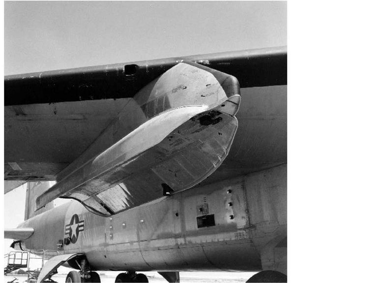
The most obvious modification was a large pylon under the right wing to carry the X-15. This was in contrast to all earlier X-planes, which had been carried partially submerged in the bomb bay of the carrier aircraft, something that was not possible given the B-52 configuration. The pylon worked satisfactorily and allowed the NB-52s to carry other research airplanes, such as the lifting bodies, later in their careers. (NASA)

The damper generally applied a left-aileron input of 6-8 degrees, reducing the peak right-roll velocity to about 25 degrees per second. The pilot could do the same if the damper failed. Aileron inputs of only 2 degrees, however, resulted in peak roll velocities in excess of 50 degrees per second, with corresponding bank angles of over 40 degrees. This risked a tail strike during launch. As the X-15 cleared the NB-52 flow field, it tended to roll left, so the damper and/or pilot had to be prepared to correct this sudden opposite movement. It took approximately 0.8 second for the X-15 to drop 10 feet below the NB-52.-1123

A Replacement

Another modification to the two NB-52s was a notch in the right wing to accommodate the X-15 vertical stabilizer. Because there was only 2 feet of clearance between the X-15 dorsal stabilizer and the cutout in the NB-52 wing, the X-15 could potentially strike the cutout if the X-15 bank angle exceeded 20 degrees before the airplane dropped below the NB-52 fuselage level (about

2.5 feet vertically). Fortunately, this was never an issue during the flight program. (U. S. Air Force)

The first few seconds were quite a ride, at least during the first time for each pilot. However, it quickly became routine. Bob White described it as "what might be expected and, after the very first experience, is of no concern to the pilot as normal 1.0-g flight is regained within 2 seconds. The rolloff at launch stops as the X-15 emerges from the B-52 flow field. Since the bank-angle change is small, it is easily and quickly corrected. Launch has been made by using either the center or side aerodynamic control stick with equal satisfaction in both cases."[124]

During initial planning, the engineers set the X-15 launch parameters at Mach 0.78 and 38,000 feet. However, before the first flight, North American decided to raise the launch altitude to 40,000 feet to provide additional performance and increased safety margins. During early launches from 40,000 feet, the X-15 generally needed about 3,000 feet to recover before beginning its climb. After the first few flights, researchers decided to increase the launch parameters yet again, this time to Mach 0.80 and 45,000 feet, just below the previously determined buffet boundary for the NB-52/X-15 combination. Interestingly, when researchers raised the launch altitude to 45,000 feet, the research airplane needed between 4,000 and 9,000 feet to recover, negating much of the value of the higher launch altitude.-1125

A Replacement

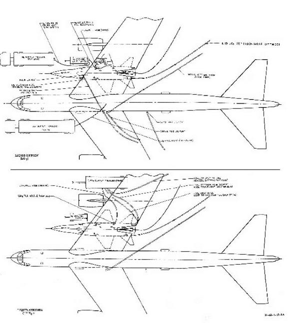
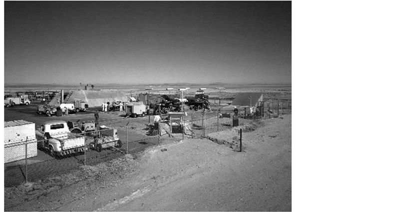
Although simplistic by modern standards, preparation of the X-15 for flight was still a complicated procedure involving many people and pieces of ground – support equipment. These drawings show the relative placement of tank trucks and other equipment during the loading of liquid oxygen and anhydrous ammonia prior to flight. (NASA)

In June 1960 the Air Force installed an AN/APN-41 radar transponder in the NB-52A that allowed the High Range to track the carrier aircraft more accurately. This beacon was similar to the one installed in the X-15. The problem had been that the B-52 fuselage was often located between the X-15 beacon and the radar site before launch and acted as an effective shield. Installing a beacon on the B-52 avoided the problem. A series of test flights that made simulated launches from Silver Lake (the NB-52 did not carry the X-15 for the tests) showed that using the beacon to position the B-52 resulted in a more accurate launch location than had previously been attained. This provided an extra margin of safety should the X-15 pilot have to make an emergency landing, and also allowed flight profiles to be repeated more accurately, helping post-flight analysis. The NB-52B received a similar beacon during July 1960. Flight 1-9-17 on 4 August 1960 was the first flight to use the new beacon.-1126

In June 1965 the FRC estimated that the full-up weight of the X-15A-2 with a real ramjet and fuel had grown to 56,000 pounds. This was more than 1,000 pounds greater than the most recent analysis showed the NB-52 wing/pylon could safely tolerate. In January and February 1966 the Air Force modified the NB-52A to increase the allowable pylon weight to 65,000 pounds, allowing for the heaviest expected X-15A-2 flight with some reserve for gusts or other contingencies. The modifications consisted primarily of installing doublers and additional fasteners on various parts of the wing and pylon structure. Although the modifications allowed the NB-52 to carry the X – 15A-2 safely, performance suffered. For instance, the maximum launch altitude was 1,500 feet lower and the maximum launch speed was restricted to about Mach 0.8 when the research airplane carried the external tanks and ramjet. The Air force installed the same modifications on the NB-52B during its next major maintenance period.-1^27

A Hypersonic Research Airplane

The 9 July 1954 meeting at NACA Headquarters and the resulting release of the Langley study served to announce the seriousness of the hypersonic research airplane effort. Accordingly, many government agencies and aircraft manufacturers sent representatives to Langley to examine the project in detail. On 16 July three representatives from the Air Research and Development Command (ARDC)-the Air Force organization that would be responsible for the development of the airplane-visited John Becker to acquaint themselves with the NACA presentation and lay the groundwork for a larger meeting of NACA and ARDC personnel.-11!

Independently of any eventual joint program, approval for the first formal NACA research authorization was granted on 21 July 1954. This covered tests of an 8-inch model of the Langley configuration in the 11-inch hypersonic tunnel to obtain six-component, low-angle-of-attack and five-component, variable-angle-of-attack (to about 50 degrees) data up to Mach 6.86.-12 Research authorizations were the formal paperwork that approved the expenditure of funds or resources on a research project. At the time, it was not unusual-or worthy of comment-for the NACA laboratories to conduct research without approval from higher headquarters or specific funding. This type of oversight would come much later.

During late July, Richard V. Rhode from NACA Headquarters visited Robert R. Gilruth to discuss the proposed use of Inconel X in the new airplane. Rhode indicated that Inconel was "too critical a material" for structural use, and the program should select other materials more representative of those that would be in general use in the future. Rhode later put this in writing, although Langley appears to have ignored the suggestion. This harkened back to the original decision that the research airplane was not meant to represent any possible production configuration (aerodynamically or structurally), but instead was to be optimized for its research role.-13!

A Hypersonic Research Airplane

The overall configuration of the airplane conceived by NACA Langley in 1954 bears a strong resemblance to the eventual X-15. This configuration was used as a basis for the aerodynamic and thermodynamic analyses that took place prior to the contract award to North American Aviation. This drawing accompanied the invitation-to-bid letters during the airframe competition, although it was listed as a "suggested means" of complying with the requirements. (NASA)

On 29 July, Robert J. Woods and Krafft A. Ehricke from Bell Aircraft visited Langley as part of the continuing exchange of data with the industry. On 9 August, the Wright Air Development Center (WADC) sent representatives from the Power Plant Laboratory to discuss rocket engines, in particular the Hermes A1 that Langley had tentatively identified for use in the new research airplane. The WADC representatives went away unimpressed with the selection. The next day Duane Morris and Kermit Van Every from Douglas visited Langley to exchange details of their Model 671 (D-558-3) study with the Becker team, providing a useful flow of information between the two groups that had conducted the most research into the problem to date.^4-

The Power Plant Laboratory emphasized that the proposed Hermes engine was not a man-rated design, but concluded that no existing engine fully satisfied the NACA requirements. In addition, since the Hermes was a missile engine, it could only operate successfully once or twice, and it appeared difficult to incorporate the ability to throttle or restart during flight. As alternatives to the Hermes, the laboratory investigated several other engines, but suggested postponing the engine selection until the propulsion requirements were better defined.^5-

The Hermes engine idea did not die easily, however. As late as 6 December 1954, K. W. Mattison,^6 a sales engineer from the guided-missile department of the General Electric Company, visited John Becker, Max Faget, and Harley Soule at Langley to discuss using the A1 engine in the new airplane. Mattison was interested in the status of the project (already approved by that time), the engine requirements, and the likely schedule. He explained that although the Hermes engines were intended for missile use, he was certain that design changes would increase the "confidence level" for using them in a manned aircraft. He was not sure, however, that General Electric would be interested in the idea.[7]

ESCAPE SYSTEM DEVELOPMENT

The development of an escape system had been the subject of debate since the beginning of the X-15 program. North American’s decision to use a combination of an ejection seat and a full – pressure suit was a compromise based largely on the ejection seat being lighter than the other alternatives. It was also heavily lobbied for by Scott Crossfield.

The Aero Medical Laboratory had recommended an escape capsule, as prescribed by existing Air Force regulations, as early as 8 February 1955. However, the laboratory admitted that an escape capsule would require a long development period and would probably be unacceptably heavy. The laboratory’s alternative was an ejection seat with limb restraints used together with a full – pressure suit. Meetings held during October and November 1955 resulted in a direction to North American to develop an ejection seat that would incorporate head and limb restraints. The Air Force also told North American to document the rationale for adopting such a system.!1281

Privately, Scott Crossfield had already decided he did not like capsule designs. Part of this came from experience with the Douglas D-558-2 program. According to Crossfield, "We had a capsule nose on the Skyrocket but knew from the wind-tunnel data that if you separated the nose from the fuselage, the g-force would be so great it could kill you. I made up my mind I would never use the Skyrocket capsule. I would ride the ship down and bail out." Later events with a similar system on the X-2 would prove this fear correct.!1291

The North American analysis of potential accidents that could cause the pilot to abandon the X – 15 produced some surprising results. Despite the high-altitude and high-speed nature of the mission profiles, North American determined that 98% of potential accidents were likely to occur at dynamic pressures below 1,500 psi, Mach numbers below 4.0, and altitudes less than 120,000 feet. Using these as criteria, North American investigated four potential escape systems: fuselage – type capsules, cockpit capsules, encapsulated seats, and open ejection seats. The comparison included such factors as cockpit mobility, escape potential, mechanical reliability, post-separation performance, and airframe compatibility. This effort took some 7,000 man-hours to complete.

The results showed that an open ejection seat imposed the fewest performance penalties on the aircraft and took the least time to develop. The estimates from North American showed that a satisfactory escape capsule would add 9,000 pounds to the 31,000-pound airplane. Just as importantly, North American—and Scott Crossfield, who would be making the first flights in the airplane-believed the ejection seat offered a better alternative in the event of an emergency, mainly due to its relative mechanical simplicity.-1130!

Despite the report, the Air Force was not completely convinced. During a meeting at Wright Field on 2-3 May 1956, the laboratory again emphasized the perceived limitations of ejection seats. Primarily due to the efforts of Scott Crossfield, the Air Force finally agreed that "the X-15 was probably its own best capsule." The meeting also resulted in another action for North American, once again, to document its rationale for selecting the stable-seat and full-pressure suit combination.-131!

North American held the first formal cockpit inspection in July 1956 at its facility in Inglewood. This inspection featured a fully equipped cockpit mockup, complete with instruments, control sticks, and an ejection seat. The seat was a custom design that featured a new type of pilot restraint harness and small stabilizers to "weather-vane" it into the wind blast and prevent fatal tumbling or oscillation. A solid rocket motor provided about 3,000 lbf to ensure that the seat would clear the X-15. Despite Air Force policy to the contrary, nobody raised any objections about the seat during the inspection. By default, it became part of the official design.-132!

By November 1956, North American had tested a 0.10-scale isolated pilot-seat model of its design in the Naval Supersonic Laboratory wind tunnel at the Massachusetts Institute of Technology (MIT). Although the seat seemed to stabilize randomly in different orientations, the results were generally encouraging. In itself, this did not represent a serious problem, although all participants wanted to understand the dynamics involved. North American conducted additional tests in the Southern California Co-Operative Wind Tunnel in Pasadena to develop the final stabilization system configuration and determine the influence of the forward fuselage without the cockpit canopy.-133!

The debate over the X-15 ejection seat intensified on 27 September 1956 when Captain Milburn G. Apt was killed in the X-2. However, the accident also weakened the case for an escape capsule. The X-2 used a semi-encapsulated system whereby the entire nose of the aircraft, including the cockpit, was blown free of the main fuselage in an emergency. Unfortunately, Bell engineers had expected the pilot to be able to unbuckle his seat straps and manually bail out of the capsule after it separated, something Apt was unable to do. It demonstrated that an encapsulated system was not necessarily the best solution, but then neither was an ejection seat. Almost by definition, piloting X-planes was—and would remain—a dangerous occupation.134

During early 1958, researchers began testing the X-15 ejection seat on the rocket sleds at Edwards, with the preliminary runs concluding on 22 April. The series got off to a good start, with the first test seat ejected at 230 knots and the parachute successfully opening at 120 feet, lowering the anthropomorphic dummy gently to the ground. The dummy was equipped with telemetry that relayed data from rate gyros, accelerometers, and pressure transducers. The second test, this one at 620 knots and a dynamic pressure of 1,130 psf, also went well. The third test, under similar conditions, was again satisfactory. However, during the fourth run the shock­wave generator catapult exploded at Mach 1.26 and 2,192 psf. The accident damaged the seat, suit, and anthropomorphic dummy beyond repair. Engineers fired another seat during a static test on 24 April, but the post-ejection operation failed because of a mechanical problem in the initiation hardware. During the second static test on 14 May 1958, the parachute and parachute lines became tangled with the seat. In all, the test series provided mixed results. North American made several minor modifications in preparation for a second series of tests scheduled for June.-1135!

The high cost of the rocket-sled runs, coupled with the damaged seat hardware, was quickly exceeding the budget for the escape-system tests. Because of this, the X-15 Project Office decided to conduct only two tests, at 125 psf and 1,500 psf. Despite the earlier difficulties, Air Force and North American engineers believed these two tests could adequately demonstrate seat reliability.-1136!

The Air Force conducted the test at 125 psf on 4 June 1958, and the results appeared to be satisfactory. Three successful tests took place during June, but the fourth test, on 3 July, revealed serious stability problems. North American discontinued further tests until it could determine a cause for the failures. A detailed analysis revealed that the seat would need several major modifications.-137!

The Air Force conducted the first test of the revised North American seat on 21 November 1958, but several of the sled rockets failed to ignite and reduced the desired 1,500-psf pressure to about 800 psf. Two tests during December also suffered from the failure of sled rockets. The only test conducted during January failed when the right-hand boom and fin failed to deploy. The leg restraints also failed during the test, but North American believed an instability caused by the boom malfunction caused this. The parachute failed to open until just before the test dummy hit the ground, causing significant damage to the dummy.138!

ESCAPE SYSTEM DEVELOPMENT

The ejection seat for the X-15 was a remarkable engineering achievement, and was the most sophisticated ejection seat yet developed at the time of the first X-15 flight. Still, it was much simpler than an encapsulated ejection system would have been. (U. S. Air Force)

The schedule was getting tight since the X-15 was nearly ready to begin captive-carry flights. On 12 January, the Aircraft Laboratory verbally approved the seat for the initial captive and glide flights between Mach 0.377 and Mach 0.720 at dynamic pressures between 195 and 715 psf. The X-15 Project Office considered this satisfactory given the inability of the NB-52 to go much faster.^

ESCAPE SYSTEM DEVELOPMENT

As developed by North American, the ejection seat contained provisions to restrain the pilot’s arms and legs to keep them from flailing in the airstream after leaving the aircraft, and also booms and canards to stabilize the seat during separation. After the seat left the aircraft, the pilot unbuckled and jumped from the seat, coming down on his own parachute. (North American Aviation)

Because of the unsuccessful January test, North American carefully rechecked and strengthened the booms and pressure-tested the seat’s gas system. The Air Force conducted the final sled-test on 3 March 1959 at Mach 1.15 and 1,600 psf—conditions somewhat in excess of requirements. Despite the failure of the leg manacles, the test was the most successful to date. North American proposed additional tests and a parachute program in April 1959, but the X-15 Project Office was happy with the results of the tests already run and declined. The X-15 finally had an ejection seat.^1401

The pilot used a backpack-type parachute after he separated from the seat. However, because of the design of the pressure suit, seat, and cockpit, neither the Air Force nor North American considered the standard quarter-deployment bag and 28-foot-diameter C-9 parachute acceptable. Instead, North American produced a special 24-foot-diameter chute and "skirt bag" specifically for the X-15. The company extensively tested this combination on a whirltower to verify the design of the skirt bag, the optimum pilot-parachute bridle length, and the effect of having the seat headrest permanently attached to the pilot chute. The tests in early 1958 included opening speeds up to 300 knots, and subsequent free-fall tests with an anthropomorphic dummy released from a Fairchild C-119 Flying Boxcar over the National Parachute Range in El Centro, California. During the initial tests, the C-119 released the dummy in a head-down attitude at 125

knots and 1,200 feet. These tests were unsuccessful because the pilot chute deployed into a low – pressure zone in the wake of the dummy and was not capable of pulling the main chute from the pack. North American extended the bridle length to 70 inches, allowing the pilot chute to escape the low-pressure area, and subsequent tests were successful.-141

Initially North American used the 24-foot diameter chute because it was the largest they could easily accommodate in the backpack and the engineers thought it would open more quickly, allowing safe ejection at lower altitudes. However, several flight surgeons had concerns that it would allow too high a descent rate for the pilot, and urged the certification of a larger parachute for use on the X-15. During October 1960, North American tested a repackaged 28-foot – diameter parachute at the National Parachute Range. These tests were successful and indicated no significant difference in opening time between the smaller and larger chutes. It became policy that each pilot could select whichever size parachute he wished to use. Most continued to use the 24- foot chute because the reduced thickness of the backpack made it more comfortable to sit on in the cockpit.142

In June 1965, NASA authorized North American to purchase five new 28-foot parachutes to replace the 24-foot units that had reached their 7-year service limit. The new chutes had a disconnect device that allowed the pilots to release one-half of the shroud lines during descent. They were less comfortable because they were thicker than the original parachutes, but as personnel at Edwards discarded the smaller units, they became standard.142

Despite the confidence Scott Crossfield and the North American engineers had in the ejection seat, apparently it was not universal. Pete Knight once commented, "They tell me that the seat is good for Mach 4 and 120,000 feet. I take it with a grain of salt, but I think the safest place to be is inside the airplane until we get to a more reasonable environment…. If you had to, as a last resort certainty you would take the chance, but I think most of the pilots have felt that we…would stay with [the airplane] as long as possible." At least everybody agreed that the cockpit was a safe place. Crossfield demonstrated that when the X-15-3 exploded on the ground while he was testing the XLR99 engine.-144-

ESCAPE SYSTEM DEVELOPMENT

The X-15 ejection seat, like all other seats of the era, was tested on the rocket sled track at Edwards AFB, California. The sled test results were mixed, with many failures of both the sled and the seat for various reasons, but ultimately the Air Force, NASA, and North American were satisfied that the seat would work as advertised. (U. S. Air Force)

POST X-15

Of the 11 XLR99 flight engines that were produced during 1958-1960 to support the flight program, one (s/n 105) was destroyed in the 1959 ground accident and another (111) was destroyed in the 1967 crash of the X-15-3. During September 1975, researchers at Edwards conducted an inventory of existing engines and engine spares in anticipation that the engine might possibly be used in a future flight program. Seven flight-rated and one ground-test engine remained at Edwards, but the Air Force had already scrapped the others or given them to museums. Although the engineers thought most piece-parts were available from various sources, three high-cost spares (thrust chamber/injector assemblies, turbopump cases, and igniters) were in short supply.-1114

because of cracks in the tubing or injector spud. Six pump cases ($12,000 each) had been replaced during the X-15 flight program, mainly due to corrosion, and there were eight cases available for future use. Only 10 igniters ($4,000) were available, but the flight program had used 17, mainly due to detonation at shutdown-a condition that Reaction Motors had largely corrected.-1115!

In addition to the possibility of using existing engines in another program, several proposals had been made for augmented or improved versions of the XLR99 to support various projects. The first serious effort was to support the hypersonic research engine (HRE) experiment on the X – 15A-2. On 30 October 1963, Douglas E. Wall, the project manager for airborne hypersonic research at the Aeronautical System Branch at the FRC, wrote to James E. Love, the NASA X-15 program manager, advising him that the X-15A-2 would likely fall far short of the performance requirements for the HRE program.-116!

The region of interest for supersonic combustion testing was from 7,000 to 8,000 fps at dynamic pressures between 1,000 and 2,000 psf. Although Wall cautioned that he could not ascertain the extent of the performance shortfall until after preliminary flight tests, at the time it looked like the X-15A-2 would fall approximately 1,000 fps short. At a meeting held at Wright-Patterson on 25 September 1963, researchers recommended that the X-15 Project Office fund an upgrade to the XLR99, and the AFFTC and FRC representatives proposed three different modifications. The first was the use of an extended nozzle to increase performance at the mid-altitudes (^100,000 feet) for the expected ramjet experiments. The other modifications included a modified injector assembly and the use of a hydrazine fuel additive. Researchers expected that these modifications would take between 12 and 14 months to develop and implement. The X-15 Project Office agreed to look into the matter; however, there appears to be no record indicating that any action was taken.117!

Nevertheless, Reaction Motors did conduct several studies during 1964-1965 on possible improvements to the XLR99. At least one of these investigated the use of axisymmetric and two­dimensional nozzles, and another studied possible improvements to the thrust chamber. Reaction Motors engineers also kept up with the published reports from other rocket-engine manufacturers to see if any of their developments might be applicable to the XLR99.118!

The FRC already had some experience with increasing rocket-engine performance by using nozzle extensions on the Douglas D-558-2. These extensions were small, radiation-cooled members that permitted the rocket exhaust gases to attain higher exit velocities by expanding within the nozzle to ambient pressures. Because of their small size, the extensions had no serious aerodynamic effect or structural design implications. It appeared to researchers at the FRC that a lightweight, radiation-cooled nozzle extension could provide a desirable performance increase for the X-15A-2. The researchers admitted, however, that it would be more difficult to design such a nozzle for the XLR99 than for the XLR11 because of the former’s larger size and more severe operating environment. The size issue loomed largest because there was a possibility of adverse aerodynamic interference with the afterbody flow.119

In order to evaluate this potential, researchers ran a series of wind-tunnel tests that used several different nozzle extension designs. The tests were quite extensive and included various speed brake and horizontal stabilizer positions, ventral stabilizer shapes, and ramjet installations. Tests were conducted over free-stream Mach numbers from 2.3 to 8.0 using the Unitary Plan Tunnel at Langley (Mach numbers up to 4.63) and the von Karman Gas Dynamics Facility Tunnel B at the Air Force Arnold Engineering Development Center (AEDC) at Mach numbers 6.04 and 8.01. To withstand the high Mach numbers, researchers modified the 1/15-scale model to withstand temperatures of 900°F for up to 30 minutes.-1120!

The tests included nozzle extensions of various exit diameters and lengths representing expansion ratios of 22.1:1 to 33.6:1, along with various aerodynamic shrouds to reduce interference effects. In all, researchers investigated nine candidate nozzles, and the tests indicated that none of the nozzle extensions had any appreciable affect on overall drag or static margin, although the 22.2:1 nozzle was most suitable. The use of this nozzle increased the burnout velocity by 400 fps with no other changes to the airplane or engine.-121!

During January 1966, researchers at Langley ran more tests on the 1/15-scale model of the X – 15A-2 in the 4 by 4-foot unitary tunnel. These obtained data on various XLR99 nozzle extensions, including ones with area ratios of 11.2:1, 28.8:1, and 33.6:1 at Mach numbers up to 4.63. The X015 models used in the wind tunnels included various other modifications, including a redesigned aft fuselage boat-tail meant to smooth over the larger engine nozzle. All of the nozzle extensions actually improved the base drag coefficients over the basic configuration, and all exhibited less drag than the boat-tail configurations. Despite the seemingly minor cost of the nozzle modifications, neither the Air Force nor NASA took any action to produce any hardware or perform actual engine or flight tests.122!

In early 1967, Reaction Motors began another investigation of an improved nozzle for the XLR99 designed to increase thrust at high altitudes. The Air Force issued a work order for the study as an extension of the XLR99 engineering support contract, but did not record the exact reason for the study. The new nozzle had an expansion ratio of 22.5:1 instead of the 9.8:1 used on the existing XLR99s, resulting in an increase in vacuum thrust and vacuum-specific impulse of approximately 7% at a chamber pressure of 600 psi. Two percent of that improvement was the result of using a contoured nozzle instead of the 20-degree conical nozzle used on the original 9.8:1 extension.123

During the investigations of the new nozzle, all other parts of the engine remained unchanged, so it would have been easily possible to retrofit existing engines. The new engine produced a specific impulse of 298-lbf-sec/lbm and a thrust of 63,378-lbf in a vacuum. The new engine could be operated at sea level without flow separation, although its performance was somewhat below the standard XLR99 at low altitudes. The recommended nozzle design was an overturned bell nozzle composed of tangent circular arcs with a length and end diameter roughly equivalent to the normal 20-degree conical nozzle. The nozzle was designed with an exit angle of approximately 5 degrees rather than zero. This is because the last few degrees of wall-turning only added weight, since friction losses canceled out the theoretical thrust gain. Again, no further action resulted from the study.123

Perhaps the most ambitious upgrade was the one proposed to support the delta wing X-15 concept. One of the desired missions for the delta-wing airplane was a sustained 1-g Mach 7 cruise capability, and Reaction Motors sought a way to allow the XLR99 to act as a "sustainer" engine producing 8,000-10,000 lbf for several minutes at a time. The company investigated two different possibilities to provide the sustainer capability. The first used the existing XLR99 chamber to provide the same 57,000-lbf thrust and a separate, remotely located chamber to provide additional thrust during main engine operation and sustainer thrust during cruise. This was conceptually similar to the system used on the Atlas ICBM and the ill-fated Curtiss-Wright XLR25 in the Bell X-2. The second idea was to modify the existing chamber to both provide increased thrust and allow the sustainer function, and to use the previously investigated 22.5:1 expansion ratio nozzle. This second concept was similar to what the 1963 meeting at Wright – Patterson had recommended to fix the X-15A-2 performance shortfall. Reaction Motors estimated that it would take two years to develop and test the modified engine.-1125!

Surprisingly, Reaction Motors preferred using a separate sustainer chamber since it presented less risk and required less development time. Throttling the main chamber produced between 26,000 and 62,000 lbf, and the remote chamber produced between 8,000 and 21,000 lbf. This would have provided an engine capable of infinite throttling between 8,000 and 83,000 lbf. The Air Force disagreed with the risk assessment and considered the problem of integrating a second thrust chamber and nozzle into the X-15 too great, so the delta-wing program selected the single-chamber design despite the longer development time required.-126!

The major constraint imposed in considering the maximum thrust available from modifications to the XLR99 was the number of changes that had to be made to the turbopump. Unlike some other components of the XLR99, the turbopumps had been relatively trouble-free during development and operation. However, because of this lack of problems, nobody was thoroughly familiar with the pumps and their operation. To address this, Reaction Motors brought the original turbopump engineer, Haakon Pedersen, out of retirement. Pedersen proposed relatively modest changes to the turbopump that could provide a 40% increase in pumping capacity. The solution was deceptively simple: speed up the pump. This increased speed was not expected to "generate difficulties with the seals, bearings, or critical speed" or to "affect cavitation adversely." Pedersen did caution that he based these predictions on his own intuition since Reaction Motors had never tested the turbopumps at greater than 100% power. The increased speed, however, required a new turbine because the existing one could not accommodate the 72.5% increase in hydrogen – peroxide flow.122!

There is no record that Reaction Motors ever accomplished any testing on the modified XLR99 or its components. Given that NASA terminated the delta-wing X-15 project early in its development, it is likely that Reaction Motors never modified any hardware.

XB-70

During the course of the X-15 program, various drawings and artist concepts were released that showed the research airplane-particularly the proposed delta-wing version-carried by a North American XB-70 bomber. The use of this Mach 3+ capable aircraft would have greatly extended the performance envelope of the X-15. However, given the theoretical uncertainties of launching an object from the back of a larger aircraft traveling at Mach 3, it is unlikely that the Air Force or NASA ever seriously considered this concept. After the fatal crash on 30 July 1966 of a Lockheed M-21 Blackbird while launching a D-21 drone from a similar configuration, it became even more unlikely. Nevertheless, sometime during 1966 North American conducted a study (logically called "XB-70/X-15"); unfortunately, however, no copy could be found in any archive, so its contents and conclusions are unknown.-1228

XB-70

The use of the Mach 3+ capable XB-70A as a carrier aircraft would have greatly extended the performance envelope of the X-15. However, given the theoretical uncertainties of launching an object from the back of a larger aircraft traveling at Mach 3, coupled with the fact that only two Valkyries were manufactured, it is unlikely that the Air Force or NASA ever seriously considered this concept. (North American Aviation)

DEVELOPING A CONSENSUS

The WADC evaluation of the NACA proposal arrived at ARDC Headquarters on 13 August. Colonel Victor R. Haugen, director of the WADC laboratories, reported that his organization believed the proposal was technically feasible. The only negative comment referred to the absence of a suitable engine. The WADC estimated that the development effort would cost $12,200,000 and take three or four years. The cost estimate included $300,000 for studies, $1,500,000 for design,

$9,500,000 for the development and manufacture of two airplanes, $650,000 for engines and other government-furnished equipment, and $250,000 for modifications to a carrier aircraft. Somewhat prophetically, one WADC official commented informally: "Remember the X-3, the X-5, [and] the X-2 overran 200%. This project won’t get started for twelve million dollars."-81

A four-and-a-half-page paper titled "NACA Views Concerning a New Research Airplane," released in late August 1954, gave a brief background of the problem and attached the Langley study as a possible solution. The paper listed two major problems: "(1) preventing the destruction of the aircraft structure by the direct or indirect effects of aerodynamic heating; and (2) achievement of stability and control at very high altitudes, at very high speeds, and during atmospheric reentry from ballistic flight paths." The paper concluded by stating that the construction of a new research airplane appeared to be feasible and needed to be undertaken at the earliest possible opportunity.-^

A meeting between the Air Force, NACA, Navy, and the Office of the Assistant Secretary of Defense for Research and Development took place on 31 August 1954. There was general agreement that research was needed on aerodynamic heating, "zero-g," and stability and control issues at Mach numbers between 2 and 7 and altitudes up to 400,000 feet. There was also agreement that a single joint project was appropriate. The group believed, however, that the selection of a particular design (referring to the Langley proposal) should not take place until mutually satisfactory requirements were approved at a meeting scheduled for October.-101

Also on 31 August, and continuing on 1 September, a meeting of the NACA Subcommittee on High-Speed Aerodynamics was held at Wallops Island. Dr. Allen E. Puckett from the Hughes Aircraft Company was the chair. John Stack from Langley gave an overview of the proposed research airplane, including a short history of events. He reiterated that the main research objectives of the new airplane were investigations into stability and control at high supersonic speeds, structural heating effects, and aeromedical aspects such as human reactions to weightlessness. He also emphasized that the performance of the new airplane must represent a substantial increment over existing research airplanes and the tactical aircraft then under development. In response to a question about whether an automatically controlled vehicle was appropriate, Stack reiterated that one of the objectives of the proposed program was to study the problems associated with humans at high speeds and altitudes. Additionally, the design of an automatically controlled vehicle would be difficult, delay the procurement, and reduce the value of the airplane as a research tool.-11 design of the airplane" and that the establishment of a design competition was the most desirable course of action. The subcommittee forwarded the recommendation to the Committee on Aerodynamics for further consideration.-1121

Major General Floyd B. Wood, the ARDC deputy commander for technical operations, forwarded an endorsement of the NACA proposal to Air Force Headquarters on 13 September 1954, recommending that the Air Force "initiate a project to design, construct, and operate a new research aircraft similar to that suggested by NACA without delay." Wood reiterated that the resulting vehicle should be a pure research airplane, not a prototype of any potential weapon system or operational vehicle. The ARDC concluded that the design and fabrication of the airplane would take about 3.5 years. In a change from how previous projects were structured, Wood suggested that the Air Force should assume "sole executive responsibility," but the research airplanes should be transferred to the NACA after a short Air Force airworthiness demonstration program.-121

During late September, John R. Clark from Chance-Vought met with Ira H. Abbot at NACA Headquarters and expressed interest in the new project. He indicated that he personally would like to see his company build the aircraft. It was ironic since Chance-Vought would elect not to submit a proposal when the time came. Many other airframe manufacturer representatives would express similar thoughts, usually with the same results. It was hard to see how anybody could make money building only two airplanes.141

The deputy director of research and development at Air Force Headquarters, Brigadier General Benjamin S. Kelsey, confirmed on 4 October 1954 that the new research airplane would be a joint USAF-Navy-NACA project with a 1-B priority in the national procurement scheme and $300,000 in FY55 funding to get started.15

At the same time, the NACA Committee on Aerodynamics met in regular session on 4 October 1954 at Ames, with Preston R. Bassett from the Sperry Gyroscope Company as chairman. The recommendation forwarded from the 31 August meeting of the Subcommittee on High-Speed Aerodynamics was the major agenda item. The following day the committee met in executive session at the HSFS to come to some final decision about the desirability of a manned hypersonic research airplane. During the meeting, various committee members, including De Elroy Beeler,

Walt Williams, and research pilot A. Scott Crossfield, reviewed historic and technical data. Williams’s support was crucial. Crossfield would later describe Williams as "the man of the 20th Century who made more U. S. advanced aeronautical and space programs succeed than all the others together. He was a very strong influence in getting the X-15 program launched in the right direction." Williams would later do the same for Project Mercury.161

The session at the HSFS stirred more emotion than the earlier meeting in Washington. First, Beeler discussed some of the more general results obtained previously with various research airplanes. Then Milton B. Ames, Jr., the committee secretary, distributed copies of the NACA "Views" document. Langley’s associate director, Floyd Thompson, reminded the committee of the major conclusion expressed by the Brown-O’Sullivan-Zimmerman study group in June 1953: that it was impossible to study certain salient aspects of hypersonic flight at altitudes between 12 and 50 miles in wind tunnels due to technical limitations of the facilities. Examples included "the distortion of the aircraft structure by the direct or indirect effects of aerodynamic heating" and "stability and control at very high altitudes at very high speeds, and during atmospheric reentry from ballistic flight paths." The study admitted that the rocket-model program at Wallops Island could investigate aircraft design and operational problems to about Mach 10, but this program of subscale models was not an "adequate substitute" for full-scale flights. Having concluded that the

Brown group was right, and that the only immediate way known to solve these problems was to use a manned aircraft, Thompson said that various NACA laboratories had then examined the feasibility of designing a hypersonic research airplane. Trying to prevent an internal fight, Thompson explained that the results from Langley contained in the document Milton Ames had just distributed were "generally similar" to those obtained in the other NACA studies (which they were not), but were more detailed than the other laboratories’ results (which they were).[17]

Williams and Crossfield followed with an outline of the performance required for a new research airplane and a discussion of the more important operational aspects of the vehicle. At that point, John Becker and Norris Dow took over with a detailed presentation of their six-month study.

Lively debate followed, with most members of the committee, including Clark Millikan and Robert Woods, strongly supporting the idea of the hypersonic research airplane.

Surprisingly, Clarence L. "Kelly" Johnson, the Lockheed representative, opposed any extension of the manned research airplane program. Johnson argued that experience with research aircraft had been "generally unsatisfactory" since the aerodynamic designs were inferior to tactical aircraft by the time research flights began. He felt that a number of research airplanes had developed "startling performances" only by using rocket engines and flying essentially "in a vacuum" (as related to operational requirements). Johnson pointed out that "when there is no drag [at high altitude], the rocket engine can propel even mediocre aerodynamic forms to high Mach numbers." These flights had mainly proved "the bravery of the test pilots," Johnson charged. The test flights generated data on stability and control at high Mach numbers, Johnson admitted, but aircraft manufacturers could not use much of this information because it was "not typical of airplanes actually designed for supersonic flight speeds." He recommended that they use an unmanned vehicle to gather the required data instead of building a new manned airplane. If aeromedical problems became "predominant," Johnson said, a manned research airplane could then be designed and built, and it should have a secondary role as a strategic reconnaissance vehicle.[18]

DEVELOPING A CONSENSUS

Clarence L "Kelly"Johnson, the legendary founder of the Lockheed Skunk Works, was the only representative on the NACA Committee on Aerodynamics to vote against proceeding with the development of the X-15. Previous X-plane experience had left Johnson jaded since the performance of the research airplanes was not significantly advanced from operational prototypes. As it turned out, the X-15 would be the exception, since no operational vehicle, except the Space Shuttle, has yet approached the velocity and altitude marks reached by the X-15. (Lockheed Martin)

into flight research in the shortest time possible." In comparing manned research airplane operations with unmanned, automatically controlled vehicles, Crowley noted that the X-1 and other research airplanes had made hundreds of successful flights despite numerous malfunctions.-1191 In spite of the difficulties—which, Crowley readily admitted, had occasionally caused the aircraft to go out of control—research pilots had successfully landed the aircraft an overwhelming percentage of the time. In each case the human pilot permitted further flights to explore the conditions experienced, and in Crowley’s opinion, automated flight did not allow the same capabilities.-1291

After some further discussion, and despite Johnson’s objections, the committee passed a resolution recommending the construction of a hypersonic research aircraft:1211

ВЕЙОІЛЯЮЙ люга» ВТ NACA.

соиштёе oil ашфшамюэ, 5 ocrcam 1954

VKCREAS, The весе в з It/ of supremacy

In the air continues to place great urgency on solving the problems of flight with man-carrying aircraft at greater speeds and extreme altitudes, rth-i

МВДЩЦЗ, Ргордіа ion systems are now capable of propelling eufih aircraft to speeds and altlt^ea that Impose entirely new and unexplored aircraft design problems, and

WHEftEAS, It now appears feasible to construct a research airplane capable of initial eirploraticn of these problems,

HE ГГ HHtiW RESOLVED, That iJie Ccamlttee on Aerodynamics sudarses the proposal of the tetuadlata Initiation of a project to design and construct a research airplane capable of aohleving speeds of the order of №oh Number 7 and altitudes of several hundred thousand feet for the exploration of the problems of stability and control of maimed aircraft and aerodynamic heating In the severe form associated with flight at extreme speeds and altitudes.

The "requirements" of the resolution conformed to the conclusions from Langley, but were sufficiently general to encourage fresh approaches. Appended to the specification under the heading of "Suggested Means of Meeting the General Requirements" was a section outlining the key results of the Becker study.1221

Kelly Johnson was the only member to vote nay. Sixteen days after the meeting, Johnson sent a "Minority Opinion of Extremely High Altitude Research Airplane" to Milton Ames with a request that it be appended to the majority report, which it was.1231

On 6 October 1954, Air Force Headquarters issued Technical Program Requirement 1-1 to initiate a new manned research airplane program "generally in accordance with the NACA Secret report, subject: ‘NACA Views Concerning a New Research Aircraft’ dated August 1954." The entire project was classified Confidential. The ARDC followed this on 26 October with Technical Requirement 54 (which, surprisingly, was unclassified).1241

In the meantime, Hartley Soule and Clotaire Wood held two meetings in Washington on 13 October. The first was with Abraham Hyatt at the Navy Bureau of Aeronautics (BuAer) to obtain the Navy’s recommendations regarding the specifications. The only significant request was that provisions should exist to fly an "observer" in place of the normal research instrumentation package. This was the first (and nearly the only) official request from the Navy regarding the new airplane, excepting the engine. In the second meeting, Soule discussed the specifications with Colonel R. M. Wray and Colonel Walter P. Maiersperger at the Pentagon, and neither had any significant comments or suggestions.

With an endorsement in hand, on 18 October Hugh Dryden conferred with Air Force (colonels Wray and Maiersperger) and Navy (Admiral Robert S. Hatcher from BuAer and Captain W. C.

Fortune from the ONR) representatives on how best to move toward procurement. The parties agreed that detailed technical specifications for the proposed aircraft, with a section outlining the Becker study, should be presented to the Department of Defense Air Technical Advisory Panel by the end of the year. The Navy reiterated its desire that the airplane carry two crew members, since the observer could concentrate on the physiological aspects of the flights and relieve the pilot of that burden. The NACA representatives were not convinced that the weight and cost of an observer could be justified, and proposed that the competing contractors decide what was best.

All agreed this was appropriate. Again, the Air Force requested little in the way of changes.-1251

Hartley Soule met with representatives of the various WADC laboratories on 22 October to discuss the tentative specifications for the airplane. Perhaps the major decision was to have BuAer and the Power Plant Laboratory jointly prepare a separate specification for the engine. The complete specification (airplane and engine) was to be ready by 17 November. In effect, this broke the procurement into two separate but related competitions: one for the airframe and one for the engine.

During this meeting, John B. Trenholm from the WADC Fighter Aircraft Division suggested building at least three airplanes, proposing for the first time more than the two aircraft contained in the WADC cost estimate. There was also a discussion concerning the construction of a dedicated structural test article. It seemed like a good idea, but nobody could figure out how to test it under meaningful temperature conditions, so the group deferred the matter.

Also on 22 October, Brigadier General Benjamin Kelsey and Dr. Albert Lombard from Air Force Headquarters, plus admirals Lloyd Harrison and Robert Hatcher from BuAer, visited Hugh Dryden and Gus Crowley at NACA Headquarters to discuss a proposed Memorandum of Understanding (MoU) for conducting the new research airplane program. Only minor changes to a draft prepared by Dryden were suggested.-261 The military representatives told Dryden that a method of funding the project had not been determined, but the Air Force and Navy would arrive at a mutually acceptable agreement for financing the design and development phases. During the 1940s and 1950s it was normal for the military services to fund the development and construction of aircraft (such as the X-1 and D-558, among others) for the NACA to use in its flight research programs. The aircraft resulting from this MoU would be the fastest, highest-flying, and by far the most expensive of these joint projects.

The MoU provided that technical direction of the research project would be the responsibility of the NACA, acting "with the advice and assistance of a Research Airplane Committee" composed of one representative each from the Air Force, Navy, and the NACA. The New Developments Office of the Fighter Aircraft Division at Wright Field would manage the development phase of the project. The NACA would conduct the flight research, and the Navy was essentially left paying part of the bills with little active roll in the project, although it would later supply biomedical expertise and a

single pilot. The NACA and the Research Airplane Committee would disseminate the research results to the military services and aircraft industry as appropriate based on various security considerations. The concluding statement on the MoU was, "Accomplishment of this project is a matter of national urgency."[27]

The final MoU was originated by Trevor Gardner, Air Force Special Assistant for Research and Development, in early November 1954 and forwarded for the signatures of James H. Smith, Jr., Assistant Secretary of the Navy for Air, and Hugh L. Dryden, director of the NACA, respectively. Dryden signed the MoU on 23 December 1954 and returned executed copies to the Air Force and Navy.[28]

John Becker, Norris Dow, and Hartley Soule made a formal presentation to the Department of Defense Air Technical Advisory Panel on 14 December 1954. The panel approved the program, with the anticipated $12.2 million cost coming from Department of Defense contingency funds as well as Air Force and Navy research and development funds.-129

After the Christmas holidays, on 30 December, the Air Force sent invitation-to-bid letters to Bell, Boeing, Chance-Vought, Convair, Douglas, Grumman, Lockheed, Martin, McDonnell, North American, Northrop, and Republic. Interested companies were asked to attend the bidders’ conference on 18 January 1955 after notifying the procurement officer no later than 10 January. An abstract of the NACA Langley study was attached with a notice that it was "representative of possible solutions" but not a requirement to be satisfied.-129

DEVELOPING A CONSENSUS

Also accompanying the invitation-to-bid letters was a simple chart that showed the expected flight trajectory for the new research airplane. It was expected that each flight would provide about 130 seconds of good research data after engine burnout. This performance was almost exactly duplicated by the X-15 over the course of the flight program. (NASA)

This was undoubtedly the largest invitation-to-bid list yet for an X-plane, but many contractors were uncertain about its prospects. Since it was not a production contract, the potential profits were limited. Given the significant technical challenges, the possibility of failure was high. Of course, the state-of-the-art experience and public-relations benefits were potentially invaluable. It was a difficult choice even before Wall Street and stock prices became paramount. Ultimately, Grumman, Lockheed, and Martin expressed little interest and did not attend the bidders’ conference, leaving nine possible competitors. At the bidders’ conference, representatives from the remaining contractors met with Air Force and NACA personnel to discuss the competition and

the basic design requirements. The list of participants read like a Who’s Who of the aviation world. Robert Woods and Walter Dornberger from Bell attended. Boeing sent George Martin, the designer of the B-47. Ed Heinemann from Douglas was there. Northrop sent William Ballhaus.-131

During the bidders’ conference the Air Force announced that each company could submit one prime and one alternate proposal that might offer an unconventional but potentially superior solution. The Air Force also informed the prospective contractors that an engineering study only would be required for a modified aircraft in which an observer replaced the research instrumentation, per the stated Navy preference. A significant requirement was that the aircraft had to be capable of attaining a velocity of 6,600 fps and altitudes of 250,000 feet. Other clarifications included that the design would need to allocate 800 pounds, 40 cubic feet, and 2.25 kilowatts of power for research instrumentation. A requirement that would come back to haunt the procurement was that flight tests had to begin within 30 months of contract award.

STABLE PLATFORM DEVELOPMENT

Another major piece of government-furnished equipment was the all-attitude inertial system, called a "stable platform" at the time. Early on, researchers realized the performance of the research airplane required a new method to determine altitude, speed, and attitude information. The original Langley study, as well as each of the contractor proposals, had suggested the use of a stable platform. Unfortunately, such as system was not readily available.

A meeting held at Wright Field on 14-15 November 1955 implied that the WADC would furnish the stable platform. Arthur Vogeley, the NACA representative, assumed that the Air Force had already developed a suitable device since his report stated that a newly developed Bendix platform weighed only 28 pounds and occupied less than a cubic foot of volume. Others within the NACA and North American were not as certain. During a meeting with North American personnel, Walt Williams specifically asked who was responsible for the stable platform, and no answer was immediately forthcoming.-1145!

Researchers apparently did not discuss the requirements for a stable platform until 24 May 1956 during a meeting at Langley. In attendance were representatives from Eclipse-Pioneer (a division of Bendix), the NACA, North American, and the WADC. This group discussed the platform mentioned at the November 1955 meeting, and Eclipse-Pioneer acknowledged that it was only a conceptual design and not a forthcoming product. Nevertheless, the meeting attendees thought

that development of a suitable platform would take only 24 months. Since the platform provided research data in addition to flight data, the NACA agreed to charge 40 pounds of the estimated 65-pound weight against research instrumentation. There was no mention as to why the original 28-pound estimate had grown to 65 pounds.-146

Despite its early participation, Eclipse-Pioneer did not exhibit any further interest, so the Flight Control Laboratory asked the Sperry Gyroscope Company if it was interested. By August 1956, Sperry had prepared a preliminary proposal, and on 4 October the X-15 Project Office held a technical briefing for Sperry at Wright Field.147

On 26 December 1956, the Flight Control Laboratory began the process to procure eight inertial flight data systems (six "Type A" units for the X-15 and two "Type B" units for ground research). The laboratory recommended awarding the $1,030,000 contract to the Sperry Gyroscope Company.-1148!

For unexplained reasons, the Air Materiel Command did not take immediate action and did not release a formal request for proposal to Sperry until 6 February 1957. Two weeks later Sperry replied, and the Flight Control Laboratory approved the technical aspects of the proposal on 28 March. In the meantime, however, a controversy had developed over contracting details. The negotiations reached a deadlock on 11 April 1957 and the Air Materiel Command informed the X – 15 Project Office that it intended to find another contractor. The Flight Control Laboratory and X – 15 Project Office argued that Sperry was the only company that stood a chance of meeting the X – 15 flight schedule, but procurements were the domain of the Air Materiel Command and the warnings fell on deaf ears.-1149!

It was evident that the issue was rapidly exhausting the patience of all concerned. On 22 April 1957, the director of development at the WADC, Brigadier General Victor R. Haugen, informed the Air Materiel Command that Sperry was the only company capable of developing the stable platform within the schedule constraints of the X-15 program. Having a general officer intervene was apparently the answer, and a cost-plus-fixed-fee contract signed on 5 June 1957 provided $1,213,518.06 with an $85,000 fee.156

Because of the contracting delays, the expected December 1958 delivery of the initial Sperry unit would not support the first flight of the X-15. This was not a significant problem since the initial X-15 flights would be low and slow enough to use a standard NACA flight test boom to provide the data ultimately supplied by the stable platform and ball nose. In fact, the NACA would likely have used the flight test boom even if the other instruments had been available, since it provided a known, calibrated source for acquiring initial air data. Most experimental aircraft use similar booms during early testing.151

More disturbing, however, was that it quickly became apparent that the weight of the stable platform had been seriously underestimated. In May 1958, Sperry undertook a weight-reduction program that, unfortunately, was particularly unsuccessful. By August, Sperry was reporting that the weight was approximately twice the original specification.157

It was just the beginning of serious trouble. By June 1958, the estimated cost was up to $2,741,375 with a $105,000 fee. Less than a year later the cost reached $3,234,188.87 with an $119,888 fee, mostly due to efforts to reduce the weight of the stable platform.157

specification, the system weighed 185.25 pounds. An alternate shock mount that did not meet the requirements but was probably acceptable brought the weight down to 165.25 pounds. Interestingly, Sperry admitted it had known about the weight problem for some time, but did not explain why it had not brought the issue to the government’s attention at an earlier date.-1154

Sperry defended its actions by listing the changes it had made to eliminate excess weight. These included substituting aluminum for stainless steel in some locations, reducing the thickness of various covers, and reducing component weight wherever practical. The need to include power supplies not anticipated in the original proposal also increased the weight of the system. Finally, Sperry also concluded that the stable platform was lighter and more accurate than any competing system. Apparently, Sperry’s justification was satisfactory since the X-15 Project Office accepted that the system was going to remain overweight and took no further action on the subject.[155]

As finally delivered, the stable platform was an Earth-slaved, Schuler-tuned system aligned in azimuth to a guidance vector coincident with X-15 centerline. The unit provided attitude, velocity, and altitude to the pilot with reference to these coordinate systems. There were three major components to the stable platform: the stabilizer, computer, and displays. Together they weighed approximately 165 pounds, occupied about 3 cubic feet of volume, and required a peak electrical load of 600 W. The stabilizer used three self-balancing accelerometers and three single-degree – of-freedom gyroscopes. A four-gimbal system provided complete attitude freedom in all axes.

An analog computer computed velocity and position data, and applied the necessary acceleration corrections. The computer was shock-mounted and shaped to conform to the contours of the X – 15 instrumentation compartment. Gaseous nitrogen from the X-15 cooled the stabilizer and computer to counteract the internal heat generated by the units, and the extreme external temperatures. The system was "designed to operate over a limited portion of the Earth’s surface." Specifically, it could accept a launch point anywhere within a 275-mile-wide corridor extending 620 miles uprange and 205 miles downrange from Edwards AFB.[156]

Sperry shipped the first stabilizer and computer to Edwards in late January 1959, and the Air Force intended to use the NB-52 carrier aircraft as a test vehicle. This was delayed for unknown reasons, so the Air Force made a KC-97 that was already being used for similar purposes by the Convair B-58 program available to the X-15 project. The first flights in the KC-97 took place in late April, but were of limited value given the low speed of the piston-powered Stratocruiser. In June 1959, North American successfully installed the Sperry system in X-15-3 prior to its delivery to Edwards. By the end of May 1960, there were four complete stable platforms at Edwards: one in X-15-1, one in X-15-3, one spare, and one undergoing repair.-1157

As delivered, the stable platforms could provide the following data:[158]

Measurement

Range

Accuracy (rms)

Display

Record

Pitch angle (degrees)

unlimited

0.5

V

V

Roll angle (degrees)

unlimited

0.5

V

V

Yaw angle (degrees)

unlimited

0.5

V

V

II——————— II—————————— II————— ІГ

Altitude (feet)

0-500,000

5,000

V

Total velocity (fps)

7,000

70

V

Downrange velocity (fps)

7,000

50

V

Crossrange velocity (fps)

3,000

50

V

Vertical velocity (fps)

5,000

20

V

However, Sperry had made several compromises during the development of the X-15 stable platform, either to meet schedule or reduce weight. The designers knew that 300 seconds after launch (i. e., as the airplane decelerated to land) the pressure instruments would be adequate for vehicle altitude and velocity data, and that a system capable of operating from carrier aircraft takeoff to X-15 landing would be too heavy and bulky for the X-15. The final design had a very limited operating duration. The pilot aligned the system just before the X-15 separated from the NB-52, and the stable platform provided just 300 seconds of velocity and altitude data, along with 20 minutes of attitude data. This limited operating duration provided some relief for the weight problem.-115^

As it turned out, the lighter shock mount developed by Sperry was not adequate for the X-15. It performed fine during the XLR11 flights, but vibration tests in October 1960 prior to the beginning of XLR99 tests showed that the mount would not withstand more than 1.5 g at 110 cycles. North American redesigned the mount, since by this time saving weight had become a non-issue for the most part; having a reliable airplane was worth more than the few miles per hour the weight cost.

Over the course of the flight program, the stable platform was the subject of several other changes that greatly improved its reliability. Many of these were the result of suggestions from John Hursh at the MIT Instrumentation Laboratory and Dr. Allen Smith from Ames, both of whom spent a great deal of time at the Flight Research Center during late 1960 working on the problems. As an example of these changes, NASA changed all critical germanium transistor amplifiers to silicon during November 1960. NASA also made changes to operating procedures as well as to hardware. Initially, a gyroscope failure required that the entire stable platform be returned to Sperry for repair, taking the unit off flight status for three to six weeks. In response, the FRC developed an in-house repair capability that significantly shortened turnaround times. Even better, during late 1960 NASA substituted a higher-quality gyroscope manufactured by Minneapolis-Honeywell, which resulted in fewer failures.-1160

STABLE PLATFORM DEVELOPMENT

The X-15 was one of the first aircraft to require what is today called an inertial measurement unit, or stable-platform. Gyroscopes of the era were large, heavy, and consumed a considerable amount of power. This model shows the three interlocked rings required to determine position in three dimensions. (NASA)

In retrospect, the performance specifications established in 1956 were well beyond the state of the art with respect to available gyros, accelerometers, transistors, and circuit techniques.

However, the system as originally built was able to perform at levels that, although marginal or subpar compared to the original specification, still allowed the X-15 to realize its full performance capabilities. Compared to modern laser-ring-gyro and GPS-augmented systems, the X-15 stable platform was woefully inaccurate, but it routinely bettered its 70-fps error specification for velocity. Initially its altitude-measuring ability was somewhat substandard, averaging about 2,200 feet (rms) uncertainty. The requirement was 2,000 feet, but the system eventually improved and met its specification. Reliability was initially poor, but by mid-1961 the overall reliability was approaching the high 90th percentile, with the altimeter function proving to be the most unreliable. Unfortunately, this improved reliability proved to be short-lived.-1161

The initial operational experience with the stable platform showed that it had a large error potential that grew as time passed from the initial alignment due to drift and integration noise. The unit integrated velocities to provide distance (X, Y, and Z) and specifically altitude, which had even more error buildup with time. Early flight tests showed that the displayed velocities were marginal even after the 90-second engine burn, and that the altitude was undependable for determining peak altitude or reentry setup. Because of this, the flight planners and pilots began to consider two other sources for controlling the energy imparted to the airplane: 1) engine burn time, as measured by a stopwatch in the NASA-1 control room, and 2) radar-measured velocity,

[1621

as displayed in the control room.

For the first government flight (2-13-26) with the XLR99 engine, the flight planners decided to use radar velocity as the primary indication with a radio call to Bob White at the desired engine shutdown condition. After the successful flight, researchers calculated that the airplane had exceeded the intended speed by about half a Mach number. Further analysis showed that the radar velocity display in the control room incorporated considerable smoothing of the data to provide a readable output. This introduced a lag of 4 seconds between the actual speed and the displayed speed, thus accounting for the overshoot. For the next few flights, NASA-1 started a stopwatch in the control room at the indication of chamber pressure on the telemetry, and radioed the pilot when it was time to shut down the engine.-163

Using a stopwatch to measure powered flight time proved to be the simplest and yet most accurate method of controlling energy, so a stopwatch was installed in the cockpit of all three airplanes. A signal from the main propellant valves started and stopped the stopwatch so that it displayed the total burn time even after shutdown. The pilot could then assess whether he had more or less energy than planned, and evaluate his energy condition and best emergency lake in the event of a premature shutdown. Although the reliability of the stable platform increased considerably during the course of the program and was eventually operating within its design specifications, the pilots continued to use the stopwatch (with a backup stopwatch in the control room) for most flights. It was cheap and easy, and almost never failed.164

By 1963 an increasing number of stable platform failures began to occur—some because of design deficiencies, others simply due to component deterioration. This led to NASA placing a new set of restrictions on X-15 flights, keeping them below 160,000 feet. Progress by Sperry to resolve the issues was slow, so an analysis was undertaken at the FRC to determine what in-house efforts could be made to bolster system performance and improve reliability.163

Beginning in late 1963, the FRC began redesigning critical components to improve both accuracy and reliability. Eventually, NASA engineers redesigned some 60% of the subassemblies in the stable platform. Overall, the volume used by the accelerometers, accelerometer electronics, and power supplies was reduced over 50%, and an accompanying reduction in power and cooling requirements was also realized. Although some of the improvements resulted from correcting deficiencies in the original design, most were achieved because the state of the art had improved considerably in the four years since work had begun. NASA completed the initial redesign efforts on the accelerometer loops and power supplies during the summer of 1964, and the first flight of the new components was in X-15-2 on 14 August 1964 (2-33-56). Technicians subsequently installed the revised components in X-15-3 also. This system allowed NASA to cancel the 160,000-foot altitude restriction on the airplanes.

Although the initial performance of the revised components was a little erratic, the increase in accuracy was substantial. For instance, 400 seconds into the flight the original system would have a +8,000-foot error in altitude; the revised system generally had a -1,000-foot error. (In both cases the specification required a less than -5,000-foot error; nothing on the positive side was satisfactory.) Eventually the engineers tuned the erratic performance out of the system. By May 1966, components designed at the FRC had essentially replaced the entire Sperry stable platform, and the system was redesignated the "FRC-66 Analog Inertial System."166

STABLE PLATFORM DEVELOPMENTand a set of pilot displays. This system was even smaller and required less power and cooling than the redesigned FRC-66 analog system. In addition, the X-20 IFDS could automatically erect itself and perform an alignment cycle on the ground while the NB-52 was taxiing, and completely eliminated the need for information from the N-1 compass and APN-81 Doppler radar on the NB – 52. This made it somewhat easier to pilot the carrier aircraft as the X-15 approached the launch position; the APN-81 took 90 seconds to stabilize after even a gentle turn, requiring the NB-52 pilot to think well ahead of the drop time. To improve accuracy, however, the IFDS altitude loop was synched to the NB-52 pressure altimeter until 1 minute before launch.-1167

The inertial measurement unit was a gyrostabilized, four-gimbaled platform that maintained local vertical orientation throughout the flight. The inner platform contained three pendulous accelerometers that formed an orthogonal triad. The coupler electronics unit contained the power supplies and interface equipment, and a dual-function digital computer performed all computations. NASA first checked out the digital system in X-15-1 on 15 October 1964 (1-50­79), with satisfactory results.1168

The overall performance of the IFDS during its first 16 flight attempts was excellent, with only two failures. However, problems with the IFDS caused two attempted launches in a row (1-A-105 and 1-A-106) to abort during June 1966. After the first abort, technicians replaced a relay and fixed a loose wire, but the second flight attempt a week later ended the same way. Engineers from Autonetics (a division of North American), Honeywell, the FRC, and Wright Field began investigating the problem. The failures were determined to be the result of yet more wiring problems, all easily corrected.-168

JH5 RESEARCH SYSTEM

TYPICAL MISSION

Подпись: minus и И» MO KtmiuiUtei

I ill!

Because of limitations in both the gyroscopes and onboard computers, the X-15 stable platform could only function for a limited amount of time in a 275-mile-wide corridor extending 620 miles uprange and 205 miles downrange from Edwards AFB. Later modifications to the system were more reliable and versatile, and at the end of the program, two of the X-15s were using digital inertial flight data systems developed for the Air Force Dyna-Soar program. (NASA)

At the same time, the installation in X-15-3 was not going as well as it had in X-15-1. On 6 January 1965, representatives from Honeywell met with FRC personnel to discuss problems with the installation. There were four primary concerns: cooling and thermal conditions, space availability, cabling, and the interface to the MH-96 adaptive control system. This latter issue was surprising since the X-20 also used a version of the MH-96. Also discussed was the relative accuracy expected from the new system versus data from the ball nose. It was pointed out by the

Honeywell representative that at low velocities there would be a significant difference between the IFDS-computed angle of sideslip and that sensed by the ball nose, but at high velocities the difference should be small.[170]

By April 1965 the FRC had made little progress installing the system in X-15-3, and only X-15-1 was flying with the Honeywell inertial system. Fortunately, by this time the modified Sperry systems were proving to be reliable, and no substantial problems had been experienced by X-15- 2 or X-15-3 since December 1964. Engineers finally installed the Honeywell IFDS in X-15-3 during a weather-induced down period at the end of 1965.-1171

Although the Honeywell IFDS was considered an improvement over the modified Sperry stable platform, the FRC decided that the FRC-66 system was preferred for the Mach 8 flights in the modified X-15A-2, so that airplane never received an IFDS. By the end of 1965, engineers had modified one of the Sperry computers to have Mach 8 scaling coefficients in preparation for the X-15A-2 envelope-expansion program.-1172

The improvements did not stop there. Eventually the FRC modified X-15-3 to include an Ames – developed guidance system that was applicable to future aerospace vehicles. This system coupled the IFDS inertial system, MH-96 adaptive control system, and ball nose to an Alert digital computer to investigate boost guidance command techniques. The navigation functions continued to be performed by the inertial system while the Alert computer handled the research objectives, including providing new displays to the pilot. This program allowed the pilot to fly a velocity – altitude window during boost, a bounded corridor during hypersonic cruise, and a precise corridor during reentry. It was an advanced system, and one that Space Shuttle only duplicated in its waning years.-1173

AEROJET LR91

Although the XLR99 proved to be a remarkably capable research engine given its relatively short development period and limited operational experience, proposals were made from time to time to replace it. Usually these revolved around the idea of using a derivative of the Aerojet LR91 engine. In October 1966, Aerojet-General submitted an unsolicited proposal to North American that detailed the use of the LR91-AJ-7 engine in the X-15. Aerojet probably intended the proposal to support the concept of using an LR91 in the delta-wing modification.12^

The LR91 powered the Titan II ICBM, the Titan II Gemini Launch Vehicle, and the Titan III family of space launch vehicles. Aerojet had delivered over 180 engines at the time of the proposal, and had run more than 1,400 engine tests. The engine was man-rated for the Gemini application and the Titan IIIM developed for the Manned Orbiting Laboratory (MOL). The LR91-AJ-7 developed 100,000 lbf at 250,000 feet using nitrogen tetroxide and Aerozine-50 propellants.12^

Aerojet believed that the engine offered several advantages for the X-15. The storable propellants provided a higher bulk density, allowing additional specific impulse to be stored in the same volume, although Aerojet suggested limiting the X-15 to 92 seconds of powered flight. The propellants also eliminated the liquid-oxygen top-off system in the NB-52s since they had a very low boil-off rate and would not have to be replenished in flight. An autogenous pressurization system provided tank pressurization gases from the engine in proportion to propellant consumption, eliminating the need for separate pressurization gases and their mechanical systems (regulators, valves, etc.).130-

Aerojet pointed out that since the engine was in large-scale (for a rocket engine) and continuous production, costs would be lower, and a continuous-improvement program was in place that could benefit the X-15 program. The major changes to the LR91 configuration for the X-15 included modifying it to operate in a horizontal attitude and strengthening the engine to allow it to be reusable. These changes (especially the one to allow horizontal operation) were not as straightforward as they might seem, and a simple description of them took several pages. The modifications to make the engine reusable also took several pages to describe. Nevertheless, Aerojet believed it could provide an engine quickly-beginning by July 1967 allowed the first X-15 flight in March 1969.131

The government did not take any action on this proposal or others made along similar lines. Although working with liquid oxygen and anhydrous ammonia presented some issues for the ground crews, it was decidedly simpler than dealing with the hypergolic propellants in the LR91. Moreover, nobody readily believed that the engine would be as reliable and reusable as the XLR99 without a major development effort, something the X-15 program could not afford. Although an additional 40,000 pounds of thrust would have more than restored the performance lost due to the continual weight gains on the X-15, in the final analysis it just was not worth the time and money. Maybe it would have been worth it for the delta wing; but then, perhaps not.

CHASE AND SUPPORT AIRCRAFT

In addition to the NB-52s there were numerous chase and support aircraft, mostly provided by the Air Force. The number of chase aircraft differed depending on what the flight profile looked like. The program generally used three chase aircraft on the early low-speed X-15 flights, four on most research flights, and five for the very long-range flights. Of course, all things were variable and additional chase aircraft were not uncommon, particularly during the middle years of the program.

Chase-1 was the prelaunch chase, and was usually a North American F-100F Super Sabre during the early years and a Northrop T-38A Talon later, although NASA used a Douglas F5D Skyray on a couple of occasions. Al White frequently flew this chase during the North American flights, but an Air Force pilot generally flew the airplane once the government took over. Chase-1 took off with the NB-52 and flew formation during the climb-out and cruise to the launch lake. The chase pilot visually verified various parts of the X-15 checklist, such as control surface movements, propellant jettison, ballistic system checks, APU start, and engine priming. The use of the F-100 presented some problems at the beginning of the program because the aircraft could not maintain a low enough speed to fly formation with the NB-52 during a right-hand turn; however, the T-38 proved to be more satisfactory.

Chase-2 was the launch chase and provided assistance for the X-15 pilot in the event of an emergency landing at the launch lake. Chase-2 was usually a Lockheed F-104 Starfighter flown by either another X-15 pilot or a NASA test pilot. The F-100 and T-38 could not produce enough drag to fly the steep final approach used by the X-15, which largely dictated the use of the Starfighter for this role. Conversely, the F-104 could not cruise at 45,000 feet due to its high wing loading, which made it unsuitable as Chase-1. Chase-2 normally stayed below 35,000 feet until 3 minutes before launch, and then went into afterburner and climbed to 45,000 feet just before the X-15 dropped. The pilot trailed the NB-52 during launch and then tried to keep up with the X-15 as it left the launch lake area. It was a futile gesture, but it proved useful on the few occasions in which the X-15 engine failed soon after ignition.

Chase-3 covered landings at the intermediate lakebeds and was usually an F-104 flown by either another X-15 pilot or an Air Force test pilot. Unlike Chases 1 and 2, which took off with the NB – 52, Chase-3 waited until 30 minutes before X-15 launch to take off so that it would have enough fuel to loiter for a while. On flight profiles that had multiple intermediate lakes, Chase-3 would orbit between them. In the event the X-15 had to make an emergency landing, the F-104 would attempt to join up to provide support for the X-15 pilot during final approach and touchdown.

For flights out of Smith Ranch there were two intermediate chases, usually called 3 and 4 (the Edwards chase became Chase-5 in these cases).

CHASE AND SUPPORT AIRCRAFT

The Lockheed F-104 Starfighter was used as a chase airplane and to practice landing maneuvers. In addition to the F-104Ns owned by NASA, various F-104s from the Air Force Flight Test Center were used as needed. (NASA)

Chase-4 covered the Edwards landing area, usually with an Air Force pilot. Again, only an F-104 could keep up with the X-15 in the landing pattern. This chase took off at the same time as Chase-3 and orbited 30-40 miles uprange along the flight path. The pilot began accelerating on cue from NASA-1 in an attempt to intercept the X-15 at the maximum possible speed and altitude as the X-15 descended into the Edwards area. Usually the chase pilot took his cues from the vapor trail left as the X-15 pilot jettisoned his residual propellants, since the research airplane was too small and too dark to acquire visually until the chase pilot was right on top of it. Chase-4 would make a visual inspection of the X-15 as it descended and provide airspeed and altitude callouts to the X-15 pilot during the final approach, in addition to verifying that the ventral had successfully jettisoned and the landing gear extended.-1129

CHASE AND SUPPORT AIRCRAFT

Ferrying men and supplies to the contingency landing sites and High Range stations kept the NASA Douglas R4D (C-47/DC-3) Skytrain busy. In addition, the Air Force used Lockheed C-130 Hercules to move fire trucks and other heavy equipment. The C-130s also carried rescue teams during flight operations to ensure help would arrive swiftly in the event of a major accident.

(NASA)

At times there were other chase aircraft, with a photo-chase or a "rover" being the most frequent. The photo-chase filmed the X-15, although Chase-1 was frequently a two-seater and carried a photographer in the back seat as well. Rover was usually another X-15 pilot who just felt like tagging along. All of the X-15 pilots flew chase aircraft, as did many AFFTC test pilots, and students and instructors from the test-pilot schools at Edwards. The chase pilots (particularly other X-15 pilots) tended to use first names for themselves and the X-15 pilot during radio chatter; alternately, they simply used "chase" (without a number) since there was seldom more than one chase aircraft in the vicinity.

A number of other aircraft provided various support functions. In particular, the program used the NASA Gooney Bird (R4D/DC-3) to ferry men and supplies to the uprange stations and to inspect the lakebeds as necessary. The Air Force used several Lockheed C-130 Hercules turboprops to transport fire engines and other material to the lakebeds and High Range stations for each flight. These aircraft often made several trips per day carrying men and equipment. During the actual flight one of them orbited midway down the flight corridor, usually with a flight surgeon and response team in case the X-15 had to make an emergency landing. The program took safety very seriously.

Piasecki H-21 Shawnee helicopters were also shuttled to the primary emergency landing lake in case of an emergency, and additional H-21s were located at Edwards. These provided a quick means of moving emergency personnel to an accident scene, surveying the runways, and evacuating the X-15 pilot if necessary. The H-21 pilots also knew how to disperse fumes from a damaged X-15 by hovering near the crashed airplane, and they used this technique on at least one occasion, probably saving the life of the X-15 pilot.