Category X-15 EXTENDING THE FRONTIERS OF FLIGHT

THE ENGINE EVALUATION

On 8 June, John Sloop at Lewis submitted the preliminary NACA engine results to Hartley Soule. The rankings were 1) XLR81, 2) XLR30, and 3) XLR73. Lewis also commented on various aspects of the airframe proposals, including propellant systems, engine installation, reaction controls, APUs, and fire extinguishing systems, although it drew no conclusions and did not rank the airframe competitors. The airframe manufacturers had concentrated on two of the possible engines: Bell and Republic opted for the Bell XLR81, while Douglas and North American used the Reaction Motors XLR30. Bell had also included an alternate design that used the XLR30 engine. Nobody had proposed using the Aerojet XLR73.[12]

The Power Plant Laboratory believed that minimum thrust was a critical factor. Reaction Motors indicated that its engine was infinitely variable between 30% and 100% thrust. The Bell engine, however, only had thrust settings of 8,000 and 14,500 lbf. However, since the Bell engine had to be used in multiples to provide sufficient thrust for the research airplane, this meant that the equivalent minimum thrust was 18% for the Bell design (which used three engines) and 14% for the Republic airplane (four engines). Initially, the engine evaluation set the desired lower thrust figure at 25%, resulting in a lower score for the Reaction Motors engine. The X-15 Project Office subsequently raised the lower throttle setting to 30%, and the evaluators then ranked the Reaction Motors engine as slightly better.-113

During the initial evaluation the Power Plant Laboratory found little difference between the Bell and Reaction Motors proposals except for the throttling limits, but the report left the impression that the Air Force favored the Bell design. Statements such as "the Bell engine would have potential tactical application for piloted aircraft use whereas no applications of the RMI engine are foreseen," and "in the event that the XLR73 development does not meet its objectives, the Bell engine would serve as a ‘backup’ in the Air Force inventory" made the laboratory’s feelings clear.-14 Of course, the idea that rocket engines potentially could be used in operational manned aircraft quickly waned as jet engines became more powerful, and this became a moot point.

The final meeting at Wright Field on 14-15 June finalized the ground rules for the engine evaluation. The engine companies attended the early portion of the meeting to present preliminary results from their proposals. The ground rules established by the Air Force, Navy, and NACA representatives included three major areas of consideration: 1) the development capability of the manufacturer, 2) the technical design (including the design approach and the research utility), and 3) the cost.13

On 24 June 1955, NACA Lewis issued a revised ranking of the engine competitors. From a technical perspective (not considering management and other factors), the Lewis rankings were now 1) XLR30, 2) XLR81, and 3) XLR73. The reason given for reversing the rankings of the XLR30 and XLR81 was a shift in the engine-evaluation ground rules. Previously researchers rated the XLR30 lower because of its unsatisfactory throttling limits, but new ground rules relaxed the requirements and elevated the engine’s ranking.

There still seemed to be some confusion over the engine-evaluation process, and yet another meeting at NACA Headquarters on 27 June attempted to ensure that everybody was on the same page. The meeting ended with an understanding that the engine evaluation should determine whether any of the engines was unsuitable for use in the airplane, or whether any engine was so clearly superior that it should be selected regardless of the choice of the winning airframe contractor. If neither of these conditions existed, then whichever engine the airframe contractor selected would be chosen. This was the same conclusion reached previously on 14-15 June, and all of the attendees appeared to be satisfied with the result.-1161

On 1 July, the HSFS sent its engine evaluation to Hartley Soule, ranking the power plants as 1) XLR30, 2) XLR73, and 3) XLR81. The transmittal letter, however, expressed concern about "the lack of development of all three of the proposed engines." Walt Williams again strongly recommended an interim engine for the initial flights of the new research airplane (he suggested the Reaction Motors LR8 based on previous HSFS experience). Since the early flights would be primarily concerned with proving the airworthiness of the airplane, they would not need the full power provided by the final engine. The HSFS believed that the development of the new engine would take longer than most expected, and using an interim engine would allow the flight-test program to begin at an earlier date. To minimize the hazards to personnel and instruments, researchers at the HSFS also recommended that Reaction Motors change the fuel for the XLR30 from anhydrous ammonia to gasoline or jet fuel.13

The Air Force evaluation group pointed out that using two fuels interchangeably in the Bell gas

generator systems would overly complicate the fuel system. The use of a separate system to meet the restart requirement was also expected to create safety and reliability problems. On the other hand, although the Reaction Motors engine was more orthodox than the Bell design, the company had not yet performed many tests on it, and the evaluators correctly predicted that it would have a difficult development. The evaluators noted that both engines would need substantial development being man-rated.-1181

A meeting at Wright Field on 6-7 July attempted to sort out the engine selection. De Beeler, John Sloop, and Arthur Vogeley represented the NACA, Oscar Bessio represented the Navy, and Joseph Rogers led the Air Force contingent. The representatives from the Power Plant Laboratory indicated a preference for the XLR73, with the XLR81 as their second choice, but the NACA participants argued that finishing the development of the Aerojet engine would consume a great deal of time. The Navy considered the XLR30 the best (not surprisingly, since it was a Navy engine), followed by the XLR81. The XLR73 was not considered worthy of further consideration because of unspecified "extremely difficult development problems."

The final evaluation report stated that none of the engines was clearly superior or deficient, and therefore the airframe contractor would select the most advantageous engine. The XLR73 was effectively eliminated from the competition since none of the airframe proposals used it, although the Power Plant Laboratory supported the continued development of the XLR73 for other uses.

The elimination of the XLR73 was ironic because, of the engines under consideration, only the Aerojet XLR73 was a fully funded development engine, and it was the only one that, theoretically at least, would not have entailed additional costs. The evaluators felt that the development timeline of the Bell engine better matched the program schedule by a small margin. The Bell cost estimate was $3,614,088 compared to $2,699,803 for Reaction Motors. Both were hopelessly optimistic.-191

In the last portion of the report, the Power Plant Laboratory presented its minority opinion justifying its choice of the XLR73 rocket engine, and the NACA included a recommendation to use an interim powerplant, specifically the Reaction Motors LR8-RM-8, for the initial X-15 flight program until the final powerplant was ready.191

More Lakes

Jack McKay conducted a short lake survey in late March 1961 to investigate possible launch lakes for the maximum speed flights. During this trip he visited Tonopah, Nevada, on 22 March to discuss communication requirements, refueling capabilities, and storage requirements. The officer in charge of the Tonopah site stated that F-104 proficiency flights would not be a problem. A 500-gallon fuel truck was available with 91-octane gasoline to refuel H-21 helicopters. The pilot would sign a Form 15, committing the AFFTC to reimburse Tonopah for the fuel. Storage facilities at the airport were limited to a small U. S. Navy installation that consisted of one small, corrugated-metal building leased to the Atomic Energy Commission for the storage of classified materials. However, a fenced area around the building appeared suitable for securing X-15 support equipment if necessary. The manager of the civilian airport informed McKay that 91- octane fuel was available for purchase from a 2,000-gallon fuel truck.-104-

McKay also visited Smith Ranch Lake, located 100 miles north-northwest of Mud Lake. The Air force initially acquired this site as a backup to Wah Wah Lake and removed a total of 25,000 acres from the public domain, although some privately owned land also existed on the southwest portion of the lakebed. A five-mile-long runway was marked on a heading of 025-205 degrees. McKay also investigated the use of Edwards Creek Valley Dry Lake, 26 miles northwest of Smith Ranch during the March 1961 trip, but took no further action.-105-

The increased performance of the "advanced X-15" (the X-15A-2) and its use of recoverable drop tanks necessitated that NASA and the AFFTC acquire rights to additional property. All of this land was in Nevada. Most of it was owned by the federal government, and a great deal of it was already out of the public domain.-106-

The X-15A-2 would use drop tanks on the high-speed flights, something that researchers had not anticipated for the original X-15 flight program. The X-15 jettisoned the tanks at approximately Mach 2.1 and 65,000 feet. After some free-fall, the parachutes opened at 15,000 feet and lowered the empty tanks to the ground. With the chutes deployed, the heavier tank had a descent rate of 25 feet per second (17 mph), while the lighter tank fell at 20 fps (14 mph). A helicopter recovered the tanks and placed them on flatbed trucks for the trips back to Edwards. Obviously, the program could not allow the tanks to fall onto civilians or their property. The possible impact areas for the tanks were quite large due to possible dispersions in the X-15 flight conditions at the time of tank jettison, as well as unknown wind effects.-107-

Despite its increased performance potential, the initial of the acceleration of X-15A-2 with full external tanks was considerably less than that of the standard X-15. This caused a reevaluation of the emergency lake coverage for flights with external tanks. Flight planners Robert G. Hoey and Johnny G. Armstrong used the AFFTC X-15A-2 hybrid simulator to conduct a parametric study of the glide capability of the aircraft for different engine burn times along the design profile to 100,000 feet. This study concluded that, of the originally selected launch points, only Mud Lake was suitable for flights using the external tanks. However, since Mud Lake was only 215 miles from Edwards, it was not suitable for the high-speed flights that required more distance. The use of Smith Ranch as a launch point was desirable, but unfortunately the distance between Smith Ranch and Mud Lake was too great for the glide capability of the airplane, and thus for a period of time X-15A-2 would have been without a suitable landing site. NASA wanted to find a usable lake between Smith Ranch and Mud Lake to fill the gap.

NASA conducted a new survey in May 1965 and again focused on Edwards Creek Valley Dry Lake, something that Jack McKay had mentioned as early as March 1961. This lake was 23 miles northwest of Smith Ranch; in a change of rules, there would be no plan to land at Edwards Creek, even in the event the engine failed to ignite immediately after launch. The lake did not provide the desired emergency coverage, but allowed a straight-in approach to Smith Ranch if an engine shutdown occurred at the worse possible time. In addition, if an emergency occurred at the time of tank ejection, the pilot could always land at Smith Ranch.-108

Johnny Armstrong carried out a further analysis of X-15A-2 flight profiles in early 1965 using the hybrid simulator. For instance, Armstrong studied the glide capability of the X-15A-2 by terminating engine thrust at different times along the Mach 8 profile. For X-15A-2 flights with external tanks, there were two critical points along the flight profile with regard to emergency landing sites. The first point was the decision to either to continue straight ahead to a forward landing site or initiate a turn to a landing site behind the airplane. The geographical location of potential emergency landing sites determined the length of this period. Second, the flight planners had to consider emergency lake coverage from the tank drop point. In all cases, it was desirable to arrive at the emergency landing lake at an altitude of 20,000 feet or greater.109

In his preliminary study the previous summer, Armstrong had concluded that launches from Mud Lake needed to be conducted from the east side of the lake because of external tank impact considerations, and this condition still held true. If a pilot was considering contingency landing sites, the critical time for a launch from Mud Lake was after 53 seconds of engine thrust; at that point it was possible to either continue forward to Grapevine Lake or turn around and land at Mud Lake. If the pilot elected to continue forward, he would arrive at Grapevine at an altitude of 43,000 feet. Returning to Mud Lake would result in an altitude of 11,000 feet (or 6,000 feet above Mud Lake).118

The simulations also showed that adequate emergency lake coverage was not available for a Smith Ranch launch. There was a period of 29-31 seconds (depending upon the exact launch point) during which the X-15 could not go forward or turn around and arrive at the emergency landing site at 20,000 feet altitude. Worse, there was a period of 4-7 seconds in which it was not even possible to arrive at the emergency lakes at 5,000 feet altitude. In other words, given that Mud Lake was at 5,000 feet altitude, the pilot could not even make a straight-in approach if the engine shut down during the critical time. Additionally, if the engine shut down during external tank separation, the X-15A-2 could not go forward to Mud Lake and would have to return to Smith Ranch, arriving with only 5,000 feet altitude.111

The use of Edwards Creek Valley as a launch lake allowed the pilot to attempt a straight-in approach at either Smith Ranch or Mud Lake if the engine shut down at a critical time. There was even a small period in which the pilot could elect to abort to either lake. Once the pilot jettisoned the tanks, he could turn the airplane back to Smith Ranch, arriving at 5,000 feet. Given this analysis, the program decided that X-15A-2 high-speed flights would proceed from either Mud Lake or Edwards Creek Valley. The tank recovery area for Mud Lake launches was entirely within Restricted Area R-4907 and posed only minor problems for securing use rights; however, the Air Force needed to acquire use rights for civilian property in the anticipated drop areas for Edwards Creek Valley (and Smith Ranch) launches.-1112!

based on two considerations: first, the airplane had slightly better gliding performance than anticipated, eliminating most of the gaps in emergency lake coverage from Smith Ranch; second, there had been some difficulties obtaining adequate external tank drop areas from Edwards Creek Valley. As it turned out, there never were any launches from Edwards Creek Valley since the X – 15A-2 program stopped at Mach 6.7 instead of proceeding to Mach 8. Of the four flights with external tanks, the program launched the first (with empty tanks) from Cuddeback, and the three flights with full tanks from Mud.113

Rogers Dry Lake was the designated landing site for all flights. Initially, the runways on Rogers were marked in typical fashion, showing left and right extremes, and thresholds on each end. A meeting of the original X-15 pilots on 19 October 1960 established a standard operational procedure for releasing the ventral stabilizer before landing. North American decided the pilots should jettison the ventral below 800 feet altitude and less than 300 knots to ensure recovery in a reusable condition. The pilots established that if the touchdown point on runway 18 (the most frequently used) was two miles from the north end, then the ideal jettison queue would be when the pilot passed over the railroad tracks located one mile from the end of the runway. The pilots asked Paul Bikle to request the AFFTC to mark all Rogers runways with chevron patterns one mile from each end (to indicate the ventral jettison point), and also two miles down each runway (to indicate the touchdown point). The program subsequently adopted these markings for most of the lakebed runways.-114

The markings on the lakebed were not paint, but a tar-like compound on top of the soil. The Air Force standardized the runways at 300 feet wide and at least 2 miles (often 3 miles) long. The tar strips outlining the edges of the runways were 8 feet wide. The width of the strips was critical because they provided a major visual reference for the pilot to judge his height (many of the lakebeds were completely smooth and provided no other reference). The chevron patterns were marked at the appropriate places on each lakebed with the same compound. The Air Force was responsible for keeping each of the active lakebeds marked, and laid new tar at least once per year after the rainy season. If the pilots complained the markings were not visible enough during the approaches practiced in the F-104s, the Air Force would re-mark the runway. As Milt Thompson remembered, "over the years, the thickness of the tar strips increased with each new marking until they exceeded 3 or 4 inches in height____________________ "1^115!

The FRC was primarily responsible for checking the lakebeds during the course of the flight program. As often as not, this involved landing the NASA DC-3 on the lakebed for a visual inspection (usually performed by Walter Whiteside riding a motorcycle). If the lakebed appeared damp, the pilot of the DC-3 would make a low pass and roll its wheels on the surface, making sure not to slow down enough to become stuck. He would then fly a slow pass and observe how far the wheels had sunk in the mud. If the DC-3 was not available, the pilots used a T-33 or whatever other airplane they could get, although obviously they could not carry the motorcycle in those instances. On at least one occasion, the pilots (Neil Armstrong and Chuck Yeager) became stuck in the mud when the lakebed turned out to be softer than they had anticipated.-116
The National Park Service declared Rogers Dry Lake a national historic landmark because of its role in the development of the nation’s space program. Since 1977, NASA has used the lakebed as a landing site for many Space Shuttle test and operational flights.-117!

Despite the time and effort spent on locating, acquiring, and marking many launch and intermediate lakes, none of the X-15 pilots had any real desire to land on any of them, although several did. The pilots considered a landing at the launch lake or an intermediate lake an emergency, while landing on Rogers Dry Lake was normal. Both were deadstick landings, so what

was the difference? Milt Thompson summed it up well in his book: "[Rogers] was where God intended man to land rocket airplanes. It was big. It had many different runways. It was hard. It had no obstructions on any of the many approach paths. It had all of the essential emergency equipment. It was territory that we were intimately familiar with and it had a lot of friendly people waiting there." In other words, it was home.-1118!

X-PLANES

As it happened, John Stack had already considered other alternatives. The idea of a modern research airplane—one designed strictly to probe unknown flight regimes—came in a 1933 proposal by Stack. On his own initiative, Stack went through a preliminary analysis for "a hypothetical airplane which, however, is not beyond the limits of possibility" to fly well into the compressibility regime. Stack calculated that a small airplane using a 2,300-horsepower Rolls – Royce piston engine could obtain 566 mph in level flight—far beyond that of any airplane flying at the time. Ultimately, the NACA did not pursue the suggestion, and it would be another decade before the idea would come of age.-131

Ezra Kotcher at the Army Air Corps Engineering School at Wright Field made the next proposal for a high-speed research airplane. In 1939 Kotcher pointed out the unknown aspects of the transonic flight regime and the problems associated with the effects of compressibility. He further discussed the limitations of existing wind tunnels and advised that a full-scale flight research program would be an appropriate precaution. By early 1941 John Stack had confirmed that data from wind tunnels operating near Mach 1 were essentially worthless because of a choking problem in the test section. He again concluded that the only way to gather meaningful data near the speed of sound would be to build a vehicle that could fly in that regime. Again, no action resulted from either Kotcher’s or Stack’s suggestions and determining the effects of compressibility on airplanes remained a largely theoretical pursuit.-141

The real world intervened in November 1941 when Lockheed test pilot Ralph Virden died trying to pull a P-38 Lightning out of a high-speed dive that penetrated well into the compressibility regime. By 1942 the diving speed of the new generation of fighters exceeded the choking speed of the wind tunnels then in use. Researchers increasingly supported the idea of an instrumented airplane operating at high subsonic speeds. Those involved do not remember that any one individual specifically championed this idea, but John Stack soon became the chief Langley proponent.151

Interestingly, there was little interest within the NACA in flying through the sound barrier. It appeared that one of the early turbojet engines could push a small airplane to about Mach 0.9, but the only near-term way to go faster was to use a rocket engine—something that was considered too risky by the NACA.

X-PLANES

A posed group portrait of early X-planes at the NACA High-Speed Flight Station in August 1953. Clockwise from the bottom are the Douglas D55-1, Douglas D-558-2, Northrop X-4, Convair XF-92A, and Bell X-5. This group represents a wide variety of research programs, and only the D558-2 was a true high-speed airplane. (NASA)

The Army, however, wanted a supersonic airplane and appeared willing to accept rocket propulsion. In fact, Ezra Kotcher had listed this as an option in his 1939 proposal, and it became increasingly obvious that a rocket engine represented the only hope for achieving supersonic speeds in level flight in the near future.-1161

Possible Navy interest in the undertaking also appeared during 1942-1944. However, significant differences of opinion came to the forefront during a 15 March 1944 meeting of Army, NACA, and Navy personnel. The NACA thought of the airplane as a facility for collecting high-subsonic speed aerodynamic data that were unobtainable in wind tunnels, while the Army thought it was a step toward achieving a supersonic combat aircraft. The Navy supported both views, wanting to dispel the myth of the impenetrable sound barrier, but was also interested in gathering meaningful high-speed data. Despite the NACA’s concerns, the Army soon announced its intention to develop a rocket-powered research airplane.-1171

As John Becker remembers, "The NACA continued to emphasize the assumed safety aspects and relatively long-duration data-gathering flights possible with a turbojet engine compared to the short flights of any reasonably sized rocket plane. Furthermore, the turbojet would have obvious applicability to future military aircraft while the rocket propulsion system might not. This apparently irreconcilable difference was easily resolved; the Army was putting up the money and they decided to do it their way.’1181

The beginning of supersonic flight research likely occurred when Robert J. Woods from Bell Aircraft met with Ezra Kotcher at Wright Field on 30 November 1944. After they discussed the basic specifications, Kotcher asked Woods if Bell was interested in designing and building the airplane. Woods said yes, and in late December Bell began contract negotiations with the Army to build the rocket-powered XS-1 research airplane.-119

Melvin N. Gough, the chief test pilot at Langley, dismissed the rocket-plane concept: "No NACA pilot will ever be permitted to fly an airplane powered by a damned firecracker." When it became clear in early 1944 that the Army was going to insist on rocket propulsion, John Stack began lobbying the Navy to procure the type of airplane the NACA wanted. The Navy was more receptive to the turbojet-powered airplane, and the Navy Bureau of Aeronautics (BuAer) began negotiations with Douglas Aircraft for the D-558 Skystreak in early 1945.[20]

These were the beginnings of the cooperative research airplane program. In reality, until the advent of the X-15 there were two distinct programs: one with the Army and one with the Navy. Just because the NACA did not agree with the path the Army had elected to pursue did not mean the Agency would not cooperate fully in the development of the XS-1. The Navy enjoyed the same level of cooperation for the D-558. John Stack noted in 1951 that "the research airplane program has been a cooperative venture from the start…. The extent of the cooperation is best illustrated by the fact that the X-1, sponsored by the Air Force, is powered with a Navy-sponsored rocket engine, and the D-558-1, sponsored by the Navy, is powered with an Air Force-sponsored turbojet engine." [21]

Conflict and Innovation

Although it gave the appearance of having a rather simple configuration, the X-15 was perhaps the most technologically complex single-seat aircraft yet built. The airplane would require the development of the largest and most sophisticated man-rated rocket engine yet, and a heated debate took place regarding the escape system for the pilot. Given the extreme environment in which it was to operate, engineers had to either invent or reinvent almost every system in the airplane. North American’s Harrison A. "Stormy" Storms, Jr., and Charles H. Feltz had a difficult job ahead of them. Both men were widely admired by their peers, who considered them among the best in the business (a fact confirmed much later when both men played key roles during the development of the Apollo spacecraft).

Harrison Storms had studied aeronautical engineering under Theodore von Krmn at the California Institute of Technology during the 1940s before joining North American Aviation. He was chief engineer for the entire Los Angeles division, and although he was greatly interested in the X-15 he had other responsibilities that precluded daily contact with the X-15 program. Nevertheless, he would be a powerful ally when bureaucratic hurdles had to be overcome or the customer needed to be put at ease.-11!

Feltz had joined the company in 1940, working on the P-51 Mustang and B-25 Mitchell during World War II, and later the B-45 Tornado and F-86 Sabre. As the X-15 project engineer, Feltz would lead the day-to-day activities of the design team. In those days at North American, the project engineer was in charge of the entire work force assigned to his airplane. Surprisingly, the 39-year-old Feltz had never heard of the X-15 until Storms pulled him off the F-86 program to be the project engineer, meaning that he had not been involved in the proposal effort and needed to catch up. Fortunately, Storms and Crossfield were there to help.[2]

Conflict and Innovation

Charles H. Feltz had joined North American Aviation just before the beginning of World War II and had worked on several high-profile projects prior to being assigned as the lead of the X-15 development effort. Feltz would go on to lead North American’s Apollo Command and Service Module and Space Shuttle efforts. (Boeing)

Directly assisting Storms and Feltz was the already legendary NACA test pilot A. Scott Crossfield, who had joined North American specifically to work on the X-15. Crossfield had been a Navy instructor pilot stationed at Corpus Christi, Texas, during World War II before receiving a bachelor of science degree in aeronautical engineering and a master’s in aeronautical science from the University of Washington. Crossfield describes Storms as "a man of wonderful imagination, technical depth, and courage…with a love affair with the X-15. He was a tremendous ally and kept the objectivity of the program intact.." According to Crossfield, Charlie Feltz was "a remarkable ‘can do and did’ engineer who was very much a source of the X-15 success story." In 2001, Crossfield called Feltz "the flywheel of common sense engineering who educated the world with the X-15, Apollo, and the Space Shuttle.’,[3]

The day Crossfield reported for work at North American, he defined his future role in the program. As he recounted in his autobiography, "I would be the X-15’s chief son-of-a-bitch. Anyone who wanted Charlie Feltz or North American to capriciously change anything or add anything…would first have to fight Crossfield and hence, I hoped, would at least think twice before proposing grand inventions." He played an essential role, for instance, in convincing the Air Force that an encapsulated ejection system was both impractical and unnecessary. His arguments in favor of an ejection seat capable of permitting safe emergency egress at speeds between 80 mph and Mach 4, and altitudes from sea level to 120,000 feet saved significant money, weight, and development time. Crossfield also championed the development of a full- pressure suit for the X-15 pilot. f4!

There has been considerable interest in whether Crossfield made the right decision in leaving the NACA, since it effectively locked him out of the high-speed, high-altitude portion of the X-15 flight program. Crossfield had no regrets: "I made the right decision to go to North American. I am an engineer, aerodynamicist, and designer by training…While I would very much have liked to participate in the flight research program, I am pretty well convinced that I was needed to supply a lot of the impetus that allowed the program to succeed in timeliness, in resources, and in technical return.. I was on the program for nine years from conception to closing the circle in flight test. Every step: concept, criteria, requirements, performance specifications, detailed design, manufacturing, quality control, and flight operations had all become an [obsession] to fight for, protect, and share—almost with a passion." Crossfield seldom lacked passion.[5!

Conflict and Innovation

A. Scott Crossfield resigned as a NACA test pilot and joined North American Aviation specifically to work on the X-15 project. Although an accomplished test pilot with many rocket-powered flights under his belt, Crossfield was primarily an engineer and wanted to apply what he had learned to the most advanced research airplane of the era. Crossfield led the charge on keeping the escape system simple and the airplane reliable, and later proved his mettle by flying the X – 15’s first flights. (NASA)

Essential members of the North American team included assistant project engineers Roland L. "Bud" Benner, George Owl, and Raun Robinson. Others included powerplant engineer Robert E. Field, regulators and relief-valve expert John W. Gibb, chief of aerodynamics Lawrence P. Greene, project aerodynamicist Edwin W. "Bill" Johnston, and test pilot Alvin S. White. Storms remembers

that "Al White went through all the required training to be the backup pilot to Crossfield and trained for several years—and was not even allowed one flight; that’s dedication!" In addition, L. Robert Carman, who (along with Hubert Drake) developed one of the earliest NACA ideas for a hypersonic airplane, had left the NACA and joined North American to work on the X-15.-6

Years later Storms remembered his first verbal instructions from Hartley Soule: "You have a little airplane and a big engine with a large thrust margin. We want to go to 250,000 feet altitude and Mach 6. We want to study aerodynamic heating. We do not want to worry about aerodynamic stability and control, or the airplane breaking up. So, if you make any errors, make them on the strong side. You should have enough thrust to do the job." Added Storms, "And so we did."-7

Soon after the contract was awarded, Storms and Soule began to know each other much better as North American and NACA began to interact in technical and management meetings. Storms insisted that the contractor team members stay in their own area of responsibility and not attempt to run each other’s areas. Soule agreed with the approach and directed the NACA members similarly. At least initially, Storms and Feltz were somewhat surprised that Soule insisted on frequent meetings between small groups—seldom more than 10 to 12 people. Nevertheless, Storms remembers, "[S]urprisingly, we managed to get much accomplished, and we all left the meetings with a good concept of what had to be accomplished and when." In later years, Storms was appreciative of the work done by Soule, and in 1989 commented that "I can’t say enough about how well, in my opinion, Hartley did his job. He was a very outstanding program manager and has been greatly neglected in recognition."-8

When North American signed the final contract, the X-15 was some three years away from its first flight. Although most of the basic research into the materials and structural science was complete, largely thanks to the researchers at Langley, a great deal of work remained. This included the development of fabrication and assembly techniques for Inconel X and the new hot-structure design. North American and its subcontractors met the challenge of each problem with a practical solution that eventually consumed some 2,000,000 engineering man-hours. These included 4,000 hours logged in 15 different wind tunnels that provided more than 2 million data points.-9

The Air Materiel Command had excluded the Langley study as a requirement in the invitation-to – bid letter circulated to the airframe contractors. Nevertheless, the influence of the Becker study was evident in North American’s winning proposal. The North American vertical stabilizers used the thick-wedge airfoil developed by Charles McClellan, and the dihedral in the horizontal stabilizer had been a feature of the Langley configuration. In addition, North American used Inconel X and a multi-spar wing with corrugated webs.

One major difference between the Becker study and that of North American was that the latter used all-movable horizontal stabilizers, resulting in the elimination of separate elevators and ailerons. The "rolling tail" allowed the horizontal stabilizers to deflect differentially to provide roll control, or together for pitch control. During the proposal evaluation the government considered this a "potential risk," and several evaluators believed that it represented an overly complicated approach. However, the rolling tail allowed North American to eliminate the protuberances covering the aileron actuators in the thin wing, and allowed a generally simpler structure for the entire wing. Although the additional drag of the protuberances was of little concern, they would have created another heating problem.-^

instead of the separate tanks inside a semi-monocoque fuselage envisioned by Langley. The monocoque tanks were lighter and stronger than separate tanks, but challenged the designers to find ways to route plumbing, wiring, and control cables—hence the tunnels.-1111

In mid-October 1955, both Ames and the HSFS sent comments to Hartley Soule expressing concerns about the North American design. Ames wanted to change the structure of the wing leading edge, the fuselage nose, and the ventral stabilizer, as well as to add an augmentation system to help control longitudinal damping. Ames also suggested additional study into the overall shape of the fuselage and the location of the horizontal stabilizer. Further, as they had during the proposal evaluation, researchers at Ames continued to believe that North American had overly simplified the heat transfer analysis. The HSFS recommended changing the design dynamic pressure, the load factors, the wing leading edge, the aerodynamic and ballistic control systems, the propellant system, the landing procedure, and various crew provisions. Engineers at the HSFS took this opportunity, again, to recommend using an interim LR8 engine during the early flight tests.1121

These and other concerns about the North American configuration prompted a meeting at Wright Field on 24-25 October 1955 that was attended by representatives from North American, Reaction Motors, the Air Force, and the NACA. The Navy did not attend. Subsequent meetings at the North American Inglewood plant took place on 27-28 October and 14-15 November; again, the Navy was not in attendance. Major discussion items included the fuselage tunnels and rolling tail. NACA researchers worried that vortices created by the side tunnels might interfere with the vertical stabilizer, and suggested making the tunnels as short as possible. North American agreed to investigate the tunnels’ effects during an early wind-tunnel model-testing program. The company also assured the government that the rolling tail had proven effective in wind-tunnel testing and appeared to offer significant benefits with few, if any, drawbacks.1131

In early November, Bill Johnston and members of the North American aerodynamic staff met with John Becker, Arthur Vogeley, and Hartley Soule to discuss NACA wind-tunnel support for the X – 15. North American proposed acquiring data at Mach numbers between 0.7 and 3.5 with a 1/10- scale model in the Ames Unitary Tunnel. High-speed information, obtained between Mach numbers 3.0 and 6.3, would come from a 1/50-scale model in the Ames 10 by 14-inch hypersonic tunnel. The use of Ames was logical because it was nearer to the North American facilities than Langley, and in the days of travel by car or piston-powered airliners, distance counted. John Becker and his staff believed that more tests were required, and proposed two different programs depending upon which facilities were available:1141

Plan A:

Mach Number

Laboratory

Facility

Scale

0.6-1.4

Langley

8-foot transonic tunnel

1/15

1.4-5.0

Langley

4×4-foot unitary complex

1/15

3.0-6.3

Ames

10×14-inch hypersonic tunnel

1/50

6.9

Langley

11-inch hypersonic tunnel

1/50

Plan B:

0.6-1.4

Langley

8-foot transonic tunnel

1/15

1.6, 1.8, 2.0, 2.2

Langley

4×4-foot supersonic pressure tunnel

1/15

2.5, 3.0, 3.5, 4.0

Langley

Mach 4 jet facility

1/50

3.0-6.3

Langley

10×14-inch hypersonic tunnel

1/50

6.9

Langley

11-inch hypersonic tunnel

1/50

Not surprisingly, these tests were concentrated in Langley facilities. The meeting also covered dynamic stability tests, but researchers agreed that the desirability of such tests would be determined after information from Mach 5 flights at the PARD was evaluated. Two models would be tested—one based on the original Langley configuration, and the other based on the North American configuration. North American wanted to obtain the 1/50-scale results quickly to incorporate them into the 1/15-scale model used to test speed brake and control surface hinge moments.-151

The new rocket engine also came under scrutiny. Meetings held during early November among the HSFS, Lewis, and Reaction Motors included discussions about converting the XLR30 from anhydrous ammonia to a hydrocarbon fuel (JP-4 or kerosene). An earlier analysis had allowed Lewis to determine that the thrust and specific impulse would be almost identical between the two fuels. Lewis pointed out that pressure gages containing copper consistently failed within six months when used in a test cell with anhydrous ammonia, even though the gages were never in direct contact with the fuel. Researchers suggested converting the XLR30 to JP-4 to eliminate the perceived toxicity, corrosion, and handling problems entailed by the use of ammonia. Lewis also recommended that North American actively participate in the engine development program to ensure airframe compatibility. The researchers further suggested that a large number of engine parameters in the aircraft and on the ground should be recorded during each flight, and the engine should not be throttled below 50%.[16]

At the same time, John Sloop at Lewis wrote to Hartley Soule seconding the HSFS’s recommendation to use the LR8 as an interim engine for the initial flight tests. It was already evident that the airframe would be ready long before the engine. For its part, Reaction Motors believed that using the LR8 made a great deal of sense since the early flights would need little power, and it might be difficult to throttle the larger engine to such low levels.-1171

On an almost humorous note, it appears that when the issuing agency wrote the contracts for North American and Reaction Motors, it did not understand that North American had proposed to use integral propellant tanks for their X-15 design. The contracts stated that the engine manufacturer would supply the entire propulsion system, including the necessary propellant tanks. This resulted in some initial concerns over what parts of the propulsion system would be provided by which contractor. It obviously made no sense for Reaction Motors to provide major structural pieces of the airframe. A meeting on 7 November resulted in North American agreeing to furnish all of the tanks for the propulsion system, while Reaction Motors would supply all of the necessary valves and regulators. At the same meeting, everybody agreed that Reaction Motors would supply 12 engines for the program, subject to a contract modification from the Air Force to provide funds. Of these, two would be used for testing (one a spare), and one equivalent engine would be used as component spares, leaving nine engines for the flight program. As it turned out, the government later purchased a few more.-18

ENGINE AWARD

During late October 1955, the Air Force notified Reaction Motors that the winning North American entry in the airframe competition was the one that used the XLR30. On 1 December, the New Developments Office of the Fighter Aircraft Division directed the Power Plant Laboratory to prepare a $1,000,000 letter contract with Reaction Motors. However, at the same time the Power Plant Laboratory was further questioning the desirability of the Reaction Motors engine. During preliminary discussions with Reaction Motors, researchers from the NACA expressed concern that anhydrous ammonia would adversely affect the research instrumentation, and again brought up the possibility of converting to a hydrocarbon fuel. The Power Plant Laboratory did not support the change. Even during the initial evaluation the laboratory had not really believed the 2.5-year development estimate, and thought that was at least 6 months short. Changing the propellants would cost at least another year. The laboratory felt that if a 4-year development period was acceptable, the competition should be reopened, since anything over 2.5 years had been penalized during the original evaluation.111

Headquarters proposing to develop the X-15 engine as a continuation of the three years already spent on the XLR30. The admiral believed this arrangement would expedite development, especially since the Navy already had a satisfactory working relationship with Reaction Motors.

The Navy could also make the Reaction Motors test stands at Lake Denmark available to the X-15 program.[22]

On 9 December, Air Force Headquarters forwarded the letter to General Marvin C. Demler, commander of the ARDC. Demler forwarded the Navy request to the Power Plant Laboratory and X-15 Project Office for comment. On 29 December, ARDC Headquarters and the X-15 Project Office held a teletype conference (the predecessor of today’s conference call) to develop arguments against BuAer retaining the engine program. Demler summarized these and forwarded them to Air Force Headquarters on 3 January 1956. The ARDC rejected the Navy position because it felt a single agency should have management responsibility for the entire X-15 program. The Air Force argued that it was already familiar with the XLR30 and was well experienced in the development of man-rated rocket engines, such as the XLR11 (ignoring the fact that it was a derivative of the Navy XLR8). The Air Force also pointed out that it was already using the Reaction Motors at Lake Denmark. These arguments apparently put the matter to rest, since no additional correspondence on the subject seems to exist.[23]

Reaction Motors submitted this technical proposal on 24 January 1956, followed by the cost proposal on 8 February. The company expected to deliver the first engine "within thirty (30) months after we are authorized to proceed." Reaction Motors assigned the new engine the TR- 139 company designation. The Air Force also realized the engine needed a new designation, and on 21 February it formally requested assignment of the XLR99-RM-1 designation. This became official at Wright Field on 6 March and received Navy approval on 29 March. The Reaction Motors cost proposal showed that the entire program would cost $10,480,718 through the delivery of the first flight engine.[24]

During all of this, the NACA was becoming increasingly worried over the seemingly slow progress of the procurement negotiations. On 15 February, the deputy commander for development at the WADC, Brigadier General Victor R. Haugen, wrote to reassure Hugh Dryden that the process was progressing smoothly. Haugen reminded Dryden that one month of delay had been caused by the necessary studies associated with the NACA’s suggestion to change from anhydrous ammonia to a hydrocarbon fuel. Haugen assured Dryden that the procurement agency would issue a letter contract no later than 1 March. As it turned out, his letter was sent the day after the Reaction Motors letter contract had been signed.-125

Preparations

Although most histories consider the development of the three flight vehicles the high mark of the X-15 program, in reality several ancillary areas were perhaps as important as the actual airplanes and left a more lasting legacy. Early in the program, engineers recognized the need for a carrier aircraft, although this was largely an extension of previous X-plane practice. Nevertheless, the two Boeing B-52s used by the X-15 program would go on to long careers carrying a variety of vehicles that researchers had not even dreamed of during the X-15 development. Most important, however, was the development of extensive engineering and mission simulation systems.

Although it was crude by today’s standards, the X-15 pioneered the use of simulators not just to train pilots, but also to engineer the aircraft, plan the missions, and understand the results. Not surprisingly, given the involvement of Charlie Feltz, Harrison Storms, and Walt Williams in both the X-15 and Apollo programs, the X-15 pointed the way to how America would conduct its space missions. Simulation is one of the enduring legacies of the small black airplanes.

SIMULATIONS

Immediately after World War II, the Air Force developed rudimentary simulators at Edwards AFB for the later phases of the X-1 and X-2 programs. In fact, an X-1 simulation powered by an analog computer led to an understanding of the roll-coupling phenomena, while another simulation accurately predicted the X-2 control problems at Mach 3. The importance of these discoveries led the NACA HSFS to acquire an analog computer capability in 1957, mostly because the engineering staff anticipated that simulation would play an important role in the upcoming X-15 program.-11

WHAT WAS ACHIEVED?

Initially the primary justification for a manned research airplane was the choking problems of the wind tunnels, but, as it turned out, this limitation disappeared prior to the beginning of high­speed flight tests. Although this largely eliminated the need for the X-planes, it is unlikely that the progress in developing transonic ground facilities would have occurred without the stimulus begun by the X-1 and D-558. Clearly, there was an important two-way flow of benefits. Stimulated by the problems encountered by the research airplanes during flight, researchers created new ground facilities and techniques that in turn provided the data necessary to develop yet faster airplanes. Comparing the results of flight tests at ever-increasing speeds allowed the wind tunnels to be refined, producing yet better data. It was a repetitive loop.-122

The programs proceeded remarkably rapidly, and the first supersonic flights showed nothing particularly unexpected, much to the relief of the researchers. The most basic result, however, was dispelling the myth of the "sound barrier." The fearsome transonic zone became an ordinary engineering problem, and allowed the designers of operational supersonic aircraft to proceed with much greater confidence.-1231

When people think of X-planes, record-setting vehicles like the X-1 generally come to mind. In reality, most X-planes investigated much more mundane flight regimes, and there were only a handful of high-speed manned experimental aircraft, built mainly during the late 1940s and early 1950s. Specifically, there were five designs (only three of which carried X" designations) intended for the initial manned assault on high-speed flight: the Bell X-1 series, the Bell X-2, the Douglas D-558-1 Skystreaks, the Douglas D-558-2 Skyrockets, and the North American X-15. Of the five, one probed high subsonic speeds, two were supersonic, and one pushed the envelope to Mach 3. The fifth design would go much faster.-124

The X-planes gave aviation its first experience with controlled supersonic flight. On 14 October 1947, Air Force Captain Charles E. Yeager became the first human to break the sound barrier in level flight when the XS-1 achieved Mach 1.06 at 43,000 feet. It took six additional years before NACA test pilot A. Scott Crossfield exceeded Mach 2 in the D558-2 Skyrocket on 20 November 1953. The Bell X-2 proved to be the fastest and highest-flying of the "round one" X-planes and the most tragic, with the two X-2s logging only 20 glide and powered flights between them. Nevertheless, Captain Iven C. Kincheloe, Jr., managed to take one of the airplanes to 126,200 feet on 7 September 1956. Twenty days later, Captain Milburn G. Apt was killed during his first X-2 flight after he reached Mach 3.196 (1,701 mph), becoming the first person to fly at three times the speed of sound, albeit briefly.1251

The contributions of the early high-speed X-planes were questionable, and the subject of great debate within the NACA and the aircraft industry. Opinions on how successful they were depend largely on where one worked. The academics and laboratory researchers, and a couple of aerospace-industry designers, are on record indicating the contributions of the X-planes were minimal. On the other side, however, many of the hands-on researchers and pilots are certain the programs provided solid, real-world data that greatly accelerated progress in the design and manufacture of the Mach 1 and Mach 2 combat aircraft that followed.-1261

For instance, the X-1 was the first aircraft to purposely break the sound barrier in level flight, but other aircraft were doing so in shallow dives soon afterwards.1271 The first combat type designed from the start as a supersonic fighter—the Republic XF-91 "Thunderceptor’—made its maiden flight only 19 months after Yeager’s flight. How much the X-1 experience contributed to Alexander Kartveli’s design is unknown.1281 The same thing happened at Mach 2. By the time Scott Crossfield took a D-558-2 to twice the speed of sound, Kelly Johnson at Lockheed had already been developing what would become the F-104 Starfighter for over a year. It is unlikely that the rocket-powered X-planes actually assisted Johnson much—something he would make clear during later deliberations.1291

The X-1E complemented the heating research undertaken by the X-1B, but the F-104 was already flying and could more easily acquire data at Mach 2. Even at the Flight Research Center (FRC), there was debate over how appropriate this exercise was. FRC research engineer Gene Matranga later recalled, "We could probably fly the X-1E two or three times a month, whereas Kelly [Johnson] was flying his F-104s two or three times a day into the same flight regimes, so it really didn’t make sense for us to be applying those kinds of resources to [obtain] that kind of information." However, it is unfair to judge the X-1E program too harshly since its major purpose was simply to keep a cadre of rocket-powered experience at the FRC in anticipation of the upcoming X-15.1301

Even John Becker recognized the dichotomy represented by the experience: "[T]he cooperative research-airplane program pursued by the Air Force, NACA, and Navy had not been an unqualified success…. Some had lagged so seriously in procurement that their designs had become obsolescent before they were flown. In a few cases tactical designs superior to the research aircraft were in hand before the research aircraft flew." It was not anybody’s fault— technology was simply changing too fast. Trying to sort out the detailed story is nearly impossible and well beyond the scope of this book.1311

Nevertheless, although most believed that the concept of a dedicated research airplane still held promise, researchers decided that the next design would need to offer a significant increment in performance to leapfrog the combat types then in development. Chuck Yeager’s October 1947 assault on the sound barrier had ignited a billion-dollar race to build ever-faster aircraft, and directly affected every combat aircraft design for the next two decades. However, a few

aeronautical researchers had always been certain that the sound barrier was simply a challenge for the engineers, not a true physical limitation. The X-1 had proven it was possible for humans to fly supersonically. The next goal was so much faster.

WHAT WAS ACHIEVED?

The X-1E was the last rocket-powered X-plane at the NACA High-Speed Flight Station until the arrival of the three X-15s. There is considerable debate over the economics of flying the X-1E given that some jet-powered aircraft could attain the same velocities, but the primary purpose of the X-1E was to maintain a cadre of rocket experience at the HSFS pending the arrival of the X – 15. (NASA)

CHANGES

The engineers never expected that the design proposed by North American would be the one actually built—it seldom works that way even for operational aircraft, much less research vehicles. True to form, the design evolved substantially over the first year of the program, and on 14-15 November 1955 researchers gathered in Inglewood to resolve several issues. For instance, the North American proposal used 1,599 psf for the minimum design dynamic pressure, while the NACA wanted at least 2,100 psf and preferably 2,500 psf. It would take 100 pounds of additional structure to accommodate the higher pressure. On the other hand, increasing the design load factor from 5.25 g to 7.33 g would cost another 135 pounds, but everybody agreed that raising the design dynamic pressure was a better use of the weight. Nevertheless, as built, the X-15 was rated at 7.33 g, and the change was incorporated when it became obvious that the additional weight was rather trivial after various other upgrades were incorporated.-1191

Researchers also spent considerable effort on evaluating the structural materials proposed by North American, but a lack of detailed information made it impossible to reach a final decision on the wing leading-edge material. The group discussed various ceramic-metallic (cermet), copper, fiberglass, plastic, and titanium carbide materials without conclusion. North American had proposed a wing leading edge that was easily detachable, and the researchers considered this a desirable capability even though it drove a slightly more complex structure and a little additional weight. A weight increase of 13 pounds allowed the use of Inconel X sandwich construction for the speed brakes and provided additional speed brake hinges to handle the higher dynamic pressure already approved. The use of 0.020-inch titanium alloy for the internal structure of the wings and stabilizers instead of 24S-T aluminum gained support, although it involved a weight increase of approximately 7 pounds.

Other structural discussions included changing the oxygen tank to Inconel X due to the low – impact strength of the original titanium at cryogenic temperatures. At the same time, researchers reviewed the need to include a pressurization system to stabilize the propellant tanks. Initially the engineers had considered this undesirable, and North American had not provided the capability in the original design. However, the additional stresses caused by increasing the design dynamic pressure made it necessary to accept a large increase in structural weight or include a pressurization system, and the attendees endorsed the latter. In fact, during the flight program, pilots routinely repressurized the propellant tanks after they jettisoned any remaining propellants to provide an extra margin of structural strength while landing.-128

When the researchers considered a random-direction, 1-inch thrust misalignment, it became obvious that the original large dorsal vertical stabilizer was unsatisfactory for the altitude mission profile. Based on experience with the X-1, the researchers knew that an installed engine could be a couple of degrees out of perfect alignment, although aerodynamic trim easily corrected this. However, in the case of the X-15, the thrust of the engine and the extreme velocities and altitudes involved made the issue a matter of some concern, and the government and North American agreed to include provisions correcting potential thrust misalignment. Along with several other issues, this caused engineers to modify the configuration of the vertical stabilizer.-121

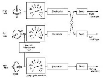
Researchers also concluded that the design would suffer from some level of roll-yaw coupling, and agreed upon acceptable limits. The government also pointed out the need for a rate damping (stability augmentation) system in pitch and yaw for a weight increase of 125 pounds. The need to make the dampers redundant would be the subject of great debate throughout the development phase and early flight program, with the initial decision being not to. Attendees also decided the ballistic control system did not require a damping system, something that would change quickly during the flight program.-122

North American agreed to provide redundant ballistic control systems and to triple the amount of hydrogen peroxide originally proposed. Engineers agreed to provide separate sources of peroxide for the ballistic controls and auxiliary power units (APUs) to ensure that the power units always had propellant. These changes added about 117 pounds.-123

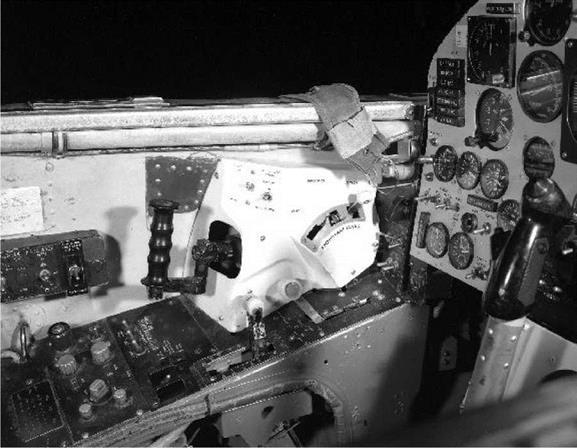
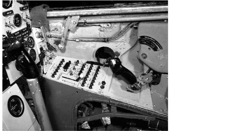
The configuration of the pilot’s controls was finally established. A conventional center stick mechanically linked to a side-controller on the right console operated the aerodynamic control surfaces, while another side-controller on the left console above the throttle operated the ballistic control system. These were among the first applications of a side-stick controller, although these were mechanical devices that bore little resemblance to the electrical side-sticks used in the much later F-16.[24]

In an unusual miscommunication, the attendees at the November meeting believed the WADC had already developed a stable platform and would provide this to North American as government – furnished equipment. Separately, the NACA agreed to supply a "ball nose" to provide angle-of – attack and angle-of-sideslip data. The ball nose, or something functionally similar, was necessary because the normal pitot-static systems would not be reliable at the speeds and altitudes envisioned for the X-15. Although North American proposed a system based on modified Navaho components, the NACA believed that the ball nose represented a better solution.-123

Per a recent service-wide directive, the Air Force representative had assumed that the X-15 would be equipped with some sort of encapsulated ejection system. On the other hand, North American had proposed a rather simple ejection seat. The company agreed to document their rationale for this selection and to provide a seat capable of meaningful ejection throughout most of the expected flight envelope, although all concerned realized that no method offered escape at all speeds and altitudes.-1261

The November meetings ended with a presentation by Douglas engineer Leo Devlin detailing their second-place proposal. A presentation on the advantages of HK31 magnesium alloy for structural use was interesting but provided no compelling reason to switch from Inconel X. Afterwards, Rocketdyne presented a 50,000-lbf rocket engine concept based on the SC-4 being designed for a high-altitude missile; this was a matter of only passing interest, given that a modified XLR30 was already under contract. Separately, Hartley Soule and Harrison Storms discussed the proposed wind-tunnel program, attempting again to agree on which facilities would be used and when.-123

The research instrumentation for the X-15 was the subject of a two-day meeting between personnel from Langley and the HSFS on 16-17 November. The group concluded that strain gauges would be required on the main wing spars for the initial flights, where temperatures would not be extreme, but that wing pressure distributions were not required. The HSFS wanted to record all data in the aircraft, while Langley preferred to telemeter it to the ground. Unfortunately, a lack of funds prevented the development of a high-speed telemetry system. The day following the NACA meeting, representatives from North American drove to the HSFS and participated in a similar meeting. Charlie Feltz, George Owl, and D. K. Warner (North American chief of flight test instrumentation) participated along with Arthur Vogeley, Israel Taback, and Gerald M. Truszynski from the NACA. The participants quickly agreed that the NACA would provide the instruments and North American would install them. The first few flights would use a more or less standard NACA airspeed boom on the nose of the X-15 instead of the yet-to-be-completed ball nose. North American desired to have mockups of the instrumentation within nine months to facilitate the final design of the airplane, and the NACA indicated this should be possible.[28]

The debate regarding engine fuels flared up again briefly at the end of November when John Sloop at Lewis wrote to Captain McCollough recommending the use of a hydrocarbon fuel instead of ammonia. Lewis had concluded that it would be no more difficult to cool a hydrocarbon fuel than ammonia, and the fuel would be cheaper, less toxic, and easier to handle. No information was available on repeated starts of a JP-4-fueled rocket engine, but researchers at Lewis did not expect problems based on recent experience with a horizontally mounted 5,000-lbf engine. The researchers repeated their warning that anhydrous ammonia would attack copper, copper alloys, and silver, all of which were standard materials used in research instrumentation. At the same time, the HSFS wrote that tests exposing a standard NACA test instrument to anhydrous ammonia vapor had proven disastrous. Both NACA facilities repeated their request for a change to a hydrocarbon fuel.[29]

Later the same day, Captain McCollough notified Hartley Soule that the Power Plant Laboratory had reviewed the data submitted by Reaction Motors on the relative merits of substituting a hydrocarbon fuel for ammonia. The laboratory concluded that Reaction Motors had grossly underestimated the development time for conversion, and recommended the continued use of anhydrous ammonia as the most expeditious method of meeting the schedule. A meeting on 1 December at Wright Field brought all of the government representatives together to finalize the fuel issue. The conclusions were that 1) one fuel had no obvious advantage over the other insofar as performance was concerned, 2) the corrosive character of anhydrous ammonia was annoying but tolerable, 3) it would take 6 to 12 months to switch fuels, and 4) the engine development program should continue with anhydrous ammonia. This finally put the issue to rest, although the NACA facilities still believed the requested change was justified.[30]

November also saw an indication that Inconel might have unforeseen problems. A test of the tensile strength of the alloy was published by Langley, and the results differed significantly (in the wrong direction) from the specifications published by the International Nickel Company, the manufacturer of Inconel. NACA Headquarters asked Langley to explain the discrepancies. The reason was unknown, but researchers though it could be related to variations in the material, milling procedures, heat treatment, or testing procedures. Fortunately, further testing revealed that the results from the first test were largely invalid, although researchers never ascertained the specific reasons for the discrepancy. Still, the episode pointed out the need to precisely control the entire life cycle of the alloy.-131

In December, North American engineers visited both Ames and Langley to work out details of the wind-tunnel program. The participants agreed that Langley would perform flutter tests on the speed brakes using the 1/15-scale model. The PARD would make a second flutter investigation, this one of the wing planform, since North American required data from a large-scale model at Mach 5 and a dynamic pressure of 1,500 psf—something no existing tunnel could provide. North American was supplied with additional requirements for a rotary-derivative model to be tested at Ames, and NACA personnel suggested that two 1/50-scale models be constructed—one for testing at Ames and one for Langley. The North American representatives agreed to consider the suggestion, but pointed out that no funds existed for two models. Ames also announced that they would take the 10 by 14-inch hypersonic tunnel out of service on 1 May for several months of modifications. The location was important since the tunnels were not identical and researchers could not directly compare the results from the two facilities.-1321

Ultimately, funds were found to build two 1/50-scale models—one for use at Langley in the 11- inch hypersonic and 9-inch blowdown tunnels, and one for the North American 16-inch wind tunnel. It was decided not to use the Ames tunnel prior to its closing. Langley also tested a 1/15- scale high-speed model while Ames tested a rotary-derivative model. The wind-tunnel investigations included evaluating the speed brakes, horizontal stabilizers, vertical stabilizer, fuselage tunnels, and rolling-tail. Interestingly, the tests at Langley confirmed the need for control system dampers, while North American concluded they were not necessary. This was not the final answer, and researchers would debate the topic several more times before the airplane flew.[33]

CHANGES

Various wind tunnels around the country participated in the X-15 development effort. This 1956 photo shows an original "high tail" configuration. Note the shock waves coming off the wing leading edge and a separate showck wave just behind it coming off the front of the landing skid. Very soon, this configuration would change substantially as the fuselage tunnels were made shorter, the vertical surfaces reconfigured, and the skids moved further aft. (NASA)

North American had based its design surface temperatures on achieving laminar flow during most of the flight profile. However, most of the heat-transfer theories in general use at the time assumed fully turbulent flow on the fuselage. Researchers had previously raised the same issue with no particular solution. Ultimately, researchers used the Unitary Plan tunnel at Langley and the Air Force Arnold Engineering Development Center at Tullahoma, Tennessee, to resolve the discrepancy. These tests provided heat-transfer coefficients that were even higher than the theoretical values, particularly on the lower surface of the fuselage. Because of these results, the Air Force directed North American to modify the design to withstand the higher temperatures.

This proved particularly costly in terms of weight and performance, adding almost 2,000 pounds of additional heat-sink material to the airframe. This is when the program changed its advertising. Instead of using 6,600 fps (Mach 6.5) as a design goal, the program began talking about Mach 6; it was obvious to the engineers that the airplane would likely not attain the original goal. Later, measurements from the flight program indicated that the skin temperatures of the primary structural areas of the fuselage, main wing box, and tail surfaces were actually several hundred degrees lower than the values predicted by the modified theory; in fact, they were below predictions using the original theories. However, resolving these types of uncertainties was part of the rationale for the X-15 program in the first place.[34]

By January 1956, North American required government guidance on several issues. A meeting on 18 January approved the use of a removable equipment rack in the instrument compartment.

North American would still permanently mount some instrumentation and other equipment in the fuselage tunnels, but everybody agreed that a removable rack would reduce the exposure of the majority of research instruments and data recorders to ammonia fumes during maintenance.135

It soon became evident, contrary to statements at the November meeting, that no suitable stable platform existed, although the WADC had several units under development. It was a major blow, with no readily apparent solution.-1361

Other topics discussed at the 18 January meeting included the speed brake design and operation. Full extension of the speed brakes at pressures of 2,500 psf would create excessive longitudinal accelerations, so North American revised the speed brakes to open progressively while maintaining 1,500-psf pressure until they reached the full-open position. All in attendance thought that this was an appropriate solution.-1371

Pilot escape systems came up again during a 2-3 May 1956 meeting at Wright Field among Air Force, NACA, Navy, and North American personnel. WADC personnel pointed to a recent Air Force policy directive that required an encapsulated escape system in all new aircraft. Researchers from the WADC argued that providing some sort of enclosed system would comply with this policy and allow the gathering of research data on such systems. (This seemed an odd rationale in that it appeared to assume that the pilot would use the capsule at some point—an entirely undesirable possibility.) Those opposed to the Air Force view objected to any change because it would add weight and delay development. The opposing group, including Scott Crossfield, believed that the safety features incorporated in the X-15 made the ejection seat acceptable. After the meeting, the Air Force directed North American to justify its use of an ejection seat, but did not direct the company to incorporate a capsule.138

During a 24 May meeting at Langley, representatives from Eclipse-Pioneer briefed researchers from the NACA, North American, and the WADC on a stable platform that weighed 65 pounds and could be ready in 24 months. Later events would show that these estimates were hopelessly optimistic.-1391

On 11 June 1956, the government approved a production go-ahead for the three X-15 airframes, although North American did not cut metal for the first aircraft until September. Four days later, on 15 June 1956, the Air Force assigned three serial numbers (56-6670 through 56-6672) to the X-15 program. The Contract Reporting and Bailment Branch furnished this data by phone on 28 May and confirmed it in writing on 15 June.1401

THE TR-139

The TR-139 engine proposed by Reaction Motors was an extensively modified version of the Navy-developed XLR30-RM-2. Reaction Motors liked to call it a "turborocket" engine because it used turbopumps to supply its propellants, a relatively new concept. The XLR30 dated back to 1946 when Reaction Motors initiated the development of a 5,000-lbf engine to prove the then – new concepts of high-pressure combustion, spaghetti-tube construction, and turbine drive using main combustion propellants. By 1950, engineers believed these principles were sufficiently well established to initiate the development of a 50,000-lbf engine. The turbopump and its associated valves completed approximately 150 tests, and Reaction Motors considered it fully developed, with the exception of additional malfunction-detection and environmental tests that were required before a flight-approval test could be undertaken. The evaluation of a "breadboard" engine had demonstrated safe and smooth thrust-chamber starting, achieved 93-94% of the theoretical specific impulse, and shown satisfactory characteristics using film cooling.-126

The engine consisted of a single thrust chamber and a turbopump to supply the liquid oxygen and liquid anhydrous ammonia propellants from low-pressure tanks on the aircraft. These propellants had boiling points of -298°F and -28°F, respectively. That meant that after the propellants were loaded into the X-15 tanks, they would immediately begin to boil off at rates that were dependent upon the nature of the tank design and ambient conditions. In an uninsulated tank, liquid oxygen has a boil-off rate of approximately 10% per hour on a standard day. Even the crudest insulation significantly lowers this, and a well-insulated tank can experience less than 0.5% per hour of boil- off. Reaction Motors pointed out that insulating a tank usually required a great deal of volume, and that the airframe manufacturer would need to conduct a trade study to find the best compromise between volume and boil-off. Since the B-36 carrier aircraft had sufficient volume to carry additional liquid oxygen to top off the X-15, this was not a major issue. Anhydrous ammonia, on the other hand, has a relatively high boiling point and very low evaporation losses. Simply sealing the tank by closing the vent valve would minimize losses to the point that the ammonia would not have to be topped off before launch.-127

Reaction Motors did have some cautions regarding the hydrogen peroxide that powered the TR – 139 turbopump and the X-15 ballistic control system. It was necessary to maintain the propellant below 165°F to prevent it from decomposing, and Reaction Motors believed that it would be necessary to insulate all the valves, lines, and tanks. North American thought that only the main storage tank required insulation, because of the relatively short exposure to high temperatures. However, not insulating the entire system allowed small quantities of propellant (such as found in the lines supplying the reaction control system) to potentially reach elevated temperatures. To counter this, Reaction Motors recommended installing a continuous-circulation system whereby the propellant was kept moving through the lines in order to minimize its exposure to high compartment temperatures, particularly in the wings. If the engineers found the circulation system to be insufficient, it was possible to install a rudimentary cooling system on the main tank.-1281

THE TR-13920 40 ЄО 80 100 а ALTITUDE X 1000 FT.

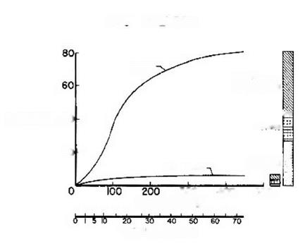
ENGINE THRUST ENVELOPE

The final Reaction Motors contract called for an engine capable of being throttled between 15,000 Ibf and 50,000 lbf, although this was later raised to 57,000 lbf. Some engines actually produced more than 60,000 lbf. The engine needed to operate for 90 seconds at full power or 249 seconds at 15,000 lbf. (NASA)

Engineers considered the TR-139 thrust chamber very lightweight at 180 pounds. Furthermore, it used an assembly of "spaghetti tubes" as segments of the complete chamber, and, as it turned out, the spaghetti tubes would prove to be one of the more elusive items during engine development. The thrust chamber used ammonia as a regenerative coolant, but the exhaust nozzle was uncooled and configured to optimize thrust at high altitude. Reaction Motors expected to use a slightly altered XLR30 thrust chamber. The modifications included the incorporation of a liquid propellant igniter (for restarts) and derating to operate at 600 psia instead of 835 psia. The lower chamber pressure was desired to improve local cooling conditions at low thrust levels.-129

In order to improve safety, Reaction Motors proposed the simplest igniter the engineers could think of. The igniter was located along the centerline at the top of the chamber and had two sections. The first section contained a catalyst bed that used activated silver screens to decompose hydrogen peroxide into steam and oxygen at 1,360°F. The second section consisted of a ring of orifices where fuel was injected; when the fuel and superheated oxygen mixed, they combusted. The resulting flame was used to ignite the propellants in the combustion chamber. Reaction Motors believed this simple igniter would not be subject to the kind of failures that could

occur in electrical ignition systems. Despite the apparent desirability of this arrangement, a more traditional electrical ignition system was used in the final engine.[30]

The XLR30 turbopump was a two-stage, impulse-type turbine driving fuel and oxidizer pumps. The turbine operated at a backpressure of 45 psia at full thrust. The designers matched the pump characteristics to allow varying engine thrust over a wide range of thrust simply by varying the power input to the turbine. Varying the flow of hydrogen peroxide to a gas generator controlled the speed of the turbine. The gas generator consisted of a simple catalyst bed that decomposed the hydrogen peroxide into steam. Reaction Motors expected that the engine would need only 2.5 seconds to go from ignition to maximum thrust, and only 1 second to go from minimum to maximum thrust. On the other side, it would take about 1 second to go from maximum to minimum thrust, and not much more to complete a shutdown.-131

However, using a single turbine to drive both the fuel and oxidizer pumps resulted in the XLR30 liquid-oxygen pump operating at too high a speed for the new XLR99. Haakon Pederson, who became the principal designer of the XLR99 turbopumps, modified the original XLR30 oxidizer pump section to have a single axial inlet impeller operating in conjunction with a directly driven cavitating inducer. This required a new impeller design, new casting patterns, a new inducer, and a new pump case. Essentially, this was a new liquid-oxygen pump, and it became one of the major new developments necessary for the XLR99.-132

At this point, Reaction Motors expected to take 24 months to develop the new engine, followed by six months of testing and validation. The company would deliver the first two production engines in the 30th month, and manufacture 10 additional engines at a rate of one per month.-133

All parties finally signed the Reaction Motors contract on 7 September 1956, specifying that the first flight-rated engine was to be ready for installation two years later. The Air Force called the "propulsion subsystem" Project 3116 and carried it on the books separately from the Project 1226 airframe. The final $10,160,030 contract authorized a fee of $614,000 and required that Reaction Motors deliver one engine and a mockup, as well as various reports, drawings, and tools. The 50,000-lbf engine would be throttleable between 30% to 100% of maximum output. The 588- pound engine had to operate for 90 seconds at full power or 249 seconds at 30% thrust.-134

Less than two months after the Air Force issued the letter contract, the NACA began to question the conduct of Reaction Motors. On 11 April 1956, John Sloop from Lewis visited the Reaction Motors facilities and reported a multitude of potential development problems with the ignition system, structural temperatures, and cooling. Sloop reported that approximately 12 engineers were working on the engine, and that Reaction Motors expected to assemble the first complete engine in May 1957. However, Sloop believed that the Reaction Motors effort was inadequate and questioned whether the appropriate test stands at Lake Denmark would be available in late 1956. Sloop suggested that the company needed to assign more resources to the XLR99 development effort.-133

Despite the issues raised by Sloop, the Air Force did not seem to be concerned until 1 August 1956, when the Power Plant Laboratory inquired why scheduled tests of the thrust chamber had not taken place. It was not explained why four months had elapsed before the Air Force questioned the schedule slip.-133
important for maintaining the schedule. Reaction Motors also attributed part of the delay to modifications of two available test chambers to accommodate the high-powered engine.[37]

Fixed-Base Simulators

Simulation in the X-15 program meant much more than pilot training. It was perhaps the first program in which simulators played a major role in the development of an aircraft and its flight profiles. The flight planners used the simulators to determine heating loads, assess the effects of proposed technical changes, abort scenarios, and perform a host of related tasks. In this regard, the term "flight planner" at the AFFTC and FRC encompassed a great deal more than someone who sat down and wrote out a plan for a launch lake and a landing site. It is very possible that the flight planners (such as Elmore J. Adkins, Paul L. Chenoweth, Richard E. Day, Jack L. Kolf, John A. Manke, and Warren S. Wilson at the FRC, and Robert G. Hoey and Johnny G. Armstrong at the AFFTC) knew as much as (or more than) the pilots and flight-test engineers about the airplanes.-12!

The initial group of X-15 pilots worked jointly with research engineers and flight planners to

develop simulations to study the aspects of flight believed to present the largest number of potential difficulties. During late 1956, North American developed a fixed-base X-15 simulator at their Inglewood facility that consisted of an X-15 cockpit and an "iron bird" that included production components such as cables, push rods, bellcranks, and hydraulics. The iron bird looked more or less like an X-15 and used flight-representative electrical wiring and hydraulic tubing, but otherwise did not much resemble an aircraft. The simulator included a complete stability augmentation system (dampers), and ultimately added an MH-96 adaptive flight control system. Controlling the simulator were three Electronics Associates, Inc. (EAI) PACE 231R analog computers that contained 380 operational amplifiers, 101 function generators, 32 servo amplifiers, and 5 electronic multipliers. None of the existing digital systems were capable of performing the computations in real time, hence the selection of analog computers. The simulator could also compute a real-time solution for temperature at any one of numerous points on the fuselage and wing. Simulations were initiated in October 1956 using five degrees of freedom, and the simulator was expanded to six degrees of freedom (yaw, pitch, roll, and accelerations vertically, longitudinally, and radially) in May 1957.[3]

X-15 FLIGHT SIMULATION

Fixed-Base Simulators

Simulation in the X-15 program meant much more than pilot training and was the first program where simulators played a major role in the development of the aircraft and its flight profiles. Engineers used the simulators to determine heating loads, the effects of proposed technical changes, and to develop abort scenarios. Controlling the simulator were three Electronics Associates, Inc. (EAI) PACE 231R analog computers that contained 380 operational amplifiers, 101 function generators, 32 servo amplifiers, and 5 electronic multipliers. None of the existing digital systems was capable of performing the computations in real time, hence the selection of analog computers. (NASA)

The simulator covered Mach numbers from 0.2 to 7.0 at altitudes from sea level to 1,056,000 feet (200 miles), although it was not capable of providing meaningful landing simulations. The initial round of simulations at Inglewood showed that the X-15 could reenter from altitudes as high as 550,000 feet as long as everything went well. If done exactly right, a reentry from this altitude would almost simultaneously touch the maximum acceleration limit, the maximum dynamic pressure limit, and the maximum temperature limit. The slightest error in piloting technique would exceed one of these, probably resulting in the loss of the airplane and pilot. An angle of attack of 30 degrees would be required with the speed brakes closed, or only 18 degrees with the speed brakes open. The normal load factor reentering from 550,000 feet would reach 7 g, and a longitudinal deceleration of 4 g would last up to 25 seconds. Simulations in the centrifuge confirmed that pilots could maintain adequate control during these maneuvers, and considerations for the physical well-being of the pilot did not limit the flight envelope.-^

These first simulations indicated the need for a more symmetrical tail to reduce aerodynamic coupling tendencies at low angles of attack, and potential thrust misalignment at high velocities and altitudes. This resulted in the change from the vertical-stabilizer configuration proposed by North American to the one that was actually built. Reentry studies indicated that the original rate – feedback-damper configuration was not adequate for the new symmetrical tail, and an additional feedback of yaw-rate-to-roll-control (called "yar") was required for stability at high angles of attack.-51

Initially, the North American fixed-base simulator was computation-limited, and researchers could only study one flight condition at a time. The first three areas investigated were the exit phase, ballistic control, and reentry. Later, upgrades allowed complete freedom over a limited portion of a mission, and by mid-1957 unlimited freedom over the complete flight regime. By July 1958, the fixed-base simulator at North American already had over 2,000 simulated flights and more than 3,500 hours of experience under various flight conditions, and the airplane would not fly for another year.

As crude as it may seem today, the simulator nevertheless provided the flight planners with an excellent tool. The flight planner first established a detailed set of maneuvers that resulted in the desired test conditions. He then programmed a series of test maneuvers commensurate with the flight time available to ensure that the maximum amount of research data was obtained. Since the simulator provided a continuous real-time simulation of the X-15, it enabled the pilot to fly the planned mission as he would the actual flight, allowing him to evaluate the planned mission from a piloting perspective and to recommend changes as appropriate. Certain data, such as heating rates and dynamic pressures, required real-time computations to verify that the desired maneuvers were within the capability of the airplane.-61

Fixed-Base Simulators

The fixed-base simulator at North American was hardly a fancy affair, just a mocked-up cockpit with a full set of instruments and a television screen. The original cadre of pilots, including Joseph A. Walker, spent a considerable amount of time in the North American simulator before the one at the Flight Research Center was ready. Although crude by today’s standards, the X-15 pioneered the use of simulators not just to train pilots, but also to engineer the aircraft, plan the missions, and understand the results. Not surprisingly, given the involvement of Charlie Feitz, Harrison Storms, and Walt Williams in both the X-15 and Apollo programs, the X-15 pointed the way to how America would conduct its space missions. (NASA)

Engineers also used the simulator to develop vehicle systems before committing them in flight. One of the most notable was the MH-96 adaptive flight control system. Exhaustive tests in the simulator, conducted largely by Neil Armstrong, allowed researchers to optimize system parameters and develop operational techniques. Similarly, engineers used the simulators to investigate problems associated with the use of the dampers, and devised modifications to install on the airplane. Researchers then incorporated the results of flight tests into the simulator.-171

(excepting the computers) to the FRC before turning the first airplane over to the government. Unlike the Inglewood installation, at the FRC the cockpit and analog computers were in the same room: not much to look at, but functional. The Air Vehicle Flight Simulation Facility was located in building 4800 at the FRC in an area that later became the center director’s office. Like many early computer rooms, it used a linoleum-covered plywood false floor to cover the myriad of cables running beneath it. Large air conditioners installed on the building roof kept the computers cool. The X-15 simulator used a set of EAI analog computers procured for earlier simulations at the FRC, including one model 31R, one 131R, and one 231R that were generally similar to the computers used by North American. John P. Smith had begun mechanizing the original equations in the simulator, but Gene L. Waltman completed the task during the last three months of 1960 after Smith was promoted to a new job. The X-15 simulator became operational at the FRC on 3 January 1961. The X-15 simulator was the largest analog simulation ever mechanized at the FRC. The initial Air Vehicle Flight Simulation Facility at the FRC cost $63,000 and upgrades accounted for a further $1,700,000 by the end of 1968.-8

Because the FRC simulator was not yet operational, the flight planning for the first 20 flights used the North American simulator. Dick Day and Bob Hoey spent a considerable amount of time during 1959 and 1960 in Inglewood on flight planning and training the first cadre of pilots.-9 Initially, North American was to transfer the simulator from Inglewood to the FRC in January 1961, but the move was delayed for various reasons, including the need to integrate the MH-96 adaptive flight control system into X-15-3. By March 1961, however, Paul Bikle was becoming concerned: "With the performance envelope expansion program now underway, the requirement of traveling to NAA [North American Aviation] to use the X-15 simulator is becoming unduly restrictive in time and in obtaining the close working relationships essential to a sound flight panning effort." Something needed to change.-10

Bikle knew that North American did not want to transfer the simulator until the MH-96 integration was complete. In an effort to determine the consequences of moving earlier, Bikle called Dave Mellon at Minneapolis-Honeywell, who said he did not think the move would have an adverse affect on his schedule. Bikle also commented that "if a program delay is inevitable, it is preferable to delay the X-15-3 rather than the present program with the X-15-2." Bikle pushed to have the simulator moved to the FRC during April 1961. "We again want to emphasize that once the transfer has been accomplished, the NASA will make the simulator available for whatever additional simulator effort is required by NAA, M-H [Minneapolis-Honeywell], and other contractors…."-19

Fixed-Base Simulators

At first, the Flight Research Center made do with the crude cockpit that had been used in the centrifuge at NADCJohnsville. This was a cost-saving measure since the X-15 contract required North American to deliver their simulator (excepting the computers) to the FRC before turning the first airplane over to the government. Unlike the Inglewood installation, the cockpit and analog computers were in the same room at the FRC. The Air Vehicle Flight Simulation Facility was located in Building 4800 at the FRC in an area that later became the center director’s office. (NASA)

When the iron bird finally arrived in April 1961, engineers installed it along the east wall of the calibration hangar next door to the computer facility. A wall around the simulator provided some separation from the operations in the hangar. The cockpit faced away from the hangar door, and pilots discovered that sunlight coming through the windows caused visibility issues, so paint soon covered the windows. One of the unfortunate aspects of this installation was that the iron bird was located a little over 200 feet from the computers. This caused a number of signal-conditioning problems that a better grounding system eventually corrected. The hydraulic stand for the iron bird was originally located next to the mockup inside the hangar, but technicians subsequently relocated the unit to a small shed just outside, eliminating most of the noise from the simulator laboratory.-1121

To provide simulations that were more realistic, engineers at the FRC added a "malfunction generator" that could simulate the failure of 11 different cockpit instruments and 23 different aircraft systems. The instruments included a pressure altimeter, all three attitude indicators, and pressure airspeed, dynamic pressure, angle-of-attack, angle-of-sideslip, inertial altitude, inertial velocity, and inertial rate-of-climb indicators. The vehicle systems that could be failed included the engine, ballistic control system, both electrical generators, and any axis in the damper system. Later, the simulator could duplicate the failure of almost any function of the MH-96 adaptive control system. Almost all X-15 flights were preceded by practicing various emergency

procedures in the simulator using these malfunction generators.-1131

Fixed-Base Simulators

The final simulator at the Flight Research Center was functionally identical to the one at North American, and used the same analog computers. The structure behind the cockpit is the "iron bird" that included production components such as cables, push rods, bellcranks, and hydraulics. The iron bird looked more or less like an X-15 and used flight-representative electrical wiring and hydraulic tubing, but otherwise did not much resemble an aircraft. The simulator included a complete stability augmentation system (dampers), and ultimately added an MH-96 adaptive flight control system. (NASA)

Contrary to many depictions of flight simulators in movies, the fixed-base simulator for the X-15 was not glamorous. The iron bird stretched behind the cockpit, but other than in size, it did not resemble an X-15 at all. The cockpit was open, and the sides of the "fuselage" extended only high enough to cover the side consoles and other controls inside of it. A canopy over the cockpit became necessary when researchers installed some instruments and controls (particularly for the experiments) there for later flights, but even then, it was made of plywood.-141

However, unlike most of the previous simulators at the FRC, the X-15 cockpit did have an accurate instrument panel. On one occasion, technicians inadvertently switched the location of the on/off switches for the ballistic control system and the APUs between the simulator and the airplane. It was normal procedure for the pilot to turn off the ballistic controls after reentry, and he practiced this in the simulator before each flight. During the actual flight, the pilot reached for the APU switch instead of the switch he thought was there. Fortunately, he caught himself and avoided an emergency. Everybody redoubled their efforts to ensure that the simulator accurately reflected the configuration of the airplane.15

When X-15-3 came on line with a completely different instrument panel arrangement, it presented some challenges for the simulator. Since the pilots needed to train on the correct instrument panel layout, the simulator support personnel had to swap out instrument panels to accommodate each different airplane. The technicians eventually installed a crank and pulley lift in the ceiling, along with cannon plugs for the electrical connections, to assist in making the change. On at least three occasions the program decided to make the instrument panels in the three airplanes as similar as possible, but they quickly diverged again as new experiments were added.1161

In addition to its simulation tasks, the iron bird found another use as the flight program began. Engineers and technicians at the FRC soon discovered that it was a relatively simple task to remove troublesome components from the flight vehicles and install them on the iron bird in an attempt to duplicate reported problems. Given the initial lack of test equipment available for the stability augmentation system and some MH-96 components, this proved a useful troubleshooting method. The simulator also played an important role in demonstrating the need for advanced display and guidance devices, and found extensive use in the design and development of new systems.-1171

The simulator had a variety of output devices in addition to the cockpit displays, including several eight-channel stripchart recorders and a large X/Y flatbed plotter. The plotter had two independent pens: one showed the X-15 position on a 3-foot-square map of the area, and the other indicated altitude. This plotter was identical to ones used in the control room and at the uprange stations. There were different maps for each launch lake showing the various contingency landing sites and prominent landmarks.1181

Eventually the FRC simulator grew to encompass six analog computers, and the patch panels needed to operate them contained 500 patch cords. The addition of a Scientific Data Systems SDS-930 digital computer in 1964 allowed the generation of nonlinear coefficients for the X – 15A-2. This required an additional analog computer as an interface between the new digital computer and the rest of the simulator. The SDS-930 was somewhat unusual in that it was a true real-time computer, complete with a real-time operating system and a real-time implementation of Fortran.1191

Despite its advanced specifications the SDS-930 was not initially satisfactory, which forced the flight planners to use the modified Dyna-Soar hybrid simulator at the AFFTC for the early X-15A – 2 flights. The SDS-930 was generally unreliable, normally because of memory-parity errors that the computer manufacturer attempted to fix on numerous occasions during 1965, with little success. The problem was not only affecting flight planning for the X-15A-2, it was also delaying simulations needed for the energy-management system scheduled to fly on X-15-3. During early 1966, the SDS-930 was extensively modified to bring it up to the latest configuration, including the addition of two magnetic-tape units and a line printer to assist in the energy-management simulations. While this was going on, the FRC took advantage of the downtime to upgrade the SAS and ASAS implementation on the iron bird, including replacing all of the computer interface equipment for both systems. Technicians also brought all of the mechanical rigging up to the same standard as the three airplanes. However, Johnny Armstrong and Bill Dana both recall that no actual flight planning or flight simulation was "totally digital."1201

The hybrid (analog-digital) simulator at the AFFTC initially provided a tool that enabled studies of the performance and handling of the X-20 glider, complete mission planning, and pilot familiarization. It was a logical outgrowth of the analog fixed-base simulators for the X-15. Although they had been ordered long before, the digital computers did not arrive at Edwards until

July 1964, six months after the cancellation of the Dyna-Soar program. The equipment sat mostly unused until the flight planners decided to adapt it to the X-15A-2 Mach 8 flight expansion program. This was done as much to provide Air Force personnel with some hands-on experience as for any demonstrated need for another X-15 simulator.-1211

The analog section of the hybrid simulator used PACE 231R-V and 231R computers similar to those used at the FRC and North American installations. Each computer had approximately 75 operational amplifiers, 170 potentiometers, 36 digitally controlled analog switches, and 26 comparators, and the 231R-V had a mode-logic group that supported an interface to a digital computer. The digital subsystem used a Control Data Corporation DDP-24 that had 8,192 words of ferrite core memory, a 5-microsecond access time, and a 1-MHz clock. Although a Fortran II compiler was available on the machine, engineers coded the real-time programs in assembly language to maximize the performance of the relatively slow machines. Two large patch panels connected the analog subsystem and digital subsystem.-1221

Fixed-Base Simulators

The fixed-base simulators at Inglewood and the FRC consisted of four major parts. The simulator included both controls and displays that were nearly identical to what the pilot found in the X-15 cockpit. The analog computer and malfunction generator were the heart of the system that provided the sequencing and control of the other components. The hydraulic control system was the "iron bird" and actually contained other flight components in addition to the hydraulic system including a complete stability augmentation system (or, later, a complete MH-96 adaptive flight control system). (NASA)

Like the other fixed-base simulators, the AFFTC device had a functional X-15 instrument panel, although it was not as exact as the ones used at the FRC. This was because its intended use was to investigate heating and control problems related to the X-15A-2, not to conduct pilot training. Ultimately, the program did use the AFFTC simulator for some X-15A-2 pilot training, but the final "procedures" training was conducted at the FRC.

Since the X-15 program technically did not need the simulator, the AFFTC engineers were able to develop a "generic" simulation that was usable for other aircraft, not just the X-15. This was an extremely astute idea, and the engineers subsequently used the simulator for the M2-F2, SR-71, X-24A, X-24B, and EF-111. The hybrid simulator was also the only one available to perform heating predictions during reentry simulations of the Space Shuttle Orbiter during the early 1970s, providing valuable input to that program.-123

At the FRC, the simulation team kept busy maintaining the computers and updating the programming to reflect actual flight results. During most of the flight program the simulation lab was busy for at least two shifts, and often three shifts, per day. The first shift performed pilot training and flight planning, the second shift conducted control-system and other studies, and maintenance and reprogramming occupied the third shift as needed. However, the team generally took weekends off. This was not necessarily a good thing for the simulator since it took the analog computers quite a while on Monday morning to warm up.-123

Despite the apparent success of the fixed-base simulators, everybody recognized their limitations. The primary concern was that they were fixed-base and not motion-base, and therefore were inappropriate for landing training. For instance, the lack of a high-quality visual presentation meant that critical visual cues were not available to the pilots. The analog computer also had limitations. For example, the precision needed to calculate altitude and rate of climb for the landing phase was not readily achievable with the parameter scaling used for the rest of the flight. The parameter scaling was critical, and analog computers were accurate to about one part in 10,000. For the X-15 simulation, with the altitude scaled such that 400,000 feet equaled 100 volts, one-tenth of a volt was equal to 40 feet. Any altitude less than this was down in the noise of the analog components and barely detectable. It was simply not possible to calculate accurate altitudes for the landing phase and the rest of the flight profile at the same time. All of this necessitated maintaining a fleet of Lockheed F-104 Starfighters as landing trainers, something the X-15 pilots did not seem to mind at all.-123

Nevertheless, Larry Caw and Eldon Kordes did mechanize a simple four-degrees-of-freedom simulation to study landing loads early in the program. The simulation only covered the last few seconds of a flight, and was not particularly useful as a pilot training tool. However, it allowed Jack McKay and other engineers to look at the variety of forces generated during an X-15 landing, and prompted the first round of landing-gear changes on the airplane.-126

The lack of a motion-base simulator presented several interesting problems. For instance, some phenomena experienced in the JF-100C variable-stability airplane during the summer of 1961 indicated that using the beta-dot technique in the X-15 might be more difficult than anticipated. Consequently, a cooperative program was initiated with NASA Ames to use its three-axis motion – base simulator. The objective was to investigate further the effect of g-loading on the pilot while he performed beta-dot recovery maneuvers. Four pilots-Forest Petersen, Bob Rushworth, Joe

Walker, and Bob White-participated in the tests during September 1961. Paul Bikle reported that, "With fixed-base simulation, the ventral-on condition was uncontrollable, using normal techniques; however, it could be controlled by using the special beta-dot control technique. With the moving cockpit simulation, control using either normal or beta-dot techniques was more difficult for the pilot than with the fixed-base cockpit simulation. These results were in general agreement with the ground and flight tests conducted with the variable-stability F-100 airplane."271

By the end of the X-15 program, the FRC had established simulation as an integral part of the flight program. Today, the Walter C. Williams Research Aircraft Integration Facility (RAIF) provides a state-of-the-art complex of computers, simulators, and iron-bird mockups. As an example of the extent to which simulations were used, during the X-33 program, pilot Stephen D. Ishmael flew countless missions while engineers evaluated vehicle systems, flight profiles, and abort scenarios. What is ironic is that the X-33 was to be an unmanned vehicle— Ishmael was just another computing device, one with a quick sense of reason and excellent reflexes.