Category And Colors

. 2. AUTHORIZED FINISHES

a. DAY CAMOUFLAGE. – Standard day camouflage for liaison aircraft, helicopters, and gliders consists of upper surfaces olive drab, shade No, 41, Bulletin 41 or AN Bulletin 613; and lower surfaces neutral gray, shade No. 43, Bulletin 41 or Army-Navy sea gray, No. 603. (See AN Bulletin 157A.)

b. NIGHT CAMOUFLAGE.

(1) GENERAL. – Special black camouflage paints, color designation, “Jet No. 622,” have been developed for use in minimizing visibility of airplanes at night. The estimated quantities of materials required will be found in table 1.

(2) PREPARATION OF SURFACES.

(a) Metal surfaces which are painted with dull camouflage finish should preferably be stripped to bare metal in accordance with T. O. No. 07-1-7, and the metal cleaned and primed in order to save weight. However, if weight is not critical, Jet No. 622 camouflage enamel may be applied directly over the dull finish, after thorough cleaning and careful smoothing with No. 320 or finer waterproof sandpaper and water to minimize porosity and roughness.

NOTE Application of lacquer over enamel may cause lifting of the enamel. If, upon trial, trouble is encountered in application of lacquer over the old finish, the finish must be removed or Jet No. 622 enamel used. Prior to application of Jet No. 622 camouflaged enamel, unpaintcd metal surfaces will be cleaned in accordance with Specification No. 98-20007 (or phosphoric acid alcohol cleaner in accordance with T, O. No. 01-1-1) and then primed with one smooth coat of zinc chromate primer, Specification No. AN-TT-P-656.

(b) Wood surfaces painted with dull camouflage or aluminized finish will be cleaned and then smoothed out by sanding with No. 320 or finer waterproof sandpaper and water, prior to application of the Jet No. 622 camouflage enamel. Unfinished wood sur faces will be prepared in accordance with Specification No. AN-C – 83, to produce a surface as smooth and free from irregulari­ties as possible, prior to application of the Jet No. 622 camouflage enamel. Surfacer, Specification No. 14116, may be used in direct-on-wood finishes, provided the film is sanded as thin as possible commensurate with the desired smoothness and “hold­out” or fullness of gloss of the final finish.

TABLE 1

METAL SURFACES FABRIC SURFACES

Lacquer, Specification

or Enamel, Specification

Dope, Specification

Total Approx.

No. AN-TT-L-51

No. AN-E-3

No. AN-TT-D-554

Weight Increase

Fighter (P-40) 10 gal

or 6 gal

2 gal

15 lb

Bomber (B-24) 30 gal

or 15 gal

7 gal

46 lb

Requirements for other airplanes may be estimated from the preceding table.

image308

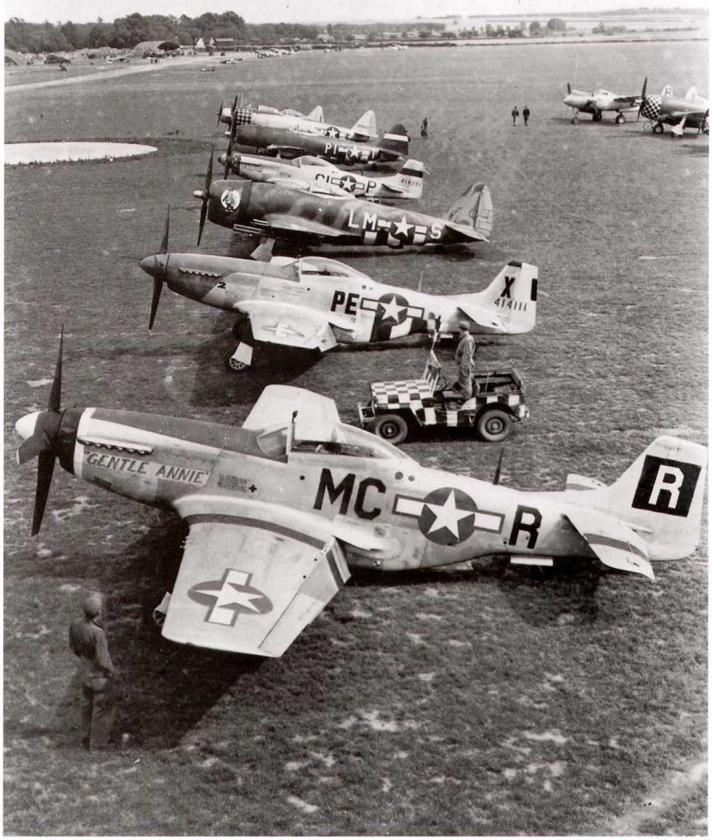
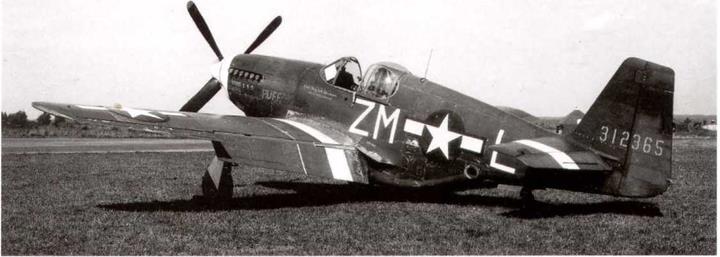
North American P-51D-5-NA, 44-13550, aircraft A9-M of the 380th FS, 363rd FG, seen at strip A-8 on August 10,1944. Note how the invasion stripes have been painted out above the top of the fuselage and insignia, with dark olive drab. The same was dune to the stripes above the wings. Squadron color on the spinner is blue. (William L. Swisher)

(3) APPLICATION. – Application of Jet No. 622 camouflage will be by spraying, which presents no unusual problems. How­ever, because of the need to produce a black finish having as near mirror-like an appearance as possible, it is necessary to take extra precautions to avoid dust during painting and drying. Dust which becomes adhered to the paint, especially on the bottom and side surfaces, will result in reduced effectiveness of the camouflage.

NOTE Lacquer, being faster drying, is preferred for Jet No. 622 finish for this reason.

image309

Lockheed P-38H-5-LO, 42-66923; P-51A-10-NA, 43-6246: and P-47D-23-RA, 42-27798, From the AAF School of Applied Tactics, at Orlando Army Air Base, FI. Note the white ellipse markings of the school aircraft on the nose. The last three digits of the serial number were painted black on the ellipse. The school was under control of the AAF Board, who reported to the Dir. of Mil. Req. in Washington. (USAF via Gerry R. Markgraf)

image310

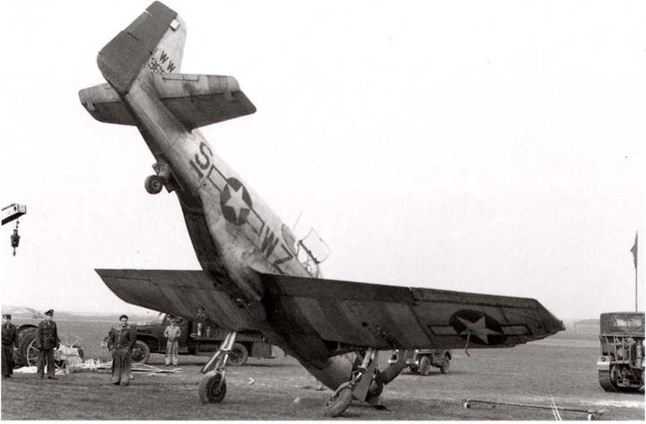
Republic P-47D-21-RA, 43-25572, aircraft YJ-N “Smoocher”, of the 351st FS, 353rd FG, Eighth Air Force, with heavy wing damage sustained in a belly landing. Nose cowl is in black and yellow checks. Code letters are in white. Invasion stripes underneath only. August 13,1944, (USAF)

Jet No. 622 lacquer will be applied to the properly prepared surfaces of metal {and wood) by spraying not less than two full coats; Jet No. 622 enamel, one mist coat and one hiding coat. Application of the camouflage material will be controlled so as to produce a finish of uniform hiding and blackness and very high gloss.

NOTE In the event that a rough finish is applied in the field, it may be smoothed by rubbing lightly with 320 or 400 waterproof abrasive paper after which a light, but wet, coat of camouflage material should be applied,

(4) FABRIC SURFACES. – Fabric doped with dull camouflage finish which has not become brittle, may be converted to jet camouflage by the following procedure: Remove all grease and dirt, then wash with soft soap and water, rinse with clean water, and allow the surfaces to dry. Apply two wet spray coats of thinner, Specification No, AN-TT-T-256, to soften up the old finish, and allow to dry not more than 30 minutes. Apply three spray coats of gloss black pigmented dope, the last of which is cut with an equal portion of clear dope, Specification No. AN-TT-D-514, before thinning to impart added gloss. If fabric is new, dope in accordance with Specification No. 98-24100, using a minimum of two brush and two spray coats of AN-TT-D-514 dope. Follow with one spray coat of sanding guide dope (3 ounce pigment, aluminum per gallon of AN-TT-D-514 dope). Sand (dry) moderately with No. 280 (or finer) sandpaper to minimize weave effects.

NOTE Ground parts when sanding.

Finish with three spray coats of gloss black pigmented dope, Specification No. AN-TT-D-554, the last coat of which is cut with an equal portion of (clear), Specification No. AN-TT-D-514 dope, before thinning, to impart added gloss.

(5) MAINTENANCE OF JET NO. 622 FINISH.

(a) The effectiveness of night camouflage is reduced by accumulations of mud, dust, oil, gun blast, or exhaust gas residues, and chalking of the paint film, particularly on sides and under surfaces, of aircraft. Excessively widespread scratches, and es­pecially bare metal exposed by scratches, also have a deleterious effect. Therefore, cleaning and maintenance operations on the airplane should be so conducted as to avoid scratching the finish and to minimize exposure of bare metal. Before engaging in night operation, mud, dust, muzzle blast or exhaust gas residues and oil should be removed and all bare metal areas re-touched with Jet No. 622 camouflage material, especially on sides and under surfaces. At least once a week, and oftener, if necessitated by ground or atmospheric conditions, the airplane shall be washed and then polished with aircraft polish, stock No. 7300755000. The use of wax is discouraged because it will interfere, subsequently, with the drying of paint where retouching is necessary and because satisfactory results are obtainable through the use of polish. THE CLOSER THIS TYPE OF CAMOUFLAGE AP­PROACHES THE APPEARANCE OF A BLACK MIRROR, THE MORE EFFECTIVE IT BECOMES.

(6) REJUVENATION. – If, on extended exposure, a surface haze appears on the paint, which cannot be removed with polish, wash with soap and water and rinse with clean water then wipe surface thoroughly with clean cloths wet with naphtha or solvent, Specification No. P-S-661. The cloths should be wet by pouring solvent on them and should not be dipped into the solvent. Spray one light coat of Jet No. 622 camouflage enamel, Specification No. AN-E-3, or lacquer, Specification No. AN-TT-L-51. Clean doped surfaces in the same manner, but apply only glossblack dope, Specification No. AN-TT-D-554, cut with clear dope, Specification No. AN-TT-D-514.

C A U1′ 1 О N DO NOT APPLY LACQUER ON JET 622 ENAMEL, AS IT WILL INJURE ENAMEL FILM. CHECK THF STENCILED MARKING FOR APPLICABLE SPECIFICATION OR TEST WITH LACQUER SOLVENT.

image311

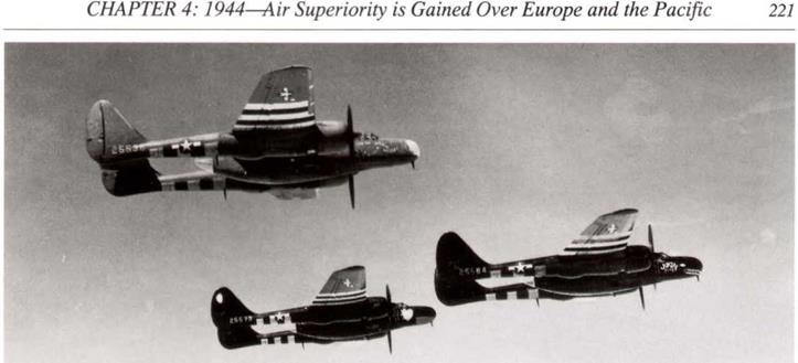
Northrop P-61A-1U-NO, serial unknown, named “Lucky Lady” on the nose and “Doris” on the right hand engine cowl, seen at strip A-8 on August IS, 1944. (William L. Swisher)

image312

Republic P-47D, of the 375th FS, 361st FG, running up at Langley Field, Virginia, in the USA, prior to the unit embarking for Bottisham, England, in July 1943. This was the last P-47 Group to be assigned to the Eighth Air Force. Note the fancy nose cowl red marking with white trim; these markings were not used in England. Serial number not visible. (USAF via Gerry R. Markgraf)

image313
Republic P-47D-25-RE, 42-26418, aircraft HV-A, flown by Lt. Col. Francis Gabreski, of the 61st FS, 56th FG, having its guns rearmed, Note the colors of the gun hay: zinc chromate primer and Dark Olive Drab on the wing rib top faces. Aircraft was painted in dark green and ocean gray, courtesy of the RAF, with front half of the cowl and the rudder in red. Full invasion stripes were above and below this aircraft. Col. Gabreski was shot down over Germany in this aircraft on July 20,1944. (USAF via Gerry R. Markgraf)

image314

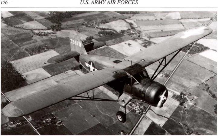
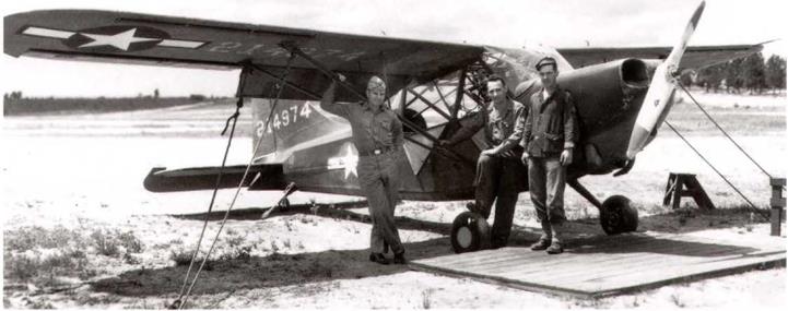
Douglas A-24B-DT, 42-54897, was the third from last A-24 huilt. Seen here in Air Transport Command service in the USA on August 21, 1944. (Nick Williams)

c. METAL CORROSION PREVENTION. – The exterior of alclad metal fuselages and metal airfoils does not ordinarily require paint as a protection against corrosion. (Refer to T. O. No. 01- 1-2.) However, where it is necessary to provide additional pro­tective finish on any parts not made from aluminum coated aluminum alloy, any such unprotected parts will be cleaned with phosphoric acid alcohol cleaner, finished with one coat of zinc chromate primer, Specification No. AN-TT-P-656, and two coats of aluminized lacquer. Aluminized lacquer consists of lacquer, cellulose nitrate, clear, Specification No. AN-TT-L-51, pig­mented with 12 ounces per gallon of paste, aluminum pigment, Specification No. TT-A-468.

d. ANTIGLARE. – Antiglare camouflage olive drab or dull dark green paint is authorized where necessary, to be applied to top of the fuselage in front of the cockpit and on the inside upper one-fourth of the engine nacelle forward of the leading edge of the wing.

e. WOOD SURFACES. – Exterior plywood surfaces will be finished with two coats of sealer, Specification No, AN-S-17, or on open grained woods, one coat of sealer followed by one coal of surfacer, Specification No. 14115, sanded down, before the final two coats of aluminized varnish. Use 18 to 20 ounces of pigment, aluminum paste, Specification No. TT-A-468, in each gallon of varnish. Specification No. AN-TT-V-116.

f. WOOD – FABRIC. – Exterior wood surfaces (fabric covered) will have a minimum of one brush coat of sealer, Specification No, AN-S-17, and two brush or spray coats of clear tautening dope. Specification No, AN-TT-D-514, prior to attachment of fabric. The fabric may be cemented in place with the second coat of clear dope, or may be laid on the dried second coat

with cementing effected by wetting the fabric with thinner or thinned dope. The finish over the fabric shall consist of a minimum of one brushed (first) coat and two sprayed coats of clear tautening dope followed by the necessary spray coats of pigmented dope.

g. FABRIC.

(1) Exterior fabric parts will have a minimum of two brush and two spray coats of clear nitrate dope, Specification No. AN-TT – D-514 (aluminized dope vehicle, Specification No, AN-TT-D – 551, is not a suitable substitute, as it does not have the tautening qualities of Specification No. AN-TT-D-514). This will be followed by two or more coats of aluminized dope prepared by adding 8 ounces per gallon pigment, aluminum paste, Specification No. TT-A-468, to dope, cellulose nitrate, dear, Specifica­tion No. AN-TT-D-551, before thinning. Patching will be accomplished with clear dope, Specification No. AN-TT-D-614, applied in same manner as semipigmented dope previously used.

(2) For emergency rejuvenation of old fabric, add 1 fluid ounce each of tricresyl phosphate and castor oil to 1 gallon of two to one mix of clear dope, Specification No. AN-TT-D-514, and blush retarding thinner, Specification No. AN-TT-T-258. Apply one coat by brush to clean surface, followed by one spray coat. After several hours drying, spray one coat of aluminized dope, prepared as specified in paragraph 2.g.(l).

image315

North American P-51B-15-NA, 42-106950, aircraft WR-P “Iowa Beaut” of the 354th FS, 355th FG, 65th FVV, 2nd Air Div, Eighth Air Force in summer 1944. Note how the invasion stripes have been painted out with smooth finish paint. This may be RAF Smooth Dark Green, rather than Dark Olive Drab, as it is slightly richer in color. Note white nose cowl and yellow tab, denoting the 354th FS. (LISAF)

image316

North American P-51D – 5-NA, 44-13357, aircraft B7-R “T1KAIV” of the 374th FS, 361st FG, 65th FW, 2nd Air Div, with underneath invasion stripes only, after October 1944. Note 6 kills under canopy. Aircraft has the unit yellow spinner and nose. (USAF)

image317

North American P-51B-10-NA, serial unknown, aircraft A9-? “Schubert’s Serenade” of the 380th FS, 363rd FG, photographed at strip A-8 on August 10,1944. Spinner and nose color were blue. (William L. Swisher)

3. MARKINGS.

Only such markings and identifying insignia as outlined herein will be used on AAF aircraft except as specifically authorized by the Commanding General, AAF.

a. PARTS. – Each part and assembly will be permanently and legibly marked the same number as the drawing number in such location that it can be read after assembly in the unit. (See Specification No. 98-24105.)

b. DETAIL. – Various detail and code markings for the cockpit, fuselage, oil lines, etc., as required in Specification No. 98­24105, will be maintained. In addition, Jet No. 622 finishes (on metal and wood) surfaces will be stenciled in yellow on an upper surface with the code number of the approved gloss black of the paint manufacturer under the two applicable specifications (Bulletin 102 for lacquer, and 148 for enamel), two dashes, followed by the symbol for the material as “L-51” or “E-3.” Ex­ample: 6005—L-51.

c. RADIO CALL NUMBERS

(1) Radio call numbers of not less than four numerals will be maintained on all AAF aircraft except as stated in paragraph 3.c.(3), utilizing both sides or each outboard side, as applicable, of the vertical stabilizer and rudder assembly. These call number^, or designators, will be of a size discernible at a distance of 150 yards. They will be derived by deletion of the first numeral of the serial number (4) and the hyphen (-), and the combination of the remaining four or more numerals. In case of serial numbers of type 41-7, use zero as necessary to make four numerals, as 1007. Decalcomauia may be used where avail­able.

(2) On all airplanes operating solely within the continental limits of the United States, the radio call numbers will also be placed, with the top forward, on the lower surfaces of wings, except asstated in paragraph 3.c,(3). The size of the number to be painted on aircraft and the matter of whether the numbers will be painted on the left wing only or both wings will be determined by the local using agency in accordance with the space available and the desired usage,

(3) Radio call numbers in neither location are required, however, on primary trainers not equipped with radio and which bear field identifying numbers.

d. PROPELLER MARK1NGS. – American propeller blades, design Nos. A-272U07 and C-3821306, used in sets in Aeroproducts and Curtiss propellers, respectively, will be identified by a yellow stripe, 3/8 inch in width and 3/8 inch inboard of the yellow tip section. A. O. Smith propeller blades used in sets in Curtiss propellers will be identified by two 3/8-inch yellow stripes, one 3/8 inch inboard of the yellow tip section and the other stripe 3/8 inch inboard from the first. These stripes will extend completely around the blade section. The stenciled markings between the 18- and 24-inch stations on the cambered side of the propeller blades will be retained. When the exact location of the blade reference station is known, a stripe of yellow paint 1/8 inch wide, 2 inches long and spaced equally distant between the leading and trailing edge of the blade, will be placed on the thrust face at the reference station.

CAUTION Unless the exact location of the reference station on the blade is known no attempt will be made to identify this location by the afore-mentioned stripe.

image318

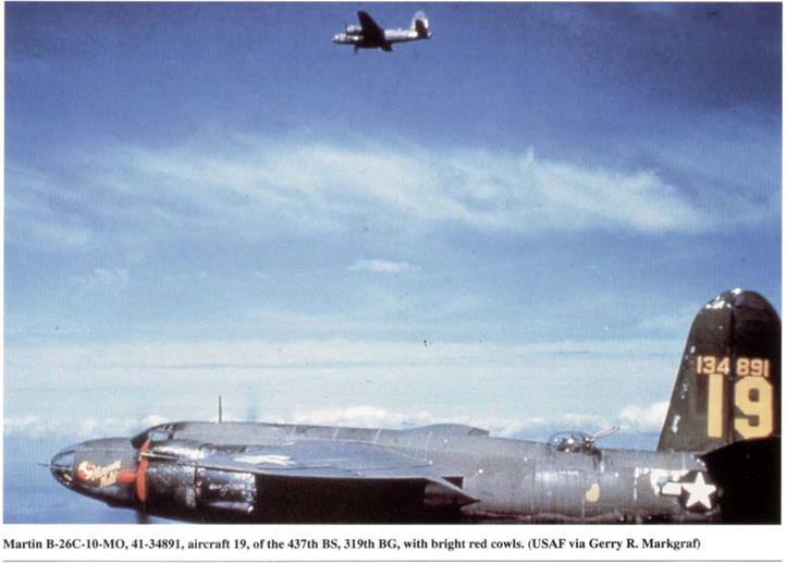
Martin B-26B-25-MA, 41-31844, aircraft SS-S of the 451st BS, 322nd BG, at strip A-8 on August 10,1944, with stripes underneath only. Most of the aircraft that landed at these advanced strips in Normandy did so to refuel. (William L. Swisher)

Unsatisfactory finish on P-61’s discussed by Material Laboratory (WF), March, 1945

A conference was held at Mat. Lab. (WF), between February 23 and 27, 1945, to discuss the unsatisfactory condition of the Jet No. 622 finish on P-61 aircraft being received at overseas bases. It was decided that the problem was probably due to non-conformance to requirements and the use of unapproved enamel. Tests had shown that the enamel finish was definitely improved by use over a zinc chromate primer.

Mat. Lab. recommended that the Procurement Section (WF) should provide Northrop Aircraft with the latest list of approved specs, and that Northrop be requested to use a coat of zinc chromate primer before applying two coats of Jet No. 622 Lacquer to the P-61. They also recommended that the materials being used by Northrop be checked for conformance to spec, requirements.

image392

North American P-51D-20-NA, 44-72747, aircraft 6N-C “Pauline” of the 505th FS, 339th FG, Eighth Air Force. Seen at strip Y-32, Ophoven, Belgium on March 22, 1945. Spinner and nose were in red and white, while the rudder was yellow. (William L. Swisher)

image393

Douglas A-26B-35-DL, 41-39456, aircraft E3-K of the 732nd BS, 453rd BG, Ninth Air Force. The A-26 had a very protracted development and did not start replacing the A-20s until lute 1944, despite the 1941 serial number. (March AFB Museum)

image394

Large number of AAF aircraft seen on Iwo Jima on March 6,1945, includes twenty P-51s, four P-61sof the 548th NFS, two C-47s and one C-46, plus one Navy TBF, Mount Suribachi is prominent in the background. The P-61s are in gloss black, the P-51s arc in natural metal and the transports camouflaged. (USAF)

image395

Curtiss C-46D-I0-CU, 44-77658, aircraft N5-D of the 313rd TCG, Ninth Air Force. It was seen at strip Y-32, Ophnven, Belgium, on March 24, 1945. It had just made an emergency landing after being hit by two 88mm shells while dropping US Army paratroopers over the Rhine at Wesel, Germany, during Operation VARSITY. (William L. Swisher)

CAMOUFLAGE

Camouflaging of the exterior surfaces of AAF aircraft is no longer required except for night fighters and as may be directed otherwise by the Commanding General, Army Air Forces. Aircraft destined for delivery to U. S. Navy and foreign agencies are not included in these requirements. This does not, however, eliminate the identification data, insignia, antiglare coatings, and corrosion prevention.

* * *

3. FABRIC AIRCRAFT

Fabric covered aircraft and all control surfaces will be aluminized when re-covering is necessary or when major fabric repairs are required.

* * *

5. PROPELLERS

d. Helicopter main blades will be aluminized when re-covering or major repair is necessary. A 6-inch yellow tip will be maintained on all tail rotor blades to prevent accidents caused by lack of visibility. The remainder of the tail rotor blades will be maintained in the original finish. Tips of main rotor blades will be maintained in original color. (Refer to paragraph 22. for markings.)

* * *

8. DAY CAMOUFLAGE

Standard day camouflage consisting of upper surfaces olive drab shade No. 613 AN Bulletin 157 and lower surfaces

sea gray shade No. 603 is no longer required. (Refer to paragraph 2,for policy on removal.)

* * *

Request for Sand, Shade No. 26, to be added to T. O. 07-1-1, May 6,1942

On April 24, 1942, Gen Arnold issued a directive ordering the use of Sand, Shade No.26, on the upper surfaces of aircraft operating on sandy or desert terrain. WF ordered initial shipments of ample quantities of the water paint, brushes, buckets, etc..

Dir. of Mil. Req. (Wash.) does not object to anti-submarine tests of white paint, May 8,1942.

The Dir. of Mil. Req. stated on May 8,1942, in a letter to the CG, Material Command that a series of tests over several years had proved that a neutral gray was the best color for camouflage under ordinary conditions. However, there was no objection to the Coastal Patrol aircraft being furnished with oyster white paint for testing. If this shade proved superior, Specs, and Technical Orders should be so revised. Mat. Com. (Wash.) should forward to 1st Air Force any appropriate paint material found.

image105

A training unit Curtiss P-40A. 39-1804, in formation with a natural metal North American AT-6C-NT, 41-32161. The AT-6 has a red stripe on the nose cowl and black number 376 below it on the cowl. Note that the AT-6 has the fuselage insignia star upside down! (Compare it with the P-40 fuselage star.) (USAF)

image106

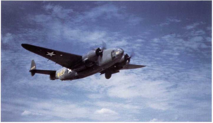
Lockheed B-34A-LO, RAF Ventura Mk. II, AJ165, was one of a batch of 487 built, of which many were transferred back to the AAF under reverse lease-lend agreements. Seen at Wright Field, it was used by the AAF for over-water patrols, primarily in the Caribbean area. (Harry Gann)

Gen. Arnold requests changes to application of camouflage, May 8, 1942.

Brig. Gen, Fairchild also wrote another letter to Material Command on May 8,1942, requesting that revisions be made to Spec. 24114 and T.0.07-1-1, covering the application of camouflage to AAF aircraft. These had been requested by Gen. Arnold as a result of watching paint being applied to aircraft at the Douglas Company. The changes requested were:

(1) Spec. 24114 be revised to change the demarcation line between the upper and lower surface camouflage colors as necessary to prevent appearance of a definite, even and continuous boundary line. Masks will not be employed to separate the two shades, The lines of demarcation shall be eliminated as far as possible by blending the colors at the junction lines by overspraying.

(2) Spec. 24114 should also provide for the use of “haze” paint on special photographic aircraft.

(3) Training Aircraft of wood and fabric covered aircraft to be painted with aluminum-pigmented dope.

(4) T. O. 07-1-1 to be revised to include the use of Sand Shade No. 26 for the upper surfaces of aircraft operating over sandy and desert terrain. Also trainers to be painted as in (3) above. Trainers would only be camouflaged as directed by Theatre of Operation Commanders, Training Center Commanders, or Commanders of posts or schools with the necessary authority.

(5) Variations in the basic aircraft camouflage would permit the use of Medium Green Shade no. 42 instead of Dark Olive Drab when the aircraft operate over terrain so predominately green that the darker shade proves to be unsatisfactory. Sand Shade No. 26 could also replace the Dark O. D. over desert type terrain.

(6) Along the leading edges, tips and trailing edges of the wing, vertical and horizontal stabilizers and rudders, splotches or patches of Medium Green No. 42 were to be allowed to break the continuity in appearance of the wing, stabilizers, and rudder outlines. The size of the splotches or stripes were to extend inward from the edges at various distances ranging from zero to 20% of the wing, stabilizer, or rudder chord. If the aircraft was definitely going to a desert or sandy region, the Dark O. D. might be replaced or painted over with Sand Shade No. 26. The above modifications in the basic camouflage scheme were probably going to have to be made at modification centers or at staging points after the aircraft left the production line.

Use of haze paint for special photographic aircraft camouflage was also suggested. Mat. Com. was asked to initiate necessary action for these revisions. Technical Instruction TI-1111, was issued on May 15,1942 to initiate the requested action. All of the above changes were duly added to revised versions of Spec. 24114 and T. O. 07-1-1.

image107

The same aircraft, B-34A-LO, AJ165, from a rear view shows its RAF camouflage of dark green and dark earth over sky. Note the shine from the decals used for the insignia; these were commonly used throughout the war. (Harry Gann)

image108

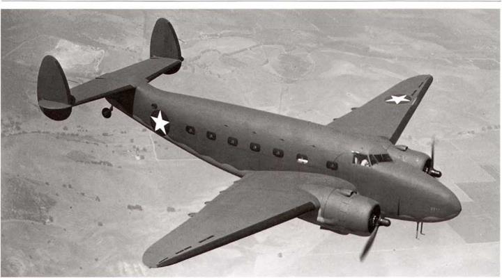
Lockheed Vega B-37-LO, 41-37485, number 16 of a batch of 18 built for the AAF. It was originally intended to build 550 of these as the O-56-LO, but the remainder were canceled. Note that thecocarde only consists of the white star in the fuselage position, without the blue background; this was not to specs., but it is possible that it had not been completed at the time the photo was taken (Harry Gann)

Change in Serial Numbers and Nomenclature, May 11,1942.

Due to the change in nomenclature of the Air Corps to Air Forces, Material Command directed the following change in identifying USAAF equipment:

a. Lettering on trucks and trailers is to be changed from “U. S. Army Air Corps" to “U. S. Army Air Forces”. Also name plates and records with reference to serial numbers of airplanes and engine, are to be changed from A. C. to A. F.

Responsibility for the development of. and requirements for aircraft camouflage defined in Material Command Office Memo­randum No.42-16, May 12, 1942.

(1) The Air Proving Ground Command (Eglin Field), under the Dir. of Mil, Req., was charged with the development of camou­flage colors, designs, markings and insignia for the concealment of aircraft on the ground and in the air, for both day and night operation.

(2) The Corps of Engineers was responsible for developing the use of nets, drapes or other coverings for concealing aircraft on the ground.

(3) Thc Material Center (WF) was responsible for preparing specifications for paint materials recommended by the Air Proving Ground, for approving materials and processes used by aircraft manufacturers in camouflaging aircraft, and for investigating new mate­rials and processes as directed by the Dir. of Mil. Req..

(4) The Air Service Command was responsible for the publication of instructions, and the procurement of necessary materials for the maintenance of camouflage on service aircraft.

image109

North American BT-I4-NA, 40-1305, basic trainer was a development of the BT-9. It is seen here w ithout the rudder stripes and the red center to the cocardes, but is still in the true blue and orange yellow trainer finish. That color scheme was deleted in September 1942 in favor of an all­aluminum finish. (Nick Williams)

image110

Vullee Vengeance Mk. II, AF746, seen unfinished except for the anti-glare panel. This was the second Mk. II built by Northrop out of a batch of 200 aircraft. Most of these were sent to the Burma front as close support aircraft. Note the BT-IJs in the right background. (Convair)

Red center removed from insignia, rudder stripes deleted on combat aircraft, May 12, 1942.

War Department Circular #141, dated May 12, 1942, stated;

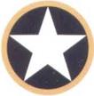
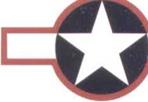
Markings of Military Aircraft. – 1. The red circle in the center of the insignia as used at present will be eliminated. The new insignia will therefore be a five-pointed, white star within a blue circle.

2, The red and white tail marking will be eliminated.

3. These changes will apply to all combat aircraft of the Army and Navy after May 15, 1942.

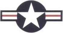
The circular did not state any reason for this drastic action, but it had arisen as a result of extensive combat action in the Pacific area against the Japanese. The Japanese national insignia was the red hinamoru circle and, in the heat of combat, USAAF and Navy pilots tended to fire at any aircraft with red in its insignia. (Note: red was to return briefly in June-August 1943 to the US National insignia, then it disappeared completely until after the end of the war. It returned as the color of the center stripe of the current US insignia in January 1947).

image111

Vultee A-35A-VN, 41-31156 (the eighth A-35A built). This was the AAF equivalent of the RAF Vengeance, and like many of those, these were nearly all converted to target towing aircraft. (USAF)

image112

image113

Vuitee A-3I-NO, RAF Vengeance Mk. II, AF769, in AAF marking!) over the RAF dark green, dark earth, and sky finish. This was a repossessed aircraft, the twenty-fifth of the type built by Northrop. The aircraft number “69” is the last two digits of the RAF serial. fUSAF)


image114image115

Southeast AAF Training Center, Maxwell Field, AL, revises marking and insignia for its trainer aircraft, May 20,1942,

Maj. Gen. Stratemeyer issued General Orders No. 54, revising the marking and insignia requirements for the Training Center’s aircraft to the following:

1. Aircraft in this training center will be marked with identifying numbers as follows:

A. Basic and Advanced – Aircraft belonging to Basic and Advanced Schools will be marked with a code group consisting of an identifying letter or letters for both schools as shown below, plus a digit or digits from 1 to 999, the numbers to be assigned by the station commanders. The letter and number combination will be consecutive with no dash or space between them. The following identifying letters arc assigned:

b.

Подпись: Gunter - G Shaw - S Augusta - A Turner - T Columbus - CO Craig - CR Napier - N Eglin - E Cochran - C Greenville - GR Tyndall - TY Tuskegee - TU Moody - MO Maxwell - M Spence - SP

Primary – Primary aircraft will be identified by a number only. Numbers may run from 1 to 999,

c. Four-Engine Schools – Four-Engine Schools will not use an identifying letter but will use an identifying number of not more than two digits.

2. All identifying letters and numbers will be placed to the rear of the rear cockpit. They will be proportioned and placed in accordance with Para З, T.0.07-1-1, dated April 8, 1941.

3. The radio call letter designator will be placed on the vertical fin of all aircraft in accordance with Para. 8 с. T. O. 07­1-1 A, dated October 23, 1941. On the primary training aircraft the designator will be placed diagonally on the fin, i. e., from the lower left to the upper right comers on the left side of the fin and from upper left to lower right corners on the right side of the fin. Designators will not be placed on the fuselage of any training aircraft.

4. The distinctive insignia of this Training Center will be centered on the fuselage, just forward of the trailing edge of the lower wing.

5. Подпись:
If desired locally, the identifying letters and/or numbers of single-engine aircraft may be placed on the nose cowl for aid in identification. They may also be placed on the nose of twin-engine training aircraft.

image117

Bell P-39D being used as a [raining aircraft. It has the red center overpainted on the cocardes, but retains the “U. S.ARMY” markings under the wing, These were ordered removed from all combat aircraft in May, 1942, but not removed from trainer aircraft until October 1942. (USAF)

The Struggle for Air Superiority in Europe,. North Africa, China, and the Pacific

The USAAF faced an uphill struggle world-wide at the be­ginning of 1943 to gain air superiority. Heavily engaged in Eu­rope, North Africa, and the Pacific, air superiority had not been gained in any of these theaters of operation. Perhaps the closest to this was in North Africa as a result of Operation “Torch”, but the fight against the Luftwaffe was very tough, even with the aid of the Royal Air Force in the Mediterranean area. In Europe, the 8th Air Force had seen much of its strength sent to North Africa and it was just beginning to rebuild. In the Pacific, the various Air Forces were fighting back at the Japanese, but losses continued to be heavy.

However, 1943 was to see a gradual build up to air superior­ity in all of the combat theaters. In Europe, the AAF was to see its cherished doctrine of day bombing brought almost to a halt by intense Luftwaffe opposition, but grim determination and the de­velopment of the long-range escort fighter began to rebuild the impetus, ready for the great air battles of 1944. The Axis forces lost the war in North Africa and the Allies invaded Europe from the south. The Pacific Air Forces grew to a major support of the long battle to dislodge the Japanese from the island chains leading to Japan. The fight of the anti-submarine aircraft in the Atlantic and the Caribbean gradually overcame the deadly anti-shipping menace of the U-boats, breaking their back in 1943.

During 1943, the USAAF continued its massive growth, so much that it more than doubled its strength between June 1942 and June 1943, to more than 49,000 aircraft. However, its losses in action against Germany and over the Pacific also jumped, to more than 3,000 in Europe and the Mediterranean and some 800 versus Japan. These losses reflect both the decision to concentrate on defeating Germany and the large role played in the Pacific by the US Navy.

The intensive development of suitable camouflage, markings and colors for aircraft of the USAAF and its allies continued in 1943, only to culminate in the major decision that camouflage was not necessary at all for most types of combat aircraft! This decision was arrived at tentatively in mid-1943, and put into full effect by the end of the year, causing the biggest change in the USAAF’s aircraft appearance during the war. Ever-growing strength of the AAF led to entirely new types of combat aircraft distinctive mark­ings (see Chapter 6), especially in Europe (the Allies had agreed to defeat Germany before turning their full strength on Japan).

During 1943, the results of world-wide combat experience led to the following major changes in the marking and camouflaging of USAAF aircraft:

Northwest African Air Forces adopt local theater camouflage, March.

Value of camouflage questioned by Gen, Arnold, March.

Dark Olive Drab No. 41 replaced by a new shade, March, effective September.

Markings for walkways and “No Step” markings added, June. Anti-submarine white camouflage finally adopted, June,

T. O. 07-1-1 issued in full-color printing, June.

Star insignia has white bars and a red outline added, June.

Ail trainers to be painted aluminum, or be natural metal finish, June. National insignia outline color changed to insignia blue, Septem­ber.

Names and numbers of Army-Navy aircraft camouflage colors stan­dardized in ANA Bulletin No, 157, September,

Camouflage no longer required for almost all USAAF aircraft, ex­cept night fighters, September.

High Gloss black paint developed for night use, November. Standard aircraft gloss colors for aircraft issued as ANA Bulletin No. 166, December.

Spec. No.

Jan. Feb.

Mar. Apr.

May June

Jul. Aug.

Sep. Oct.

Nov. Dec.

T. O. 07-1-1

Markings,

A

|

New Color Version —

A В

III

C

|

D

|

Major Revision I

Camouflage

Bulletin 41

Colors for

Camouflage

Finishes

Superseded

b^ANA157

September

28.

Bulletin 48

Colors for

Camouflage

Finishes

A-N

Porcelain Color Plates

Superseded

J^NA

іШЗес.4

Spec. 3-1 Color Card

A

x

Superseded by ANA

" 57 & 166

24102

National

Superseded by AN-I-9

Canceled May 21

Insignia

24105

Markings for Airplanes

2 3 | |

К

1

24113

Color for Army Air Forces Airplanes (issue B)

B_

I

Changed

Bronze

Пгррп fn

Dull Dark Green

24114

Camouflage Finishes for Aircraft

ANA 157 Aircraft Camouflage Color Standards

Issued September 28 1

ANA 166

Aircraft Color Standards

(Glossy)

Issued

Decembe^^

AN-I-9

Insignia: National Star

Issued 1 March 1

a

і

b

|

___________

US Army Air Forces specifications in use, revised, or issued, by date and version, during 1943. The letters indicate a letter revision of a spec., such as T. O. 07-1-1 A. The numbers indicate an amendment to an earlier version of a spec., such as Amendment No. 6 to Spec. 24114.

image166

Vultee XP-54,41-210, was the first prototype of this large fighter, designed to the same requirements that resulted in the Curtiss XP-55 and the Northrop XP-56, It made its first flight on January IS, 1943, but the initial trials showed that performance was well below the requirements.

(Convair)


Подпись: ** *

Special black paint investigated for night camouflage, June 1943

On June 29, 1943, the Chief, Req. Div., OC&R (Wash.), requested that the AAF Board, AAF School of Applied Tactics, Orlando, Florida, comment on the use of special black paint for night camouflage. The AAF Board replied that, since the standard olive drab camouflage gave an equally effective protection against searchlights and was better in bright moonlight, special camouflage paint was not only of no particular value, but was extremely undesirable in that it would limit the use of those aircraft only to night operations.

(It seems that this request arose as a result of a report from Eglin Field, No. 3-43-31, “Test of Night Camouflage”, dated June 5,1943, No copy of this report has been found, together with many others issued by Eglin Field during World War II. The author submitted a request for copies of all of these reports in 1967. He was informed that all of the remaining copies were in such a poor state that they could not be copied by any means available at that time, and the author would have to go to Eglin Field to review them. Unable to do so at that time, the author finally got to Eglin Field in 1992, only to find that the current librarian had no record of the location of any of the reports!).

image210

Curtiss AT-9-CS, 41-122K?), has yellow cowls, and is still carrying the “US Army" markings under the wings, but has the 1942-1943 fuselage insignia. (USAF via Gerry R. Markgraf)

White bars and a red border added to the star insignia by AN-I-9a, June 29, 1943.

During combat over North Africa in support of Operation TORCH, it was found that the AAF star insignia was being confused with the Luftwaffe cross at distances exceeding normal resolution (this had also happened during World War I, and led to the adoption of the tri­circle insignia for all AEF aircraft in France).

On June 15, 1943, Eglin Field, was directed to conduct tests on modifying the AAF insignia so that it would not be confused with enemy insignia at distances exceeding normal resolution.

As it so happened, tests had already been conducted earlier and had been reported in Service Test No. 3-42-18, “Revision of Aircraft Marking”, dated May 9,1943. These tests had been run to determine the cause of the confusion at distances (the results agreed with those reported in McCook Field Report No. 1305, dated August 20, 1920, showing that at a distance the white star of the insignia blended into a circular blob).

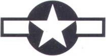
The tests had shown that a long narrow rectangle added to the star insignia proved to be discernible at a distance twenty-five percent farther than the Luftwaffe cross or the AAF star insignia.

Three slightly different versions of the design were finally proposed. The finally selected design of the new insignia was not sym­metrical, but it was considered that this was outweighed by its ease of construction, an important consideration in view of the huge number of aircraft that would have to have their insignia repainted in a hurry.

image211

Supcrmarine Spitfire Mk. Vc, BM181, aircraft MX-D, of the 67th Rec. G, at Membury, England, in July 1943. It carries the new star and bar insignia, outlined in red, adopted on June 29, 1943, to Spec. AN-1-9A. (USAF)

Four P-47s were painted with different insignia; one had the existing star insignia, one the proposed star with the white rectangles, one the Luftwaffe cross, and the final aircraft had the Japanese hinomaru red disc. Flight tests on June 18, 1943, showed that the proposed new design showed up as a rectangle at varying distances and left no confusion of recognition.

A report. No. 3-42-18-2, “Test of Aircraft Insignia”, dated July 7, 1943, was submitted to HQ USAAF, recommending that the new rectangular insignia be adopted as standard. However, in a surprising show of speed, the new insignia had already been adopted by both the Army and Navy, leading to a revised AN-I-9a, dated June 29, 1943. (Contrast this with the lethargy shown on the adoption of a new camouflage scheme for anti-submarine aircraft, as described earlier).

image212

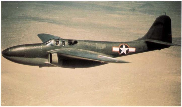
Bell XP-59, no serial visible, prior to May 1943, at Muroc Army Air Base. This was the AAFs first jet tighter, using British designed engines. Its rather poor performance prevented it being used operationally, but it was used for training the AAFs first jet pilots. (USAF)

image213

Boeing B-L7F-85-BO, 42-30033, aircraft BK-Sof the 546th BS, 384th BG, shows the new red outlined insignia, together with the newly adopted “P” in a white triangle showing it belongs to the 1st Combat Bomb Wing, Eighth Air Force. The code letters on the fuselage are in neutral gray. (USAF)

The revised An-I-9a changed the design to the following:

D-l. Construction. – The national insignia shall be an insignia white five pointed star inside an insignia blue circum­scribed circle with an insignia white rectangle, one radius of the blue circle in length and one-half radius of the blue circle in width, on each side of the star and the top edges placed to form a straight line with the top edges of the two star points beneath the top star point; and an insignia red border one-eighth radius of the blue circle in width outlining the entire design. The con­struction of the star is obtained by marking off five equidistant points on the circumscribed circle, and connecting each point to the two non-adjacent points. See Figure 1. The national insignia shall be applied so that in the normal flight attitude of the air­plane one point of the star points upward and perpendicular to the line of flight on vertical surfaces or forward and parallel to the line of flight on horizontal surfaces. A gray color, obtained by mixing one part of insignia white with one part of light gray, shall replace the insignia white on applications to upper wing surfaces when finished semi-gloss sea blue.

D-2a(2). Size. – The insignia shall have a blue circle with a maximum diameter of 60 inches and a minimum diameter of 30 inches. Standard sizes shall have blue circle diameters in multiples of 5 inches. The blue circle diameter selected shall be the standard size which is closest to, but does not exceed 75 percent of the distance between the leading edge of the wing and the aileron cutout at the point of application.

D-2b. Fuselage Insignia.

D-2b(l). Location. – On patrol seaplanes, the insignia shall be applied to each side of the bow, in such position that it is completely visible when the plane is water borne in normal load conditions.

INSIGNIA RED

-INSIGNIA SLUE

INSIGNIA WHITE


INSIGNIA WHITE


INSIGNIA WHITE


INNER END OF
EACH RECTANGLE
CONFORMS TO THE
CONTOUR OFTHE CIRCLE


Tech. Order No. 07-1-1В
(June 29 1943 )

© Victor Archer


image214image215

Special black paint investigated for night camouflage, June 1943

image216

Douglas C-53, painted to T. O, 07-1-1. insignia to T. O. 07-1-1B, June 29 1943. Fuselage insignia 50 inch diameter circles, wing insignia 55 inch diameter circles. Dased on Douglas drawing 5133360.


Fire extinguisher marking, placed to right of door, to the left of insignia.

By rear door only.


image217

image218

Curtiss P-40E-CU, 41-3650, was originally built Гог the RAF, but was taken over by the AAF while on Ihe production line. Thus, it is in standard AAFcamouflage, including rather heavy medium green blotches on the wings and tail surfaces. There is a yellow “1” on the cowl side, and the aircraft is using the new, but short-lived, red-outlined star and bar insignia of June 29, 1943.

AIRCRAFT CAMOUFLAGE

a. Painting of the exterior metal surface of Army Air Forces aircraft is hereby discontinued, except as may be directed otherwise by the Commanding General Army Air Forces for aircraft destined for delivery to foreign agencies. This does not, however, eliminate the required identification data, insignia, anti-glare coatings, and corrosion prevention. Man-hours expended on maintaining existing camouflage finishes, now considered unnecessary, will be held to a minimum.

b. Paint may be removed from presently painted metal aircraft by the operating organizations at the discretion of Commanders concerned, as local facilities and materials are available, provided no interruption in operations is entailed. Alumi­nized parts installed on a camouflaged aircraft will not be camouflaged. However, when any unpainted metal surface of suffi­cient area is installed that would materially affect the flight characteristics of the airplane, the remaining camouflage paint may be removed. Camouflaged metal parts installed on unpainted airplanes need not have camouflage removed.

image257

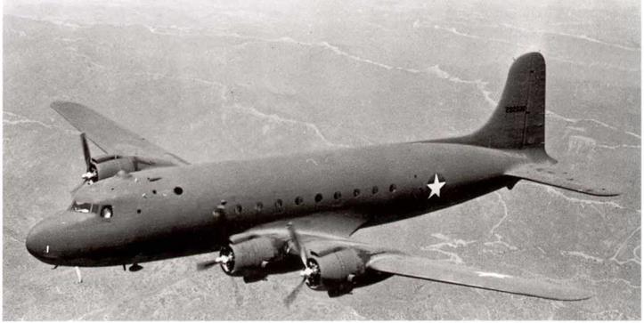
Nice view of the Lockheed C-69 shows its very clean lines, which made it a classic airliner after the war. Note the natural metal finish and the extensive wing and horizontal tail walkway markings. These markings had been adopted in June 1943. (BUAER)

c. All fabric control surfaces and fabric-covered aircraft will be aluminized when re-covering is necessary.

d. PARTS IN STOCK.

(1) Aircraft airfoils and other exterior metal parts in stock need not have the camouflage paint removed.

(2) Fabric control surfaces in stock, or installed as replacements, need not be refinished for any color match­ing purposes.

e. Camouflage black need not be applied to propellers unless required for antiglare purposes or corrosion resistance; however, the 4-inch yellow tip must be maintained as a safety measure. Repaired hollow steel blades from which any of the protective plating has been removed will be painted as outlined below, to protect against corrosion. Wood propellers will not be painted black.

(1) If camouflage black is to be used for antiglare or corrosion resistance purposes, it will be accomplished by spraying the hub and each propeller blade while in a horizontal position, and retaining the propeller in this position until the camouflaging materials have set. Over one light coat of zinc chromate primer, Specification No. AN-TT-P-656, one light coat black cellulose nitrate camouflage lacquer, shade No. 44, will be applied and will extend to within 4 inches of the tip of the blade; this 4-inch tip section will receive one light coat of yellow lacquer, shade No. 48, The propeller will then be checked for balance.

(2) When necessary, three-and four-blade metal propellers may be lightly touched up between overhaul periods, while installed on the airplanes. Care will be exercised to apply proportionate amounts of paint to each blade to maintain proper blade balance.

SPECIALTRAINER MARKINGS

(1) Painting of ring cowls is authorized in colors as directed by the Commanding General of the AAF Training Command,

(2) Field identification numbers and radio call letters are authorized, as designated by the Commanding General of the AAF Training Command for use in Army Air Forces Training Organizations and Civil Flying Schools. They will be of contrasting color, preferably block type, and will be applied to opposite sides of the fuselage in front of the insignia. The height will be the greatest practicable for the location required.

(3) Aircraft used only for instrument training may be distinguished, at the discretion of the Commanding General of each particular Command, as follows, except that such markings will not be applied to first line combat type aircraft.

image319

Cessna UC-78-CE, 43-7778, group “hack" of the 405th FG, Ninth Air Force, seen at strip A-8 in early August 1944. It is in standard camouflage, with invasion stripes on the lower surfaces. Note the P-47 of the same unit in the background. (William L. Swisher)

image320

Northrop P-61 A-l-NO, 42-5507, in Dark Olive Drab and Neutral Gray finish with light gray radome. Note the red radio call number on the rear of the boom. Seen on test over Southern California. (USAF via Gerry R. Markgraf)

(a) Rudders and vertical fins painted Insignia red.

(b) Insignia red stripes, 18 inches wide, extending from junction of leading edge of wing and fuselage, diagonally (45 degrees to axis of the plane) to the trailing edge of the wing, top and bottom.

(c) Ring cowls to be painted insignia red.

(d) Multienginc aircraft nose sections to be painted insignia red from the cockpit forward,

e. Markings and insignia may be made with any of the following materials:

(1) Enamel, Specification No. 14109 or No. AN-E-3(3-98).

(2) Insignia colors in oil. Specification No. 3-120.

(3) Lacquer, Specification No. 14105 or No. AN-TT-L-51 .

(4) Dope, Specification No. 14106 or No. AN-TT-D-554.

image321

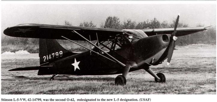
Stinson L-5-VW, 42-99005, aircraft 9S-J, of the 14th Liaison Squadron, Ninth Air Force, at strip A-8 on August 13, 1944. This aircraft has bad the upper portion of the invasion stripes painted over on the Tuselage and upper wing surfaces. It also still carries (he 1943 medium green blotches on the wing and tail surfaces. (William L. Swisher)

INSIGNIA BLUE

INSIGNIA BLUE

INSIGNIA WHITE


П 1

[ж.


INSIGNIA WHITE


1/2 R


INNER END OF
EACH RECTANGLE
CONFORMS TO THE
CONTOUR OF THE CIRCLE


INSIGNIA WHITE


Tech. Order No. 07-1-1
( April 25 1944)

© Victor Archer


image322image323image324

SPECIALTRAINER MARKINGS

image325

Martin B-26G-1-MA, 43-34118, aircraft U2-N of the 596th BS, 397th BG, Ninth Air Force, seen at strip A-8 on August 10,1944. This one is still in its original all-natural metal finish. Unit stripe on the fin is yellow with black trim. (William L. Swisher)

The Spoils of War

image396

A few days after the end of the war in Europe on May 8, 1944, Capt. William L. Swisher made a quick tour of many ex-Luftwaffe bases. His photographs are an excellent record of the “spoils of war”. This is an Arado Аг 96B, 4658, aircraft CD+XF. It had the no. H4 under the cockpit and E-III on the rudder, significance not known. It has the white US star painted over the Luftwaffe cross and was being used as a squadron “hack". Location unknown, seen on May 15, 1945. (William L. Swisher)

image397

Siebel Fh HI4A with the US blue outlined insignia. Location not recorded, seen in May 1945. It was also being used as a squadron “hack”. (William L. Swisher)

%

image398

Goth» Go 150, FG-1163, registered D-E??D, seen at field R-30, Kuril), Germany, on May 8,1945. It has had the LIS star and bar insignia painted over the last three letters of the registration. The swastika on the tail band has been over-painted. (William L. Swisher)

image399

Messerschmitt Me 109G-6, unit no.9 seen at field R-80, Salzburg, Austria, in May 1945. (William L. Swisher)

image400

Focke-Wulf Fw 190A-8, 580351, coded 1+5, seen at field R-68, Strauhing, Germany, on May 11,1945. Il is in immaculate condition. (William L. Swisher)

image401

Focke-Wulf Fw 190D-9, 500570, aircraft 12+bar, believed to be of I1T/JG54, seen at field R-30, Furth, Germany, on May 8, 1945. Behind is a Lockheed K-5C, of the 31st PRS, 10th TRG. (William L. Swisher)

image402

Me. ssersehmitt Bf 110G-4d/R3, aircraft G9+DC of NJG-1 in May 1945, Location unknown. Note the Heinkel He 111 behind. (William L. Swisher)

image403

Messersehmitt Me 410A-3, 10047, aircraft 5T+DN of unit KSG-1. Location unknown. Seen in May, 1945. Note the side gun barbette on the fuselage. A superficial resemblance to the RAF DeHavilland Mosquito led to many of the latter being attacked, mis-identified as Me 410s. (William L. Swisher)

image404

Junkers Ju 88S-1, aircraft RG+RW, seen at field R-71, Lechfeld, Germany, on May 25, 1945. (William L. Swisher)

image405

Dornier Do 217E-1,1104, aircraft FF+CD, seen at field R-19, Nordhausen, Germany, on May 28,1945. Note the forward “Mistal” attachment struts on the fuselage aft of the cockpit. (William L. Swisher)

image406

Messerschmitt Me 262A-1A, 111755, seen in an Autobahn revetment, ten miles west of Augsburg, Germany, on May 25,1945. Unlike many of these at this time, this Me-262 appears to be in perfect condition. Note the large stand of very upright trees, giving very good concealment from air attacks. (William L. Swisher)

image407

Heinkel He 162H-20,220003, aircraft “M20”, without its engine and in a somewhat bent condition. Seen at field R-82, Munich/Reim, Germany, on May 25,1945. (William L. Swisher)

image408

Biicker Bii 131 trainer, seen at R-82, Munich/Reim, Germany, on May 25,1945. It has its former operators’ markings painted out and replaced by the new owners’ star-arid-bar insignia This was a superb training aircraft and much prized. (William L. Swisher)

17. RADIO CALL AND IDENTIFICATION MARKINGS

a. Radio call numbers of not less than four numerals will be maintained on all AAF aircraft except as stated in paragraph 17.c. These will be applied to both sides or each outboard side, as applicable, of the vertical stabilizer and rudder assembly, except that on rotary winged aircraft, they will be applied to the sides of the fuselage. These call numbers, or designators, will be of a size discernible at a distance of 150 yards. The suggested minimum size is 8 x 12 inches. They will be derived by deletion of the first numeral of the serial number (4) and the hyphen (-), and the combination of the remaining four or more numerals. In case of serial numbers of type 41-7, use zero as necessary to make four numerals as 1007. Colors will be black for uncamouflaged surfaces, and yellow for camouflaged surfaces except that black camouflaged planes will have insignia red call numbers. Decalcomanias are authorized if available,

b. IDENTIFICATION MARKINGS.

(1) On all aircraft, except helicopters and lighter than-air, operating solely within the continental limits of the United States, an identification marking will be placed on the lower surface of the left wing, and each side of the fuselage if space permits without relocation of the insignia. These identification markings will consist of two letters and three numerals determined as outlined below. Letters and numerals will be of uniform size, with the letters separated from the numerals by a dash.

NOTE If any duplication of identification symbols should occur on permanently assigned aircraft at any one installa­tion, a suffix letter may be used to further identify the aircraft. The suffix letter will be of a size and so placed so that the size of the basic identification symbol is not reduced.

(2) The wing markings will be centrally placed on single engine aircraft and will be placed outboard of engine nacelles on other aircraft, with the top of the letters and numerals forward. The letters and numerals will be the same height as the star in the wing insignia, with the width two-thirds the height, width of strokes one-sixth the height and with spacing one – sixth the height.

(3) The location of the fuselage markings will depend upon the fuselage surface available therefor. They will be the largest size practicable, determined by available space, however, in no case will they be smaller than 8×12 inches, or larger than 32 x 48 inches. The proportion of width, and length of the stroke, to the height will be the same as that of wing markings insofar as practicable.

(4) Identification markings will be yellow on camouflaged surfaces and black on aluminized surfaces, and of either gloss or lustcrless enamel or lacquer.

(5) The first letter of the identification marking will identify the type of aircraft, the second letter will be an equivalent for the model number and the numerals will be the last three numerals of the serial-number. The tetters to be used for the various types and models, together with an example of the identification markings of a specific aircraft of each type are set forth below:

(The following new aircraft were added to the Glider section of this paragraph):

image448
(The following paragraphs were added or revised):

17.c. Radio call numbers are not required on primary trainers which do not have radio equipment and which bear field identifying numbers; however, identification markings required by paragraph 17.b. are applicable to primary trainers.

19.g. Helicopters used in pilot training may have fuselage finished international orange color shade No. 598 for pur­poses of visibility.

* * *