Category And Colors

Camouflage Paint on USAAF Airplanes in the United Kingdom, January 2,1944

Gen. Eaker sent a letter to the CGs,, Ninth Air Force, VIII Bomber Command and VIII Fighter Command, on January 2,1944. This stated that in the near future, certain types of aircraft arriving in the theater would be uncamouflaged. The Generals were directed to notify the VIII Air Force Service Command as to their intentions regarding the use of uncamouflaged combat aircraft, at the earliest possible date. The final decision in this regard was to remain in the hands of the responsible Tactical Commander.

The policy in the theater concerning use of uncamouflaged aircraft would be established through the decisions reached as above. This letter gave the Tactical Commanders concerned the authority to operate their combat aircraft without camouflage if so desired.

On January 15, 1944, Ninth Air Force HQ. replied to F. aker’s letter, stating that their policy would be as follows:

a. Fighter Aircraft. All operational fighters used by IX Fighter Command would be camouflaged, and any uncamouflaged aircraft received would be camouflaged. This would cause extra work for the depot and service units and they would prefer to receive all fighters destined for IX AF in camouflage. They also would, if possible, polish the camouflage paint to attain the equivalent of an RAF “fighter finish”, as this would give them the same performance as uncamouflaged aircraft.

b. Bomber Aircraft. The IX Bomber Comand would use either camouflaged or uncamouflaged aircraft, in an “as received” state. Aircraft delivered uncamouflaged would not be painted, nor would paint be removed from those already camouflaged. No change in operational tactics was anticipated for uncamouflaged aircraft.

c. Troop Carrier Aircraft. The IX Troop Carrier Command did not want to use uncamouflaged aircraft, and any uncamouflaged aircraft delivered to them would be camouflaged before delivery to combat units.

image273

Boeing B-17G-5-BO, 42-31134, aircraft CC-G of the 569th BS, 390th BG, taking part in the major offensive against the German aircraft industry in February 1944. Note the while rectangle with the black letter “J” within it; it has usually been called a “square”, but the orders clearly defined a rectangle. It could be seen in a horizontal position on aircraft with wide code letters (see chapter 6 for more information). (USAF)

Four Boeing B-17Gs of the 323rd BS, 91st BG, 1st CBW, 1st Air Div, Eighth Air Force, over clouds with bomb doors open. Lead aircraft is in Dark Olive Drab and Neutral Gray, with yellow code letters OK-K, others all in natural metal, code letters OK-C, S, and K. Note how the red tail markings show up the different color triangles on the Olive Drab and natural metal aircraft. (ESAF)

image274image275"Material Command issues Military Requirements Policy No. 60, concerning AAF insignia on leased commercial aircraft, Janu­ary 6, 1944.

To clarify any misunderstanding concerning the camouflage of AAF aircraft, Material Command issued Military Requirements Policy No. 60 on January 6, 1944. This stated that Army camouflage, insignia and markings were not to be used on any commercial aircraft leased to the AAF, but not flown by AAF crews. Such camouflage, etc., was to be used on any commercial aircraft leased to the AAF for a continuous period exceeding ninety days, which was flown and maintained by AAF personnel. Any AAF aircraft loaned to any other government agency and not flown by AAF crews were to have all Army camouflage, insignia and markings removed before delivery.

Preparation for Stripping

If possible, stripping should be done in the open air but not in direct sunlight. To be satisfactory, inside locations must be well ventilated. Personnel should be kept out of the airplane during stripping and the subsequent clean-up procedure. Aircraft should not be stripped on asphalt floors or runways as the paint remover will attack asphaltic base materials.

In order to allow workmen to apply the remover over large areas, arrange ladders and platforms to permit easy access to the surfaces which are to be stripped. Rubber-surfaced equipment should not be used because contact with the paint remover will make it very slippery.

Mask off or remove all exposed parts consisting wholly or partly of plastic, rubber, fabric or other поп-metallic materials, and all painted areas not to be stripped. For masking, use waterproof cloth or a double thickness of Kraft 40-pound paper and masking tape. Because the parts to be removed or masked off differ from one model to another, the following list will serve only as a general guide.

1. De-icer boots and attaching fairing strips. Overlap the camouflage finish approximately 11/2 inches from the trailing edge of the fairing strip.

2. Windows, windshields, navigator’s dome, and the weather sealing used around these parts.

3. Fabric-covered control surfaces: These surfaces should be removed unless they can be masked off completely and adequately. If removed, place them a safe distance from the airplane to avoid possible splashing or excessive exposure to fumes from the remover.

4. Landing gear and tires: In addition to masking off the landing gear and tires, the airplane must be jacked tip and placed on blocks at least one inch thick to avoid possible contact with the remover.

5. Air scoop, oil cooler, and other openings and vents: Mask off all openings through which the remover can gain access to the interior surfaces of the airplane.

6. Demountable power plant assemblies: The antidrag rings and cowl flaps should be removed and the complete power plant assembly covered with waterproof cloth.

7. Propellers, hubs, and domes.

8. All open seams, such as those around the pilot’s door, escape hatches, cargo compartment doors, and fuel tank access doors.

image356

Consolidated B-24J-35-CO, 42-73318 and B-24J-25-CO, 42-73253, of the 425“’ BS, 308,h BG, on their way to bomb targets in Sinshih, China. Standard camouflage, with yellow stripes on the O. D. rudders. They are being escorted by Curtiss P-40s of the Nth Air Force, China. (USAF)

9. All weather-sealed joints between the nose section and the fuselage, between various sections of the fuselage, and between the fuselage and the tail cone.

10. Ail miscellaneous rubber, neoprene, Plexiglas, and other non metallic parts, and all painted areas not to be stripped which may be contacted by the paint remover.

WAR-WEARY AND SURPLUS AIRCRAFT

Two-inch letters will be stenciled directly beneath the type, model, and series designation on the fuselage of aircraft (with insignia red paint materials) in the following categories. This stenciling will be applied by activities at which the affected aircraft are now stationed, and will also include affected aircraft received in the future without these markings:

a. The letter “W” will be stenciled on ail war-weary aircraft which have not undergone a complete DIR. The term “WAR-WEARY” applies to any aircraft returned permanently from service in an overseas theater.

image425

Another view of the 343rd FG P-38L-5-LO, al Shemya in September, 1945. (USAF via Gerry R. Markgraf)

b, The letter “Q” will be stenciled on all war-weary aircraft that are processed through a depot for DIR. This symbol will replace the “W,” which will no longer appear on the aircraft.

c. The tetter “S” will be stenciled on all aircraft which have been declared by Headquarters, Army Air Forces, excess to the military requirement or surplus to the War Department or both. (Reference paragraph 9.a., AAF Regulation 65-86.) Under no circumstances will the letters “S" be used to indicate, or be interpreted to mean, “storage.” In cases where the symbol “W” or “0” is required to be placed on the aircraft, the “S” will be stenciled directly after that symbol. Example: “WS” – “QS.”

Propeller Blades and Hubs to be black, May 1941

Steady progress in the development of new camouflage finishes and requirements inevitably led to continued amendments to Spec. 24114. Unfortunately, Amendment No. 2 has been lost (therefore there is no exact record as to what was said in it). Amendment No. 3 dated May 9, 194І, specified that all propeller blades and hubs should be painted matt black on all surfaces. Paragraph E-5 required that:

All external surfaces of airplane propellers and hubs, after the provisions of Paragraph E-la have been complied with, will be sprayed with one coat of zinc chromate primer, Specification No. 14080. The final finish shall consist of one light coat of cellulose nitrate camouflage lacquer, Specification No. 14105. The color of all external surfaces shall be black in accordance with 14080. The final finish shall consist of one light coat cellulose nitrate camouflage lacquer. Specification No. 14105. The color of all external surfaces shall be black in accordance with Shade No. 44, Bulletin No. 41. After the propeller and hub have been camouflaged and prior to installation, the propeller assembly will be checked for balance.

This was to be the last amendment to Spec. 24114 issued by the Air Corps, later ones being issued by the Army Air Forces.

image43

image44

Boeing B-17B of the 19th BG, March Field, shows the standard “U. S. ARMY” marking under the wing. The two underwing cocardes were replaced by a single one under the right wing in Spec. 24114. (March AFB Museum)

image45

image46

Boeing B-17E-BOs, 41-9141 and 41-9131, flying near Seattle are in two different finishes. The nearest one has been repossessed from an RAF batch and is painted in dark green and dark earth over deep sky, with an RAF fin flash, while the other one is in dark olive drab and neutral gray. 512 of this version were built and were considered to he the first real combat-ready B-17. (USAF)

Colors for TVaining Airplanes (Specification 98-24113)

Colors for Advanced, Primary, and Basic trainers were called out in Spec. No. 98-24113-А, dated September 9,1938, and the appli­cable portions follow (with the colors corrected to the new Army-Navy Porcelain Color Plates of September 1,1938):

image47

Spec. 98-2411Э-А, Color for Army Air Corps airplanes

Exterior (Exposed) Surfaces.

Primary and Basic Training Airplanes

Advanced Trainers

Ailerons-both surfaces

Orange Yellow

Aluminum (1)

Cowling

True Blue

Aluminum (1)

Elevator-botb surfaces

Orange Yellow

Aluminum (1)

Fins-bolh surfaces

Orange Yellow

Aluminum (1)

Flaps-both surfaces

Orange Yellow

Aluminum (1)

Fuselage

True Blue

Aluminum (1)

Fairing, fuselage-wing

True Blue

Aluminum (1)

Horns, fittings, etc.

Color of surface to which attached

Aluminum (1)

Rudder, balanced section

Orange Yellow

Aluminum (1)

Rudder, aft of rudder post

Standard rudder insignia

Standard rudder insignia

Skis

No added finish

No added finish

Spinners

True Blue

Aluminum fl)

Stabilizers-both surfaces

Orange Yellow

Aluminum (1)

Struts-landing gear

True Blue

Aluminum Ш

Struts-wing

True Blue

Aluminum (1)

Struts-wire braces

True Blue

Aluminum (1)

Struls-fairing

True Blue

Aluminum (1)

Step-plates

Black

Aluminum (1)

Tail Wheel Fork

True Blue

Aluminum (1)

Walkways

Black

Black

Wings-both surfaces

Orange Yellow

Aluminum (1)

Wheel Cowling

Aluminum

Aluminum (1)

Highly Reflecting Surfaces i. e. The fuselage decks forward of the pilot’s compartment and the inboard side of engine nacelles.

Flat Bronze Green (3)

Flat Bronze Green (3)

Interior (Enclosed) Surfaces

Primary and Basic Training Airplanes

Advanced trainers

Wings and Control Surfaces, including ribs, spars, and all interior structures

Optional

Optional

Fuselages, excepting compartments for personnel, luggage, and cargo

Optional

Optional

Cockpits for pilots and observers which are open or for which sliding enclosures are provided

Yellow Green (2)

Yellow Green (2)

Closed cockpits, the top and sides of which form part of the fuselage structure

Floor and sides to tops of windows: Flat Bronze Green No. 9 (3). Sides above windows and ceilings: aluminum

Floor and sides to tops of windows: Flat Bronze Green No. 9 (3). Sides above windows and ceilings: aluminum

Seats and upholstering for seats, carpets, drapes, etc.

Flat Bronze Green No. 9 (3).

Flat Bronze Green No. 9 (3),

Luggage, cargo and bomber’s compartment

Yellow Green (2)

Yellow Green (2)

NOTES:

(1) Parts and surfaces fabricated from the following aluminum alloys and corrosion resistant steels are used in the natural metal finish without paint coatings, except anti-glare coating:

Aluminum covered Aluminum Alloy, Specification No. 11067.

Aluminum Alloy, Specification No. 11072.

Aluminum Alloy, Specification No. QQ-A-359.

Aluminum, Specification No. 57-151-1.

Corrosion Resistant Steel, Specification No, 11068.

Parts and surfaces manufactured from other metals or fabric shall be finished with aluminum, enamel, lacquer or dope as specified.

(2) Yellow Green is prepared by mixing:

Zinc Chromate Primer, Specification No, 14080 -1 gallon.

Black Enamel, Specification No. 3-98 – 1/10 gallon.

Aluminum Powder, Type B, Specification No. TT-A-476 – 4 ounces,

Toluene, Specification No. 50-11-38 -1 gallon.

(3) Flat Bronze Green is to match color chip No. 9, Color Card Supplement Specification No. 3-1. The lacquer or enamel shall produce a matt appearance of minimum gloss.

image48

Douglas XB-19, 38-471, in flight over Santa Monica with an AT-6. It first flew on June 27, 1941, in natural metal finish, and was the largesi aircraft to enter AAF service until the B-36. (Nick Williams)

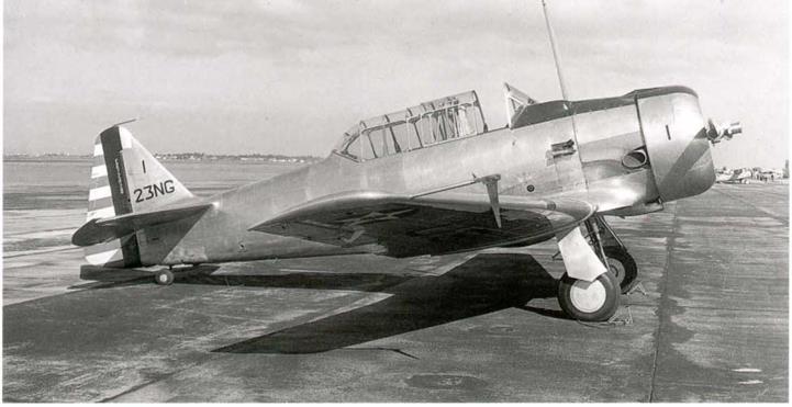
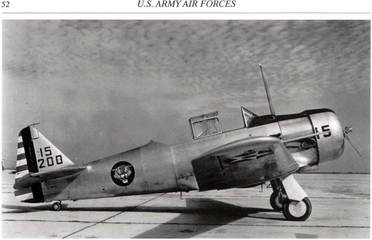
These requirements covered primary and basic training airplanes finished in the true blue and orange yellow color scheme, together with advanced trainers finished in aluminum or natural metal finishes. This spec, also covered the interior yellow-green color; this was not matched to any specific color chip, but was prepared by mixing zinc chromate primer, black enamel and aluminum powder, as specified.

Thus, just prior to entry into World War II, the Army Air Forces had no less than three standard trainer aircraft finishes; (1) the orange yellow and true blue scheme; (2) aluminum paint finish; and (3) natural metal finish.

Placing Star insignia on side of training aircraft objected to in view of very large number of aircraft that would have to be repainted, August, 1942

The War Department Circular No. 273, August 18, 1942, required that all trainer aircraft would have to have the star insignia painted on the fuselage, aft of the wing. The Southeast Air Forces Training Center, Maxwell Field, AL, pointed out that to meet this rquirement, not only would they have to expend a lot of effort on painting the insignia on all of their approximately 4,600 aircraft, but that they would also have to remove the field letters and numbers on all of these aircraft. They felt that the letter and field numbers were necessary for ready identification of aircraft in their training program. Thus, they requested if it was possible to have trainer aircraft excluded from the requirements of the circular.

The HQ. Air Forces Flying Training Command, Fort Worth, TX, to whom the above objection had been sent, in turn wrote to the Director of Individual Training, AAF, Washington, stating that there were approximately 15,500 training type airplanes in the Flying Training Command that would require a change of insignia in order to comply with W. D. circular No. 273. They requested that to avoid interruption of training schedules, and to conserve labor and materials, that the Circular be amended to exclude training type aircraft assigned to the AAF Flying Training Command.

Meanwhile, Maxwell Field, on September 29,1942, sent a letter to the Director, with recommendations for applying the star insignia to the fuselages of in-service training aircraft.

In reply, on October 12, 1942, the Director stated that the Aeronautical Board had proposed the following suggestions regarding the fuselage insignia; these were, if approved, going to be issued as anA-N spec. A maximum diameter of 50 inches and a minimum diameter of 20 inches were to be used for the fuselage insignia, standard sizes to be in multiples of 5 inches. The diameter to be used was the standard size which came closest to being 75 percent of the fuselage depth at the selected location. It was believed that the specified size and location of the fuselage insignia would leave adequate space on training airplanes for their identification markings.

It was also stated that, pending more definite information and the issue of appropriate instructions and technical orders, no action was to be taken by Flying Training Command to alter the markings on their aircraft.

image158

Boeing B-17F-27-BO, 41-24639, was the last of the -27 block and is seen flying near its Bassingbourne, England, base in late 1942. It carries the yellow code letters of the 323rd BS, 91st BG, assigned to the 1st Bomb Wing, Eighth Air Force. (USAF)

image159

Curtiss P-40C-CU, 41-13468, of the 31st FS in the 6th AF, Caribbean area. It is shown in its net-covered revetment; note the shadows on the aircraft’s camouflage. Photo taken in December 1942. (USAF)

image160

Yellow outer ring added to lower wing and fuselage insignia for aircraft destined for use in invasion of North Africa, in Amendment to Op. Memo No. 9 for operation “Torch," dated September 30,1942,

In preparation for Operation “Torch”, the Allied invasion of French North Africa, an amendment dated September 30, 1942, to Operation Memorandum No. 9, dated September 25, 1942, was issued by Allied Force Headquarters under Gen. Eisenhower’s command. This amendment added a yellow ring around the star insignia on the fuselage and under the wing of all American aircraft taking part in this invasion. Intended for ground recognition, it was not required for use on the upper wing insignia. (However, it is obvious from photographs that many aircraft also carried the ring on the upper wing insignia – author). An order adding a two-inch thick ring to the fuselage star insignia was also issued by Gen. Spaatz on October 1,1942, in England for USAAF aircraft in the European Theater of Operations. It has been suggested that this yellow ring was added to the insignia to make it more resemble the British roundel and thus help reduce resistance to the invasion by the local French troops: they were considered to be more friendly to the U. S. forces than to the British forces, who had recently shelled the French Fleet in its home port to prevent it falling into Axis hands. (The later adoption of RAF type red, white, and blue fin flashes on USAAF aircraft serving in North Africa also lends credence to this suggestion – author.)

Replies to Arnold’s teletype re development of camouflage tabulated, April 17,1943

The replies from the different theater commanders were collected and are paraphrased below as far as bombardment types were con­cerned:

London. – Subject appreciable increase in speed, removal of camouflage from heavy bombardment types favored. Removal same from underside only of medium types favored. Bases reasonably safe from surprise attacks due to modem radar so value of passive defense of camouflage in air is deleted.

Alaska. – With 20 miles per hour increase in speed, believe non camouflage of airplanes more desirable in this theater if nets are available for camouflage of aircraft on ground. Believe speed increase due to weight reduction rather than glossy surface.

Brisbane. – At this time do not desire removal of camouflage from airplanes for this theater.

Cairo. – Further camouflage not required as long as airplanes given dull neutral color not reflecting sunlight.

4th and 11th Air Forces, – Desirable removal of camouflage all types except transports.

Hawaii. – Recommend no paint on top, sky blending camouflage on bottom, propellers to be painted antiglare. In ac cordance with background, top to be camouflaged locally.

As a tentative conclusion, it was suggested that:

Due to the early warning and vectoring capabilities of radar, camouflage is losing its importance when weighed against the cost in speed and weight.

A compromise along the following lines was suggested for bombardment types:

(1) Reduce the weight of the camouflaging materials to as low a weight as possible consistent with changing the metallic sheen of the ship to a less conspicuous appearance.

(2) Allow the surface to be roughened to a minimum extent to somewhat reduce reflection consistent with the smoothness of surface required for low drag. Some reflection could be tolerated if a minimum of roughness was obtained,

(3) Following documents noted as having important bearing on subject:

(a) Final report on Experimental Camouflage Finish for Aircraft, dated March 8,1943 (Eglin Field).

(b) Memorandum Report on Camouflage of Aircraft in Flight, dated October 27,1942 (Eglin Field).

(c) Report on Conference on Special Camouflage for Anti-Submarine Aircraft at Langley Field, Virginia, dated September 16,1942, (Eglin Field).

These comments and recommendations were withheld from further distribution until all answers had been received from the theater commanders. However, a memo to the Bombardment Branch of the Requirements Division, the Air Support Branch (of the same divi­sion) stated:

Six replies had been received with five widely varying answers. If these answers were typical of the other replies to be received, camouflage would have to be provided for each type of theaters requirements. To date, a sky blue to dull drab camou­flage had been desired by two of the theaters. Camouflage had to fit the terrain condition, the tactical tasks being performed and the passive type of protection required for the theater.

Further remarks could not be made until all replies had been digested. However, it appeared that it would be necessary to provide camouflage for each theater as necessary to fit the particular situation.

Photographic B-24s (F-7s) to be painted two shades of blue, October 16, 1943

The Mat. Lab. at WF in a letter, dated October 16,1943, advised the AAF Representative at Northwest-St. Paul Modification Center that B-24s being modified to F-7s for photographic purposes, should be thoroughly cleaned, sprayed with a hiding coat of aerial blue enamel, followed by sufficient coats of shadow blue enamel to produce shading over visible bottom surfaces. (Note: this is a most remarkable letter, because it contains reference to two enamel colors, aerial blue and shadow blue, which have never appeared anywhere in any paint orders, standard color listings, etc.! Research has not been able to find any other official reference to these colors, nor did they ever find their way into any of the AN standard aircraft camouflage colors).

Paint manufacturers query the variety of color standards in use, October 1943

The Forbes Varnish Company, Cleveland, OH, on October 22, 1943, asked the Material Division, Wright Field, OH, whether or not certain of the gloss colors in the Army-Navy Porcelain Color Standard had been superseded by certain color chips in “Color Card Supplement to US Army Spec. 3-1, revised April 21,1943.”

The Production Engineering Section replied that the Color Card Supplement colors did not supersede any of the Army-Navy Porcelain Standard colors, and pointed out that in each instance the correct color standards to use would be those referenced in the applicable detail specifications (see Chapter 7 for full details).

Gen. Arnold signs order eliminating camouflage on all aircraft, October 30, 1943

On October 30, 1943, the Prod. Eng. Sect. (WF), informed by teletype the Western Procurement District, Los Angeles, CA, that Lt. Gen. 13. Giles, С/As (Wash.), had signed an order, which had been counter-signed by Gen. Arnold and Lt. Gen. Carl Spaatz (Northwest African Air Force), eliminating camouflage from all aircraft. WF had not then officially received the order, but suggested that the District withhold for one week, approval of any funds for paint buildings.

Proving Ground Command issues Final report on the principles for camouflage in flight, January 7, 1944

Подпись: Vultee XA-41-VG, 43-35124, was the prototype for a new attack aircraft which made its first flight on February 11, 1944. Shown in natural metal finish. It was canceled because the fighter bombers such as the P-47 made it redundant. (Convair)

Eglin Field prepared a long and detailed report on the principles applicable to the camouflage of aircraft in flight. This stated that there were four fundamental variables in the perception of any visual object, – (1) size, (2) contrast with background, (3) illumination, and (4) duration of observation. The only one of these that could be controlled to any extent for the camouflage of aircraft in flight was the contrast of the airplane with the background. Camouflage was obviously a protection to a plane only when it could not be seen; success

image277

Five natural metal Boeing B-17Gs of the 532nd and 533rd BS, 381st BG, 1st CBW, 1 Air Div., Eighth Air Force over their base in mid-1944. Aircraft arc K, 42-106984; D is 42-107112; S is 42-97059, and P plus N {serials not visible). (USAF via Gerry R. Markgraf)

of camouflage in flight was achieved, if when at the distance at which it would normally be visible, it still could not be seen. The report discussed camouflage of the various sections of the plane as top, side, and bottom surfaces plus various types such as sea search, night, gloss, confusion and temporary camouflage, plus that for photographic reconnaissance aircraft.

Camouflage could affect the performance of aircraft in two ways; by the increased weight of the paint and by increased drag if the paint was rough. In a generalized aircraft camouflage evaluation, the report stated that (1) top surface camouflage was very effective, (2) side and under surface average camouflage was of doubtful value.

It concluded that camouflage should be weighed solely on its merits of concealment. If camouflage was needed and was proven, opera­tional efficiency need not be sacrificed. If aircraft were required for special purposes where the operational altitude remained reasonably constant and operational conditions similar, camouflage could be selected which was effective and worthwhile. The report included a bibliography containing twenty-nine documents pertinent to the subject, including eighteen final reports issued by Egltn Field in 1942 and 1943.

Material Command initiates use of gloss black camouflage paint, January 12, 1944.

Material Command requested on January 12, 1944, that Production Division order all night fighter aircraft in production (P-61 and P-70) to be camouflaged with gioss black paint; this order superseded all previous orders for the camouflage of night fighters.

image278

Boeing B-17G-10-VE, 42-40050, aircraft SC-J of the 612th BS, 401st BG, 94th CBW, 1st AirDivison, Eighth Air Force is shown returning from a raid on the Messerschmitt factory in Augsburg, Germany, on February 25,1944. (USAF)

image279

Boeing B-I7G-40-BO, 42-97059, aircraft VP-S; 43-37791, VP-V, of the 533rd BS, and 44-6163, GD-V, of the 534th BS, all of the 381st BG, 1st CBW, 1st Ліг Div, and a lone P-51C, WR-?, of the 354th FS, 355th FG, 65th FW, 2nd Air Div. The P-51s under-fuselage invasion stripes date this to late 1944. (USAF via Gerry R. Markgraf)

Stripping Procedure

1, Thoroughly agitate the remover. Using a round bristle brush 6 to 8 inches in diameter with a 6-foot handle, apply a generous coating of the remover to areas being stripped. The remover should not be applied to surfaces which have water on them as water will stop the solvent action. It is best to strip the aircraft in sections, cleaning each section completely before going on to the next. The following order is recommended:

a. Tail section and fuselage aft of the trailing edge of the wing, including the empennage and tail cone.

image357

Consolidated B-24J-180-CO, 44-40852, waiting for the next mission at Kunming, China, on September 6,1944. All aircraft are in natural finish except for one lone B-24E, with blue paint over the original red outline insignia. (IJSAF)

image358

Supermarine Spitfire Mk. IXc, aircraft EP-A, serial unknown. Seen at strip A-64, St. Dizier, France, on October 2, 1944. This aircraft was the personal property of Lt. Col. E. P. Allen, asst. A-З of ХГХ Tactical Air Command, Ninth Air Force. It was rumored at the strip that the Col. had traded a P-47 to the RAF for the Spitfire. (William L. Swisher)

b. Upper surfaces of the fuselage in the area of the wing and the complete fuselage and nose section forward of the leading edge of the wings.

c. Individual wings, upper and lower surfaces,, including the nacelles.

d. Remaining lower surfaces of the fuselage and miscellaneous removed parts such as the anti-drag rings.

2. After the first coat of remover has remained on the surface from 15 minutes to 1 hour, apply a second coat. In applying the stripper and in washing it off with water, use care to prevent excessive contact of the stripper with the masking material which is effective only as a protection against splashing and contact with small quantities of stripper. The stripper should not remain on the masking paper longer than 30 minutes without being washed off with water.

image359

Consolidated B-24J-I-FO, 42-50613, named "Holy Joe”, was aircraft “A” of the 34th BG, 93rd CBW, 3rd Air Div. In natural metal, the front outer portion of its vertical tails were red. This is another of the 93rd CBW groups that converted to B-17s in August 1944 (it is obvious from the date of these photographs that the B-24s saw action longer in these groups than the official history states.) Seen at strip A-64 on October 2,1944. (William L. Swisher)

image360

Supermarine Spitfire Pk Mk. XIX, RM635, aircraft Y of RAF 541 Sq., from Benson, England. It is seen at strip A-64 on October 2, 1944, still carrying the complete invasion stripes around the fuselage. This, despite the order removing them in July. Aircraft is finished in PRC Blue. (William L. Swisher)

3, After the second coat of remover has remained on the surface from 15 to 30 minutes, scrub the wet surface thoroughly (using the same round bristle brush ) to loosen the finish that may not be entirely free of the metal. If the finish will not loosen, apply another coat of remover, allow to stand, and scrub again. The resistance to the remover of primed and camouflaged surfaces differs according to the initial finishing material used and the service the painted surface has had. The number of applications of remover and the scrubbing necessary to loosen the finish may best be determined by trial.

4. When the finish has thoroughly loosened, remove the finish beginning on the top surfaces, using a bristle brush push broom and water spray. A satisfactory water spray may be obtained by using a garden hose with the nozzle adjusted to a fine spray. The spray should give a generous amount of water at low or medium pressure and should be directed into the push broom which

image361

Consolidated B-24J-CO, serial unknown, aircraft V2-B+ of the 855th BS, 491st BG, 14th CBW, of the 2nd Air Div. Seen at strip A-64 on October 3,1944. It is in natural metal finish. The vertical tail markings are incorrect for the unit; they should be a black stripe sloping forward. Those on the aircraft appear to have a white horizontal stripe on black background (that would be in markings for the 445tb BG of ihc 2nd CBW; the left hand fin appears to have suffered some damage, so possibly this is a quick-fix). (William L. Swisher)

image362

Piper L-4H-PI, 43-30245, aircraft 28-Z named “Judy”, of an unknown unit seen at A-64 on October 7, 1944. Note the narrow width invasion stripes carried by all field liaison aircraft at Gen. Bradley’s request. (William L. Swisher)

should be about 18 or 20 inches wide. Do not apply water to the remover until loosening is complete, since water stops the solvent action of the remover.

When the surface has been thoroughly scrubbed, increase the pressure and volume of the water and thoroughly rinse the surface. Final Clean-up

1, Remove the masking material and clean the areas underneath by carefully applying remover with a paint brush. After the finish has softened, remove the major portion with Plexiglas, fiber, or hard rubber scrapers.

2. Prepare a mixture of approximately 3 parts of water with 1 part of ethyl acetate or 1 part of dope and lacquer thinner. Wash the entire stripped surface with soft, clean rags dipped in the mixture. Follow immediately by wiping dry with clean cloths. Best

image363

Douglas A-20B-DL, 41-3380, of the 369th BS, 306th BG, 40th CBW, 1st Air Div, Eighth Air Force. Seen at strip A-64 on Octobers, 1944, this is a B-17 squadron “hack" that has had its camouflage stripped. Note the new “WW” letters above this serial number, denoting a war-weary aircraft. (William L. Swisher)

image364

North American P-51D-5-NA, 4-4-13396, aircraft GQ-G “One Long Hop”, of the 355th FS, 354th FG, seen at strip A-64 on October 8,1944. Note how the invasion stripes have been painted out with olive drab both above and below. The spinner is blue and checks on the nose are white and yellow. (William L. Swisher)

image365

Martin B-26G-5-MA, 43-34258, in natural metal Finish, is yellow 06 of the 441st BS, 320lh BG, Italy. The lead aircraft is in Dark Olive Drab and Neutral Gray. All aircraft have red cowls and propeller bosses, Second natural metal aircraft is yellow 04 and the other is yellow 20. All are in the 441st BS. (USAF via Gerry R. Markgraf)

image366

Bristol Beaufighter Mk. Vl-F, V8884, aircraft no.84 of the 415 Night Fighter Sq. seen at strip Y-99, Dijon, Long-Vic, France, on October 26, 1944. This unit was assigned to XII ТЛС, which had been used in operation DRAGOON on August 15, 1944. The unit had become part of the Ninth Air Force after the two forces had joined in France on September 15,1944. (William L. Swisher)

results are obtained when the final wiping operation is accomplished while the surface is wet with the mixture of water and thinner.

3. Blow out all seams on the wing, empennage, and fuselage. Clean out any stripper which may have run down inside the fuselage. Check the inside of the fuselage to be sure that none of the fluid has run through the seams onto vital parts.

4. Wipe up any miscellaneous deposits of remover on unpainted areas with rags dipped in the water-thinner mixture.

AIR SEA RESCUE PLANES

In addition to the standard painting requirements, all aircraft that are engaged in Air Sea Rescue Operations will have the following markings applied, using Specification No. AN-E-3 orange-yellow enamel and Specification No. AN-TT-E-501 black enamel. The markings given herein are applicable to large seaplanes and amphibians. On other aircraft the markings used will be those outlined herein as applicable to the shape, and appropriate to the size of the aircraft. Air sea rescue identification numerals and letters will be as assigned by Headquarters AAE

a. WING TIPS.

(1) Wingtip floats and struts will be painted with orange-yellow enamel, Specification No. AN-E-3, stock No.

7300-422000.

(2) Upper and lower surfaces of both wing tips will be painted orange-yellow from wing tip inboard a dis­tance 7 percent of the wing span (float excluded). A black border 6 inches wide will be added inboard, using Specification No. AN-TT-E-501 enamel, stock No. 7300-406000.

b. WING, CENTER SECTION, UPPER SURFACE ONLY.

(1) The upper surface of the center section, including rear projecting portion of the engine nacelles, will be painted orange-yellow to a distance just outboard of the two inboard engine nacelles. A black border 6 inches wide will be added outboard,

(2) On upper surface the word “RESCUE” will be superimposed in black. Centered aft of the word “RES CUE” the appropriate identification numerals and/or letters will be added. Letters and numerals will be of the modified vertical block type, uniform in shape and size, 36 inches high, 27 inches wide and the width of the individual strokes forming them will be 6 inches. Spacing between letters will be 12 inches.

c. REAR HULL (OR FUSELAGE).

(1) A36-inch orange-yellow band approximately 3 feet forward of the leading edge of the horizontal stabilizer will encircle the aft portion of the hull but not extend onto the last step of keel. Two 6-inch black stripes will be added as bor­ders

(2) On each side of the forward part of the hull or fuselage and centered between the leading edge of the wing and the bow, an orange-yellow rectangle, whose length shall be equal to three times its height will be painted. A 2-inch black stripe will be 33 percent ofthe vertical dimension of the projection of the fuselage side at the point of application except that the height of this rectangle will not be greater than 36, nor less than 20 inches, excluding the border. The national aircraft insignia, which normally would occupy this space, will be relocated aft on the hull to clear this marking

(3) “THE AIR SEA RESCUE” identification numbers and or letters will be superimposed in black, centered within the rectangle. These will be of the modified vertical block type, uniform in shape and size; and will be approximately two-thirds of the height of the orange-yellow rectangle. The width of the letters and numerals will be three-fourths of the height, and the width of the individual strokes forming them will be one-sixth of the height.

d. HULL (OR FUSELAGE) BOTTOMS.

(1) On the bottom of the hull, between the bow and the main step and extending from chine to chine, the air sea rescue identification numerals and/or letters will be painted. The top of the letters and/or numerals will be at the left-hand chine of the hull. Letters and numerals will be orange-yellow, bordered by a 2-inch black stripe.

(2) These letters and numerals will be three fourths as wide as high, the individual strokes forming them will be one-sixth of the height. Letters will be appropriately spaced.

15. HELICOPTER BLADE CLASSIFICATION NUMBERS.

Helicopter rotor blade classification numbers will be stenciled on the blade by any facility authorized to balance or alter the blade. This number will consist of three parts: first section will be the weight in pounds of the blade expressed in decimal form; the second number will be the distance in inches from the tip of the blade to the center of gravity of the blade; the third number will be the distance in inches from the leading edge of the blade to the center of gravity of the blade chordwise. Ex­ample: 57.2 – 126.3 – 5.2 when the blade has a weight of 57.2 pounds with center of gravity 126.3 inches from the tip of blade, and with the chordwise center of gravity 5.2 inches from leading edge. Stenciling, approximately 3/4 inch in height, will be accomplished with yellow dope.

SECTION IV

INSIGNIA