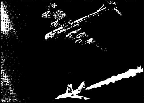
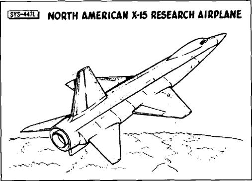
Category Hypersonics Before. the Shuttle

Components and Construction

The X-15 was designed with a hot-structure that could absorb the heat generated by its short-duration flight. Remember, the X-15 seldom flew for over ten minutes at a time, and a much shorter time was spent at the maximum speed or dynamic pressure. Development showed the validity of ground

“partial simulation” testing of primary mem­bers stressed under high temperature. A facility was later built at DFRC for heat – stress testing of the entire structure, and sim­ilar testing was accomplished on the YF-12A

after the X-15. Lockheed also used all-mov­ing surfaces on the Blackbird series of Mach 3 aircraft, although it is difficult to ascertain if the X-15 influenced this design choice.

Blackbird and the Space Shuttle structural test article (STA-099).35

The X-15 pioneered the use of corrugations and beading to relieve thermal expansion stresses. Metals with dissimilar expansion coefficients were also used to alleviate stress­es, and the leading edges were segmented to allow for expansion. Around the same time, similar techniques were apparently developed independently by Lockheed for use on Blackbird series of Mach 3+ aircraft.

The X-15 represented the first large-scale use of Inconel X, in addition to extensive use of titanium alloys. This required the develop­ment of new techniques for forming, milling, drilling, and welding that came to be widely

The X-15 designers also had to solve prob­lems relating to high aerodynamic heating in proximity to cryogenic liquids. This led to cryogenic tubing that was used on parts of the Apollo spacecraft, and thermal insulation design features that were later used on the Space Shuttle. An early experience of run­ning a liquid nitrogen cooling line too close to a hydraulic line taught designers about the need to fully understand the nature of the flu­ids they were dealing with. In-flight failures on high altitude flights with the X-15 also taught aerospace engineers about such things as the need to pressurize gear boxes on aux­iliary power units to prevent foaming of the lubricant in the low pressure of space, since that led to material failures.36

used in the aerospace industry. North American pioneered chemical milling, a construction technique that has since been used on other projects.

The differentially deflected horizontal stabi­lizers on the X-15 provided roll and pitch control and allowed designers to eliminate the ailerons that would have provided a severe structural and theromodynamic prob­lem within the thin wing section used on the X-15. This configuration was already being flight tested by less exotic aircraft (YF-107A) at the same time it was used on the X-15, but nevertheless proved extremely valuable. It is common practice today to use differential stabilators on modem aircraft, particularly fighters, although in most cases conventional ailerons are also retained; the flight control system deciding when to use which control surfaces based on conditions.

The all-moving vertical surfaces in lieu of

Although the primary structure of the X-15 proved sound, several detailed design prob­lems were uncovered during early flight tests. A surprise lesson came with the discovery of heretofore unconsidered local heating phe­nomena. Small slots in the wing leading edge, the abrupt contour change along the canopy, and the wing root caused flow disruptions that produced excessive heating and adjacent material failure. The X-15, tested in “typical” panels or sections, demonstrated the problems encountered when those sections are joined and thus precipitated an analytical program designed to predict such local heating stress­es. From this experience, Rockwell engineers closely scrutinized the segmented carbon-car­bon composite leading edge of the Space Shuttle wing. The bimetallic “floating retain­er” concept designed to dissipate stresses across the X-15’s windshield carried over to the Apollo and Space Shuttle windshield designs as well.

conventional rudders has proven somewhat less attractive to aircraft designers. North American used an all-moving vertical sur­face on the A-5 Vigilante, designed not long

On three occasions, excessive aerodynamic heating of the nose-wheel door scoop caused structural deformation, permitting hot bound­ary-layer air to flow into the wheel well,

Monographs in Aerospace History Number 18 — Hypersonics Before the Shuttle

75

damaging the landing gear, and in one case causing the gear to extend at Mach 4.2 (flight 2-33-56). Although the landing gear remained intact, the disintegration of the tires made the landing very rough. The need for very careful examination of all seals became apparent, and closer scrutiny of surface irreg­ularities, small cracks, and areas of flow interaction became routine. The lessons learned from this influenced the final detailed design of the Space Shuttle to ensure that gaps and panel lines were adequately protect­ed against inadvertent airflow entry.

Other problems from aerodynamic heating included windshield crazing, panel flutter, and skin buckling. Arguably, designers could have prevented these problems through more extensive ground testing and analysis, but a key purpose of flight research is to discover the unexpected. The truly significant lesson from these problems is that defect in subson­ic or supersonic aircraft that are compara­tively minor at slower speeds become much more critical at hypersonic speeds.37

One of the primary concerns during the X-15 development was panel flutter, evidenced by the closing paper presented at the 1956 industry conference. Panel flutter has proven difficult to predict at each speed increment throughout history, and the hypersonic regime was no different. Although the X-15 was conservatively designed, and incorporat­ed all the lessons from first generation super­sonic aircraft, the fuselage side tunnels and the vertical surfaces were prone to develop panel flutter during flight. This led to an industry-wide reevaluation of panel flutter design criteria in 1961-62. Stiffeners and reduced panel sizes alleviated the problems on the X-15, and similar techniques later found general application in the high speed aircraft of the 1960s.’■ The lessons learned at Mach 6 defined criteria later used in the development of the Space Shuttle.

The X-15 provided the first opportunity to study the effects of acoustical fatigue over a wide range of Mach numbers and dynamic pressures. In these first in-flight measure­ments, “boundary layer noise”-related stress­es were found to be a function of g-force, not Mach number. Such fatigue was determined to be no great problem for a structure stressed to normal in-flight loading. This knowledge has allowed for more optimum structural design of missiles and space cap­sules that experience high velocities.

On the X-15, the measurement of velocity was handled by early inertial systems. All three X-15s were initially equipped with analog-type systems which proved to be highly unreliable. Later, two aircraft, includ­ing the X-15-3 with the adaptive control sys­tem, were modified with digital systems. In the subsequent parallel evaluation of analog versus digital inertial systems, the latter was found to be far superior. It was far more flex­ible and could make direct inputs to the adaptive flight control system; it was also subject to less error. Thanks to advances in technology such as laser-ring gyros and dig­ital computers, inertial systems have become inexpensive, highly accurate, and very reli­able.3* In recent years they have been inte­grated with the Global Positioning System (GPS), providing three-dimensional attitude and position information.

During the early test flights, the X-15 relied on simple pilot-static pressure instruments mounted on a typical flight test nose boom. These were not capable of functioning as speeds and altitudes increased. To provide attitude information, the NACA developed the null-sensing “ball-nose” which could survive the thermal environment of the X-15. An extendable pitot tube was added when the velocity envelope was expanded beyond Mach 6. Thus far the ball-nose has not found subsequent application, and probably never will since inertial and GPS systems have evolved so quickly. Interestingly, the Space Shuttle still uses an extendable pitot probe during the landing phase.

The X-15 was the first vehicle to routinely use reaction controls. The HSFS had begun

research on reaction controls in the mid – 1950s using a fixed-base analog control stick with a pilot presentation to determine the effects of control inputs. This was followed by a mechanical simulator to enable the pilot to experience the motions created by reac­tion controls. This device emulated the iner­tial ratios of the X-1B, which incorporated a reaction control system using hydrogen-per­oxide as a monopropellant, decomposed by passing it through a silver-screen catalyst. Because of fatigue cracks later found in the fuel tank of the X-1B, it completed only three flights using the reaction control sys­tem before it was retired in 1958.44

As a result, a JF-104A with a somewhat more refined reaction control system was tested beginning in late 1959 and extending into 1961. The JF-104A flew a zoom-climb maneuver to achieve low dynamic pressures at about 80,000 feet that simulated those at higher altitudes. The techniques for using reaction controls on the X-15, and more importantly, for transferring from aerody­namic controls to reaction controls and back to aerodynamic controls provided a legacy to the space program.41

The X-15-3 was equipped with a Minneapolis Honeywell MH-96 self-adaptive control sys­tem designed for the cancelled Dyna-Soar. The other two X-15s had one controller on the right-hand side of the cockpit for aerodynamic controls and another on the left-hand side for the reaction controls. Thus, the pilot had to use both hands for control during the transition from flying in the atmosphere to flying outside the atmosphere and then back in the opposite direction. Since there was no static stability outside the atmosphere, the pilot had to count­er any induced aircraft motion manually using the reaction controls. The MH-96 had an atti­tude hold feature that maintained the desired attitude except during control inputs. The MH-96 also integrated the aerodynamic and reaction controls in a single controller, greatly improving handling qualities during the transi­tion from aerodynamic to space flight, as well as reducing pilot workload.42

But the basic feature of the MH-96 was auto­matic adjustment of gain (sensitivity) to maintain a desirable dynamic response of the airplane. The MH-96 compared the actual response of the airplane with a preconceived ideal response in terms of yaw, pitch, and roll rates. Initially, Milt Thompson stated that the system was “somewhat unnerving to the pilot” because he was not in “direct control of the aircraft” but was only “commanding a computer that then responded with its own idea of what is necessary in terms of a con­trol output.” However, pilots became “enthu­siastic in their acceptance of it” when they realized that the MH-96 resulted in “more precise command than was possible” with the reaction controls by themselves. Consequently, the X-15-3 with the MH-96 was used for all altitude flights planned above 270,000 feet.4’

There were some problems with the experi­mental system, including one that con­tributed to the death of Mike Adams in X-15- 3 on 15 November 1967. Nevertheless, the MH-96 constituted a significant advance in technology that helped pave the way toward fly-by-wire in the early 1970s. Today, most every aircraft, and several automobiles, fea­ture some variation of a fly-by-wire system with automatic rate-gain adjustment and sta­bility augmentation.44

The Genesis of a Research Airplane

It was not until the mid-1940s that it became apparent to aerodynamic researchers in the United States that it might be possible to build a flight vehicle capable of hypersonic speeds. Until that time, propulsion systems capable of generating the thrust required for such vehi­cles had simply not been considered techni­cally feasible. The large rocket engines that had been developed in Germany during World War II allowed concept studies to be initiated with some hope of success.

Nevertheless, in the immediate post-war peri­od, most researchers believed that hypersonic flight was a domain for unmanned missiles. When an English translation of a technical paper by German scientists Eugen Sanger and Irene Bredt was provided by the U. S. Navy’s Bureau of Aeronautics (BuAer) in 1946, this preconception began to change. Expanding upon ideas conceived as early as 1928, Singer and Bredt had concluded during 1944 that a rocket-powered hypersonic aircraft could be built with only minor advances in technology. The concept of manned aircraft flying at hypersonic speeds was highly stimulating to researchers at the National Advisory Committee for Aeronautics (NACA).’ But although there were numerous paper studies exploring variations of the Sanger and Bredt proposal in the late 1940s, none bore fruit and no hardware construction was undertaken at that time. It was from this background, how­ever, that the concept for a hypersonic research airplane would emerge.2

At the time, there was no established need for a hypersonic aircraft, and it was assumed by many that no operational military3 or civil requirement for hypersonic vehicles would be forthcoming in the foreseeable future. The need for hypersonic research was not over­whelming, but there was a growing body of opinion that it should be undertaken.

The first substantial official support for hyper­sonic research came on 24 June 1952 when the NACA Committee on Aerodynamics passed a resolution to “… increase its program dealing with the problems of unmanned and manned flight in the upper stratosphere at altitudes between 12 and 50 miles,4 and at Mach num­bers between 4 and 10.” This resolution was ratified by the NACA Executive Committee when it met the following month. A study group consisting of Clinton E. Brown (chair­man), William J. O’Sullivan, Jr., and Charles H. Zimmerman was formed on 8 September 1952 at the Langley5 Aeronautical Laboratory. This group endorsed the feasibility of hyper­sonic flight and identified structural heating as the single most important technological prob­lem remaining to be solved.

An October 1953 meeting of the Air Force’s Scientific Advisory Board (SAB) Aircraft Panel provided additional support for hyper­sonic research. Chairman Clarke Millikan released a statement declaring that the feasi­bility of an advanced manned research aircraft “should be looked into.” The panel member from Langley, Robert R. Gilruth, played an important role in coordinating a consensus of opinion between the SAB and the NACA.

Contrary to Sanger’s conclusions, by 1954 it was generally agreed within the NACA and industry that the potential of hypersonic flight could not be realized without major advances in technology. In particular, the unprecedent­ed problems of aerodynamic heating and high-temperature structures appeared to be so formidable that they were viewed as “barriers” to sustained hypersonic flight.

Fortunately, the successes enjoyed by the sec­ond generation X-ls and other high-speed research programs had increased political and philosophical support for a more advanced research aircraft program. The large rocket engines being developed by the long-range missile (ICBM) programs were seen as a way to provide power for a hypersonic research vehicle. It was now agreed that manned hypersonic flight was feasible. Fortunately, at the time there was less emphasis than now on establishing operational requirements prior to conducting basic research, and perhaps even more fortunately, there were no large manned space programs with which to compete for funding. The time was finally right for launch­ing a hypersonic flight research program. s

The specific origins of the hypersonic research program occurred during a meeting of the NACA inter-laboratory Research Airplane Panel held in Washington, DC, on 4­5 February 1954. The panel chairman, Hartley A. Soule, had directed NACA research air­craft activities in the cooperative USAF – NACA program since 1946 and was well versed in the politics and personalities involved. The panel concluded that a wholly new manned research vehicle was needed, and recommended that NACA Headquarters request detailed goals and requirements for such a vehicle from the research laboratories.

In responding to the NACA Headquarters, all of the NACA laboratories set up small ad hoc study groups during March 1954. Langley had been an island of hypersonic study since the end of the war and chose to deal with the problem in more depth than the other labora­tories. After the new 11-inch hypersonic wind tunnel at Langley became operational in 1947, a research group headed by Charles H. McLellan was formed to conduct limited hypersonic research.7 This group, which reported to the Chief of the Langley Aero – Physics Division, John V. Becker, provided verification of newly developed hypersonic theories while investigating such important phenomena as hypersonic shock-boundary – layer interaction. The 11-inch tunnel later served to test preliminary design configura­tions that led to the final hypersonic aircraft configuration. Langley also organized a paral­lel exploratory program into materials and structures optimized for hypersonic flight.

Given this, it was not surprising that a team at Langley was largely responsible for defining the early requirements for the new research airplane. The members of the Langley team included Maxim A. Faget in propulsion; Thomas A. Toll in configuration, stability, and control; Norris F. Dow in structures and mate­rials; and James B. Whitten in piloting. All four fell under the direction of Becker. Besides the almost mandatory elements of stability, control, and piloting, a fourth objective was outlined that would come to dominate virtual­ly every other aspect of the aircraft’s design— it would be optimized for research into the related fields of high-temperature aerodynam­ics and high-temperature structures. Thus it would become the first aircraft in which aero – thermo-structural considerations constituted the primary research problem, as well as the primary research objective.

The preliminary specifications for the research aircraft were surprisingly brief: only four pages of requirements, plus six addition­al pages of supporting data. A new sense of urgency was present: “As the need for the exploratory data is acute because of the rapid advance of the performance of service air­craft, the minimum practical and reliable air­plane is required in order that the develop­ment and construction time be kept to a mini­mum."* In other versions of the requirements this was made even more specific: “It shall be possible to design and construct the airplane within 3 years.”9 As John Becker subsequent­ly observed, "… it was obviously impossible that the proposed aircraft be in any sense an optimum hypersonic configuration.”

In developing the general requirements, the team developed a conceptual research aircraft that served as a model for the eventual X-15. The aircraft they conceived was “… not pro­posed as a prototype of any of the particular

The first Bell X-2 (46-674) made its ini­tial unpowered glide flight on 5 August 1954. This aircraft made a total of 17 flights before it was lost on 27 September 1956. Its pilot, Air Force Captain Milburn Apt had flown to a record speed 2,094 mph, thereby becom­ing the first person to exceed Mach 3.

The Genesis of a Research Airplane(NASA/DFRC)

concepts in vogue in 1954 … [but] rather as a general tool for manned hypersonic flight research, able to penetrate the new regime briefly, safely, and without the burdens, restrictions, and delays imposed by opera­tional requirements other than research.” The merits of this approach had been convincing­ly demonstrated by the successes of the X-l and other dedicated research aircraft of the late 1940s and early 1950s.10

Assuming that the new vehicle would be air launched like the X-l and X-2, Langley estab­lished an aircraft size that could conveniently be carried by a Convair B-36, the largest suit­able aircraft available in the inventory. This translated to a gross weight of approximately

30.0 pounds, including 18,000 pounds of fuel and instrumentation.11 A maximum speed of 4,600 mph and an altitude potential of

400.0 feet were envisioned, with the pilot subjected to approximately 4.5g (an accelera­tion equal to 4.5 times the force of gravity) at engine burnout.12

The proposed maximum speed was more than double that achieved by the X-2, and placed the aircraft in a region where heating was the
primary problem associated with structural design, and where very little background information existed. Hypersonic aerodynam­ics was in its infancy in 1954. The few small hypersonic wind tunnels then in existence had been used almost exclusively for fluid mechanics studies, and they were unable to simulate either the high temperatures or the high Reynolds numbers of actual flight. It was generally believed that these wind tunnels did not produce valid results when applied to a full-scale aircraft. The proposed hypersonic research airplane, it was assumed, would pro­vide a bridge over the huge technological gap that appeared to exist between laboratory experimentation and actual flight.12

One aspect of the Langley proposal caused considerable controversy. The Langley team called for two distinct research flight profiles. The first consisted of a variety of constant angle-of-attack, constant altitude, and maneu­vering flights to investigate the aerodynamic and thermodynamic characteristics and limi­tations of then-available technology. These were the essential hypersonic research flights. But the second flight profile was designed to explore some of the problems of manned

space flight by making "… long leaps out of the sensible atmosphere.” This included inves­tigations into high-lift and low-L/D (lift over drag; commonly called a drag coeffi­cient) during the reentry pull-up maneuver” which was recognized as a prime problem for manned space flight from both a heating and piloting perspective.14

This brought other concerns: “.., As the speed increases, an increasingly large portion of the aircraft’s weight is borne by centrifugal force until, at satellite velocity, no aerodynamic lift is needed and the aircraft may be operated completely out of the atmosphere. At these speeds the pilot must be able to function for long periods in a weightless condition, which is of considerable concern from the aeromed – ical standpoint.” By employing a high altitude ballistic trajectory to approximately 250,000 feet, the Langley group expected the pilot would operate in an essentially weightless condition for approximately two minutes. Attitude control was another problem, since traditional aerodynamic control surfaces would be useless at the altitudes proposed for the new aircraft; the dynamic pressure would be less than 1 pound per square foot (psf). The
use of small hydrogen-peroxide thrusters for attitude control was proposed.

While the hypersonic research aspect of the Langley proposal enjoyed virtually unani­mous support, it is interesting to note that the space flight aspect was viewed in 1954 with what can best be described as cautious toler­ance. There were few who believed that any space flight was imminent, and most believed that manned space flight in particular was many decades in the future, probably not until the 21st century. Several researchers recom­mended that the space flight research was pre­mature and should be removed from the рто – gram. Fortunately, it remained.15

Hypersonic stability was the first problem of really major proportion encountered in the study. Serious instability had already been encountered with the X-l and X-2 at Mach numbers substantially lower than those expected with the proposed hypersonic research aircraft, and it was considered a major challenge to create a solution that would permit stable flight at Mach 7.

Researchers at Langley discovered through

Подпись:Подпись:The Genesis of a Research AirplaneThe notional research airplane designed by John V. Becker’s group at Langley shows the basis for the eventual X-15. Note the bullet­shaped fuselage (similar to the X-1) and the configuration of the empennage. This was the shape most of the early wind tunnel and analytical studies were per­formed against. (NASA)

wind tunnel testing and evaluating high speed data from earlier X-planes that an extremely large vertical stabilizer was required if the thin sections then in vogue for supersonic aircraft were used. This was largely because of a rapid loss in the lift-curve slope of thin sections as the Mach number increased. The solution devised by McLellan, based on theoretical considerations of the influence of airfoil shape on normal force characteristics, was to replace the thin supersonic-airfoil section of the vertical stabilizer with a 10 degree wedge shape. Further, a variable-wedge vertical sta­bilizer was proposed as a means of restoring the lift-curve slope at high speeds, thus per­mitting much smaller surfaces, which were easier to design structurally and imposed a smaller drag penalty on the airframe. McLellan’s calculations indicated that this wedge shape should eliminate the disastrous directional stability decay encountered by the X-l and X-2.

edge, very similar to the one eventually used on the Space Shuttle orbiters. Both the brak­ing effect and the stability derivatives could be varied through wide ranges by variable deflection of the wedge surfaces. The flexibil­ity made possible by variable wedge deflec­tion was thought to be of great value because a primary use of the airplane would be to study stability, control, and handling charac­teristics through a wide range of speeds and altitudes. lfi

Two basic structural design approaches had been debated since the initiation of the study—first, a conventional low-temperature design of aluminum or stainless steel protect­ed from the high-temperature environment by a layer of assumed insulation; and second, an exposed hot-structure in which no attempt would be made to provide protection, but in which the metal used and the design approach would permit high structural temperatures.17

Becker’s group also included speed brakes as part of the vertical stabilizers to reduce the Mach number and heating during reentry. Interestingly, the speed brakes originally pro­posed by Langley consisted of a split trailing

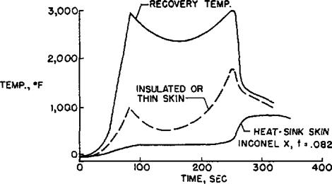
It was found from analysis of the heating pro­jections for various trajectories that the air­plane would need to accommodate tempera­tures of over 2,000 degrees Fahrenheit on the lower surface of the wing. At the time, there

This chart was used by Becker to demon­strate the relative dif­ferences between the nominal recovery tem­perature, compared to the temperatures expected to be sus­tained by an insulated structure and an appropriately designed heat-sink skin (hot-structure). Inconel X was the material of choice very early in the study.

Подпись: TYPICAL TEMPERATURE HISTORY DESIGN ALTITUDE FLIGHT LOWER SURFACE, xMFT The Genesis of a Research Airplane(NASA)

was no known insulating technique that could meet this requirement. The Bell “double­wall” concept where a non Toad-bearing metal sandwich acted as the basic insulator, would later undergo extensive development, but in 1954, it was in an embryonic state and not applicable to the critical nose and leading edge regions. Furthermore, it required a heavy and space-consuming supplemental liquid cooling system. However, the study group felt that the possibility of local failure of any insu­lation scheme constituted a serious hazard. Finally, the problem of accurately measuring heat-transfer rates—one of the prime objec­tives of the new research aircraft program— would be substantially more difficult to accomplish with an insulated structure.

At the start of the study it was by no means obvious that the hot-structure approach would prove practical either. The permissible design temperature for the best available material was about 1,200 degrees Fahrenheit, which was far below the estimated equilibrium temperature peak of about 2,000 degrees Fahrenheit. It was clear that some form of heat dissipation would have to be employed—either direct internal cooling or heat absorption into the structure
itself. It was felt that either solution would bring a heavy weight penalty.

The availability of Inconel Xі* and its excep­tional strength at extremely high temperatures, made it, almost by default, the structural mate­rial preferred by Langley for a hot-structure design. During mid-1954, an analysis of an Inconel X structure was begun by Becker’s group; concurrently, a detailed thermal analy­sis was conducted. A subsequent stress study indicated that the wing skin thickness should range from 0.05 to 0.10 inches—about the same values found necessary for heat absorp­tion in the thermal analysis.

Thus it was possible to solve the structural problem for the transient conditions of a Mach 7 aircraft with no serious weight penal­ty for heat absorption. This was an unexpect­ed plus for the hot-structure. Together with the fact that none of the perceived difficulties of an insulated-type structure were present, the study group decided in favor of an uninsulat­ed hot-structure design.

Unfortunately, it later proved that the hot – structure had problems of its own, particularly
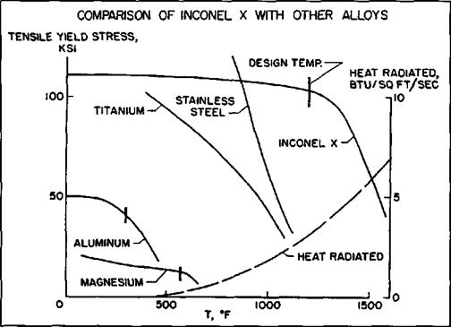
The Genesis of a Research AirplaneInconel X was easily the best high-tempera­ture alloy available during the 1950s. It possessed a rare combination of high tensile strength and the ability to withstand high temperatures. Although it proved somewhat difficult to work with, it did not impose some of the problems encountered with titanium on other high-speed aircraft projects. (NASA)

in the area of nonuniform temperature distri­bution. Detailed thermal analyses revealed that large temperature differences would develop between the upper and lower wing skin during the pull-up portions of certain tra­jectories. This unequal heating would result in intolerable thermal stresses in a conventional structural design. To solve this new problem, wing shear members were devised which did not offer any resistance to unequal expansion of the wing skins. The wing thus was essen­tially free to deform both spanwise and chord – wise with asymmetrical heating. Although this technique solved the problem of the gross thermal stresses, localized thermal-stress problems still existed in the vicinity of the stringer attachments. The study indicated, however, that proper selection of stringer pro­portions and spacing would produce an acceptable design free from thermal buckling.

During the Langley studies, it was discovered that differential heating of the wing leading edge produced changes in the natural torsion­al frequency of the wing unless some sort of flexible expansion joint was incorporated in its design. The hot leading edge expanded faster than the remaining structure, introduc­ing a compression that destabilized the sec­tion as a whole and reduced its torsional stiff­ness, To negate this phenomenon, the leading edge was segmented and flexibly mounted in an attempt to reduce thermally induced buck­ling and bending.

With its research objectives and structure now essentially determined, the Langley team turned its attention to the questions of propulsion by examining various existing rocket propulsion systems. The most promis­ing configuration was found to be a grouping of four General Electric A1 or A3 Hermes rocket engines, due primarily to the “thrust stepping” (a crude method of modulating, or throttling, the thrust output) option this con­figuration provided.

The studies prompted the NACA to adopt the official policy that the construction of a manned hypersonic research airplane was fea­sible. In June 1954, Dr. Hugh L. Dryden sent a letter to Lieutenant General Donald Putt at Air Force Headquarters stating that the NACA was interested in the creation of a new manned research aircraft program that would explore hypersonic speeds and altitudes well in excess of those presently being achieved. The letter also recommended that a meeting between the NACA, Air Force Headquarters, and the Air Force SAB be arranged to discuss the project. Putt responded favorably, and also recom­mended that the Navy be invited to participate.

NACA representatives met with members of the Air Force and Navy research and develop­ment groups on 9 July 1954 to present the proposal for a hypersonic research aircraft as an extension of the existing cooperative research airplane program. It was soon dis­covered that the Air Force SAB had been making similar proposals to Air Force Headquarters, and that the Office of Naval Research had already contracted with the Douglas Aircraft Company to determine the feasibility of constructing a manned aircraft capable of achieving 1,000,000 feet altitude. Douglas had concluded that 700,000 foot alti­tudes would be possible from the reentry deceleration standpoint, but that the thermo­structural problem had not been thoroughly analyzed. It was agreed that a cooperative pro­gram would be more cost effective and likely lead to better research data at an earlier time.19

The Navy and Air Force representatives viewed the NACA proposal with favor, although each had some reservations. At the close of the meeting, however, there was agreement that both services would further study the details of the NACA proposal, and that the NACA would take the initiative to secure project approval from the Department of Defense.2"

Less than a month later, the Air Force identi­fied the principal shortcoming of the original Langley proposal—the apparent lack of a suitable rocket engine. In early August the Power Plant Laboratory at the Wright Air Development Center (WADC) pointed out

that “no current rocket engines” entirely satis­fied the NACA requirements, and emphasized that the Hermes engine was not designed to be operated in close proximity to humans—that it usually was fired only when shielded by concrete walls. Other major objections to the Hermes engine centered around its relatively early state of development, its limited design life (intended for missile use, it was not required to operate successfully more than once), and the apparent difficulty of incorpo­rating the ability to throttle it during flight.21 WADC technical personnel who visited Langley on 9 August drew a firm distinction between engines intended for piloted aircraft and those designed for missiles; the NACA immediately recognized the problem, but con­cluded that although program costs would increase, the initial feasibility estimates would not be affected.22

WADC’s official reaction to the NACA pro­posal was submitted to the Air Research and Development Command (ARDC) on 13 August.2’ Colonel V. R. Haugen reported “unanimous” agreement among WADC par­ticipants that the proposal was technically fea­sible; excepting the engine situation, there was no occasion for adverse comment. The evaluation forwarded by Haugen also con­tained a cost estimate of $12,200,000 “distrib­uted over three to four fiscal years" for two research aircraft and necessary government – furnished equipment. Estimated costs includ­ed: $1,500,000 for design work; $9,500,000 for construction and development, including flight test demonstration; $650,000 for gov­ernment furnished equipment, including engines, $300,000 for design studies and specifications; and $250,000 for modification of a carrier aircraft.24 Somewhat prophetically, one WADC official commented informally: “Remember the X-3, the X-5, [and] the X-2 overran 200 percent. This project won’t get started for $12,000,000.”"

On 13 September, the ARDC issued an endorsement of the NACA proposal, and rec­ommended that the Air Force “… initiate a project to design, construct, and operate a new research aircraft similar to that suggested by NACA without delay.” The aircraft, empha­sized ARDC, should be considered a pure research vehicle and should not be pro­grammed as a weapon system prototype. On 4 October 1954, Brigadier General Benjamin S. Kelsey, Deputy Director of Research and Development at Air Force Headquarters, stat­ed that the project would be a joint Navy – NACA-USAF effort managed by the Air Force and guided by a joint steering commit­tee. Air Force Headquarters further pointed out the necessity for funding a special flight test range as part of the project:4′

The NACA Committee on Aeronautics met on 5 October 1954 to consider the hypersonic research aircraft. During the meeting, historic and technical data were reviewed by various committee members including Walter C. Williams, De E. Beeler, and research pilot A. Scott Crossfield from the High-Speed Flight Station (HSFS). Williams’ support was cru­cial. Crossfield would later describe Williams as.. the man of the 20th Century who made more U. S. advanced aeronautical and space programs succeed than all the others together. … He had no peer. None. He was a very strong influence in getting the X-15 program launched in the right direction.”27

Although one Committee member expressed opposition to the proposed hypersonic research aircraft as an extension to the on­going test programs, the rest of the Committee supported the project. The Committee formal­ly adopted a resolution to build a Mach 7 research airplane (attached as an appendix to this monograph).2*

Because the anticipated cost of the project would require support from Department of Defense contingency funds as well as Air Force and Navy R&D funds, a formal Memorandum of Understanding (MoU) was drafted and sent around for signatures begin­ning in early November 1954. The MoU was originated by Trevor Gardner (Air Force Special Assistant for Research and Development), and was forwarded, respec-

tively, for the signatures of J. H. Smith Jr. H (Assistant Secretary of the Navy [Air]) and Hugh L. Dryden (Director of the NACA). Dryden signed the Moll on 23 December 1954, and returned executed copies to the Air Force and Navy.’0

The MoU (attached as an appendix to this monograph) provided that technical direction of the research project would be the responsi­bility of the NACA, acting.. with the advice and assistance of a Research Airplane Committee” composed of one representative each from the Air Force, Navy, and the NACA. Administration of the design and construction phases of the project was assigned to the Air Force. The NACA would conduct the flight research, with extensive support from the Air Force Flight Test Center. The Navy was essen­tially left paying 25 percent of the bills with little active roll in the project, although it would later supply biomedical expertise and a single pilot. The NACA and the Research Airplane Committee were charged with the responsibility for disseminating the research results to the military services and aircraft industry as appropriate based on various secu­rity aspects. The concluding statement on the MoU was: “Accomplishment of this project is a matter of national urgency.’’11

It should be noted that it was not unusual in the late 1940s and early 1950s for the military services to fund the development and con­struction of aircraft for the NACA to use in its flight test programs. This was how most of the testing on the X-l and others had been accom­plished. The eventual X-l5 would be the fastest, highest-flying, and most expensive of these joint projects.12

After the signed copies of the MoU were returned to all participants, the Department of Defense authorized the Air Force to issue invitations to contractors having experience in the development of fighter-type aircraft to participate in the design competition. After the Christmas holidays, on 30 December, the Air Force sent invitation-to-bid letters to 12 prospective contractors; Bell, Boeing,

Chance-Vought, Consolidated (Convair), Douglas, Grumman, Lockheed, Martin, McDonnell, North American, Northrop, and Republic. The letter asked those interested in bidding to notify Wright Field by 10 January 1955, and to attend a bidder’s conference on 18 January 1955.”

Attached to the letter were a preliminary out­line specification, an abstract of the Langley preliminary study, a discussion of possible engines, a list of data requirements, and a cost outline statement. Each bidder was required to satisfy various requirements set forth, except in the case of the NACA abstract which was presented as "… representative of possible solutions.”14

Grumman, Lockheed, and Martin expressed little interest in the competition and did not attend the bidder’s conference, leaving nine possible competitors. At the bidders’ confer­ence, representatives from the contractors met with NACA and Air Force personnel to discuss the competition and the basic design requirements.

During the bidders’ conference, the airframe manufacturers were informed that one prime proposal and one alternate proposal (that might offer an unconventional but superior solution to the problems involved) would be accepted from each company. It also was noted that an engineering study, only, would be required for a modified aircraft where an observer could be substituted for the research instrumentation (a Navy require­ment); that a weight allowance of 800 pounds, a volume of 40 cubic feet, and a power requirement of 2.25 kilowatts (kW) needed to be provided for research instru­mentation; and that the winning design would have to be built in 30 months and be capable of attaining speeds of Mach 6 and altitudes of 250,000 feet. Following the pre­liminary statements concerning the bidding, NACA personnel briefed the various compa­nies in attendance on new information that had resulted from late 1954 wind tunnel research that had taken place at Langley.

Subsequently, between the bidders’ confer­ence and the 9 May submission deadline, Boeing, Chance-Vought, Convair, Grumman, McDonnell, and Northrop notified the Air Force that they did not intend to submit for­mal proposals. This left Bell, Douglas, North American, and Republic. During this period, representatives from these companies met with NACA personnel on numerous occa­sions and reviewed technical information on various aspects of the forthcoming research airplane. The NACA also provided these con­tractors with further information gained as a result of wind tunnel tests in the Ames 10-by – 14 inch supersonic tunnel and the Langley Mach 4 blowdown tunnel.

On 17 January 1955, NACA representatives met with Air Force personnel at Wright Field and were informed that the research airplane was identified as Air Force Project 1226 and would be officially designated X-15.

The Power Plant Laboratory had originally listed the Aerojet XLR73, Bell XLR81, North American NA-5400 (an engine in early devel­opment, still lacking a military designation), and the Reaction Motors XLR10 (and its vari­ants, including the XLR30) as engines that the airframe competitors could use in their designs. Early in January, the laboratory had become concerned that the builders of engines other than those listed might protest the exclu­sion of their products. Consequently there emerged an explanation and justification of the engine selection process. It appeared that the engineers had confidence in the ability of the XLR81 and XLR73 to meet airplane require­ments, had doubts about the suitability of the XLR25 (a Curtiss-Wright product), and held the thrust potential of the XLR8 and XLR11 (similar engines) in low repute. For practical purposes, this exhausted the available Air Force-developed engines suitable for manned aircraft. The XLR10 and NA-5400 were the only Navy-developed engines viewed as acceptable in terms of the competition.35

Earlier, the engine manufacturers had been contacted for specific information about the engines originally listed as suitable for the X-15 program,36 and this information was dis­tributed to all four prospective airframe con­tractors.37 Due to its early development status, there was little data available for the North American NA-5400, and the Reaction Motors XLR10 was “not recommended” at the sug­gestion of the engine manufacturer itself. On 4 February each of the prospective engine contractors (Aerojet, Bell, North American, and Reaction Motors) was asked to submit an engine development proposal.38 Based on this, the Air Force very slightly relaxed the rigid limitations on engine selection, instructing competitors that.. if… an engine not on the approved list offers sufficient advantage, the airframe company may, together with the engine manufacturer, present justification for approval…” to the Air Force.35

On 9 May 1955, Bell, Douglas, North American, and Republic submitted their pro­posals to the Air Force. Two days later the technical data was distributed to the evaluation groups with a request that results be returned by 22 June.40 The final evaluation meeting was scheduled for 25 July at Wright Field.41

Shortly thereafter, Hartley A. Soule, as Chairman of the NACA evaluation group, sent the evaluation rules and processes to the NACA laboratories. The evaluation would be based on the technical and manufacturing competency of each contractor, schedule and cost estimates, design approach, and the research utility of each design. In order to expedite the evaluation, each of the NACA laboratories was assigned specific items to consider with responses to be returned to Soule no later than 13 June.

The evaluation of the engine would be made at the same time, but would be conducted sep­arate from that of the airframe contractor, with the possibility that the chosen engine might not be the one selected by the winning air­frame contractor.

On 10 June the HSFS results were sent to Soule, based on the design approach and

research utility aspects of the airframe, flight control system, propulsion unit, crew provi­sions, handling and launching, and miscella­neous systems. The proposals were ranked:

(1) Douglas; (2) North American; (3) Bell; and (4) Republic. The proposals from Douglas and North American were consid­ered almost equal on the basis of points.

The Ames final evaluation, on 13 June 1955, ranked the proposals: fl) North American;

(2) Douglas; (3) Bell; and (4) Republic. The North American structure was considered to be more representative of future aircraft and thus superior in terms of research utility. Douglas retained a simple and conventional magnesium structure, but in so doing avoided the very thermodynamic problems the research effort wished to explore.

The 14 June final evaluation from Langley ranked the proposals; (1) North American; (2) Douglas; (3) Republic; and (4) Bell. Langley felt that while the magnesium wing structure of Douglas was feasible, it was feared that local hot spots caused by irregular aerody­namic heating could weaken the structure and be subject to failure. North American’s use of Inconel X was believed to be an advantage.

The final order representing the overall NACA evaluation was (1) North American; (2) Douglas; (3) Bell; and (4) Republic. All of the laboratories involved in this portion of the evaluation considered both the North American and Douglas proposals to be much superior to those submitted by Bell and Republic.

As with the NACA evaluations, the Air Force found little difference between the Douglas and North American designs, point-wise, with both proposals significantly superior to those of Beil and Republic. The Navy evaluation found much the same thing, ranking the pro­posals: (1) Douglas; (2) North American; (3) Republic; and (4) Bell.

On 26-28 July, the Air Force, Navy, and NACA evaluation teams met to coordinate their separate results. The Air Force and the NACA concluded that the North American proposal best accommodated their require­ments. Accordingly, the Navy decided not to. be put in the position of casting the dissenting vote and after short deliberation, agreed to go along with the decision of the Air Force and the NACA. A combined meeting of the Air Force, Navy, and the NACA was held at NACA Fleadquarters on 12 August for the final briefing on the evaluation. Later, the Research Airplane Committee met, accepted the findings of the evaluation groups, and agreed to present the recommendation to the Department of Defense.

Interestingly, the North American proposal was by far the most expensive. The estimat­ed costs for three aircraft plus one static test article and supporting equipment were: Bell, $36.3 million; Douglas, $36.4 million; Republic, $47 million; and North American, $56.1 million.

Because the estimated costs submitted by North American were far – above the amount allocated for the project, the Research Airplane Committee included a recommenda­tion for a funding increase that would need to be approved before the actual contract was signed. A further recommendation, one that would later take on greater importance, called for relaxing the proposed schedule by up to one-and-one-half years. These recommenda­tions were sent to the Assistant Secretary of Defense for Research and Development.

Events took an unexpected twist on 23 August when the North American represen­tative in Dayton verbally informed the Air Force that the company wished to withdraw its proposal. On 30 August, North American sent a letter to the Air Force formally requesting that the company be allowed to withdraw from consideration.43

The Vice President and Chief Engineer for North American, Raymond H. Rice, wrote to the Air Force on 23 September and explained that the company had decided to withdraw

C


from the competition because it had recently won new bomber and long range interceptor competitions and also had increased activity relating to its on-going F-107 fighter. Having undertaken these projects, North American said it would be unable to accommodate the fast engineering man-hours build-up that would be required to support the desired schedule. Rice went on that, “… due to the apparent interest that has subsequently been expressed in the North American design, the contractor [North American] wishes to extend two alternate courses which have been previ­ously discussed with Air Force personnel: The engineering man-power work load schedule has been reviewed and the contractor wishes to point out that Project 1226 could be han­dled if it were permissible to extend the schedule… over an additional eight month period: in the event the above time extension is not acceptable and in the best interest of the project, the contractor is willing to release the proposal data to the Air Force at no cost.”43

As it turned out, the possibility of extending the schedule had already been approved on 12 August, allowing North American to with­draw its previous letter of retraction once it had been officially informed that it had won the contract.44 Accordingly, on 30 September 1955, the Air Force formally notified North American that its design had been selected as the winner. The other bidders were conse­quently notified of North American’s selec­tion and thanked for their participation.45

By 11 October, the estimate from North American had been reduced from $56,000,000 to $45,000,000 and the maxi­mum annual funds requirement from $26,000,000 to $15,000,000. Shortly there­after, the Department of Defense released the funds needed to start work. More meetings between the Air Force, the NACA, and North American were held on 27-28 October, large­ly to define changes to the aircraft configura­tion. On 18 November, letter contract AF33(600)-31693 was sent to North American, and an executed copy was returned on 8 December 1955.46 The detailed design
and development of the hypersonic research airplane had been underway for just under a year at this point.47

On 1 December 1955, a series of actions48 began that resulted in letter contract AF33(600)-32248 being sent to Reaction Motors, effective on 14 February 1956. Its ini­tial allocation of funds totaled $3,000,000, with an eventual expenditure of about $6,000,000 foreseen as necessary for the delivery of the first flight engine.49

A definitive contract for North American was completed on 11 June 1956, superseding the letter contract and two intervening amend­ments. At that time, $5,315,000 had been committed to North American. The definitive contract allowed the eventual expenditure of $40,263,709 plus a fee of $2,617,075. For this sum, the government was to receive three X-15 research aircraft, a high speed and a low speed wind tunnel model program, a free-spin model, a full-size mockup, propulsion system tests and stands, flight tests, modification of a B-36 carrier aircraft, a flight handbook, a maintenance handbook, technical data, peri­odic reports of several types, ground handling dollies, spare parts, and ground support equip­ment. Exclusive of contract costs were fuel and oil, special test site facilities, and expens­es to operate the B-36. The delivery date for the X-15s was to be 31 October 1958. The quantity of aircraft had been determined by experience; it had been noted during earlier research aircraft programs that two aircraft were enough to handle the anticipated work­load, but three assured that the test pace could be maintained even with one aircraft down.50 This lesson has been largely forgotten in our current budget-conscious era.

A final contract for the engine, the prime unit of government furnished equipment, was effective on 7 September 1956. Superseding the letter contract of February, it covered the expenditure of $10,160,030 plus a fee of $614,000.51 For this sum, Reaction Motors agreed to deliver one engine, a mockup, reports, drawings, and tools.

Hypersonic Research Engine

With little doubt, the most ambitious47 of the

X-15 experiments was the Hypersonic Research Engine (HRE) from the Langley Research Center. At the time that researchers began to consider supersonic-combustion ramjet engines during 1954, the X-15 was not an approved program and played no major role in the engine’s conceptual development. However, events soon transpired that made flight testing of a supersonic ramjet engine desirable, and the Flight Research Center and Langley proposed a joint project to accom­plish just that. The 1962 crash of the X-15-2 opened the door for extensive modification aimed primarily at providing a platform for development of the Mach 8 air-breathing HRE. Then, as now, no tunnel facility existed wherein such an engine could be realistically tested, and rocket boosters could not give steady-state tests or return the equipment.48

The actual prototype engine was to be carried attached to the lower ventral of the X-15A-2. Twenty-nine inches were added to the fuse­lage between the existing tanks for the liquid hydrogen to power the HRE, two external fuel tanks were added, and the entire aircraft was coated with an ablative-type insulator.

During 1965, Garrett-AirResearch was put under contract to provide six prototype engines by mid-1969. As would happen, the development effort necessary to produce a workable engine had been severely underesti­mated, and Garrett quickly ran into problems that caused serious delays in the project.

In the meantime flight-test evaluations were made of the modified aircraft itself and of a dummy HRE attached to the X-15A-2. On the first and only maximum-speed test of the X-15 A-2 in 1967, shock impingement off the dummy HRE caused severe heating damage to the lower empennage, and very nearly resulted in loss of the aircraft. Though quick­ly repaired, the X-15A-2 never flew again. Hindsight would place the blame for this design oversight on haste and insufficient flow interaction studies. A key lesson learned from this episode was not to hang external stores or pylons on hypersonic air-

craft, at least not without far more extensive study of underside flow patterns. As John Becker later observed, “Flight testing on the X-15A-2 would have been long-delayed, hazardous, very costly, and fortunately never came about.”4V

When the X-15 flight program was terminat­ed, the HRE degenerated into a costly wind tunnel program using partial-simulation test models. The HRE was eventually tunnel test­ed in 1969, and the primary objective of achieving supersonic combustion was met, although the thrust produced was less than the drag created. HRE engineers nonetheless claim a success in that the objective was supersonic combustion, not a workable engine. The program continued until 1975 and never achieved a positive net thrust, although it still contributed to the technology base, albeit at a very high cost. A hindsight study conducted in 1976 concluded that the HRE’s fuel-cooled structure was its main contribution to future scramjets.50

X-15 Design and Development

Harrison A. “Stormy” Storms, Jr. led the North American X-15 design team, along with project engineer Charles H. Feltz. These two had a difficult job ahead of them, for although giving the appearance of having a rather sim­ple configuration, the X-15 was perhaps the most technologically complex single-seat air­craft of its day. Directly assisting Storms and Feltz was test pilot A. Scott Crossfield, who had worked for the NACA prior to joining North American with the intended purpose of working on the X-15 program. Crossfield describes Storms as a man of wonderful imagination, technical depth, and courage… with a love affair with the X-15. He was a tremendous ally and kept the objectivity of the program intact….” According to Crossfield, Feltz was a remarkable ‘can do and did’ engineer who was very much a source of the X-15 success story.”1

Storms himself remembers his first verbal instructions from Hartley Sould: “You have a little airplane and a big engine with a large thrust margin. We want to go to 250,000 feet altitude and Mach 6. We want to study aero­dynamic heating. We do not want to worry about aerodynamic stability and control, or the airplane breaking up. So if you make any errors, make them on the strong side. You should have enough thrust to do the job.” Adds Storms, “and so we did.”2

Crossfield’s X-15 input proved particularly noteworthy during the early days of the development program as his experience per­mitted the generation of logical arguments that led to major improvements to the X-15. He played a key role, for instance, in con­vincing the Air Force that an encapsulated ejection system was both impractical and

X-15 Design and DevelopmentBy the time of the first industry conference in 1956, this was the design baseline for the North American X-15. Note the tall ver­tical stabilizer, and the fact that it does not have the distinctive wedge shape of the final unit. Also notice how far forward the fuselage tunnels extend—well past the canopy. (NASA)
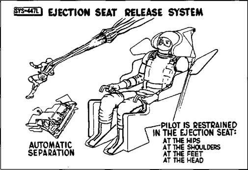
unnecessary. His arguments in favor of an ejection seat, capable of permitting safe emergency egress at speeds between 80 mph and Mach 4 and altitudes from sea level to 120,000 feet, saved significant money, weight, and development time.

There has been considerable interest over whether Crossfield made the right decision in leaving the NACA since it effectively locked him out of the high-speed, high-alti­tude portion of the X-15 flight program. Crossfield has no regrets: “… I made the right decision to go to North American. I am an engineer, aerodynamicist, and designer by training… While I would very much have liked to participate in the flight research pro­gram, I am pretty well convinced that f was needed to supply a lot of the impetus that allowed the program to succeed in timeli­ness, in resources, and in technical return…. I was on the program for nine years from conception to closing the circle in flight test. Every step: concept, criteria, requirements, performance specifications, detailed specifi­cations, manufacturing, quality control, and flight operations had all become an [obses­sion] to fight for, protect, and share—almost with a passion.”3

Although the first, and perhaps the most influential pilot to contribute to the X-15 program, Crossfield was not the only one to do so. In fact, all of the initially assigned X-15 pilots participated in the development phases, being called on to evaluate various operational systems and approaches, as well as such factors as cockpit layout, control sys­tems, and guidance schemes. They worked jointly with engineers in conducting the sim­ulator programs designed to study the aspects of planned flight missions believed to present potential difficulties. A fixed – base simulator was developed at North American’s Los Angeles facility, containing a working X-15 cockpit and control system that included actual hydraulic and control – system hardware. Following use at North American, it was subsequently relocated to the Flight Research Center4 (FRC) at Edwards AFB. Once flight research began, the simulator was constantly refined with the results of the flight test program, and late in its life the original analog computers were replaced by much faster digital units. For the life of the program, every X-15 flight was preceded by 10-20 hours in the simulator.

A ground simulation of the dynamic envi-

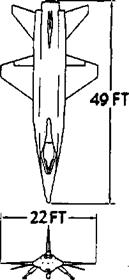
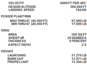
I2S2Q THREE VIEW


X-15 Design and DevelopmentПодпись:Подпись: VELOCITY 6600 FT PER SEC DESIGN ALTITUDE 260,000 FT LANDING SPEED 164 KN POWER PLANT*RMl MAX THRUST (40.000 FT) 57,000 LB MIN THRUST (40,000 FT) 17,000 LB WING AREA 200 SQ FT SWEEP c/4 25 0E6BEES THICKNESS 5 PERCENT ASPECT RATIO 2.5 WEIGHT LAUNCHING 31.275 LB BURN-OUT 12.971 LB PROPELLANT 13.304 LB X-15 Design and DevelopmentOne of the more con­troversial features of the North American design was the fuse­lage tunnels that car­ried the propellant lines and engine con­trols around the full monocoque propellant tanks, shown in this 1956 sketch. Originally these tunnels extend­ed forward ahead of the cockpit, and the NACA worried they would create unac­ceptable vortices. (NASA)

ronment was provided by use of the Navy centrifuge at the Naval Air Development Center (NADC) Johnsville, Pennsylvania. Over 400 simulated reentries5 were flown during an initial round of tests completed on 12 July 1958; Iven Kincheloe, Joe Walker, Scott Crossfield, A1 White, Robert White, Neil Armstrong, and Jack McKay participat­ed. The primary objective of the program was to assess the pilot’s ability to make emergency reentries under high dynamic conditions following a failure of the stability augmentation system. The results were gen­erally encouraging.6

When the contracts with North American had been signed, the X-15 was some three years away from actual flight test. Although most of the basic research into materials and structural science had been completed, a great deal of work remained to be accom­plished. This included the development of fabrication and assembly techniques for Inconel X and the new hot-structure design. North American met the challenge of each problem with a practical solution, and even­tually some 2,000,000 engineering man­hours and 4,000 wind tunnel hours in 13 dif­ferent wind tunnels were logged.

The original North American proposal gave rise to several questions which prompted a meeting at Wright-Patterson AFB on 24-25 October 1955. Subsequent meetings were held at the North American Inglewood plant on 28-29 October and 14-15 November. Major discussion items included North American’s use of fuselage tunnels and all­moving horizontal stabilizers (the “rolling – tail”). The rolling-tail operated differentially to provide roll control, and symmetrically to provide pitch control; this allowed the elimi­nation of conventional ailerons. North American had gained considerable experi­ence with all-moving control surfaces on the YF-107A fighter. In this instance the use of differentially operated surfaces simplified the construction of the wing, and allowed elimination of protuberances that would have been necessary if aileron actuators had been incorporated in the thin wing. Such pro­tuberances would have disturbed the airflow and created another heating problem.

One other significant difference between the configuration of the NACA design and that of the actual X-15 stemmed from North American’s use of full-monocoque propel­lant tanks in the center fuselage and the use

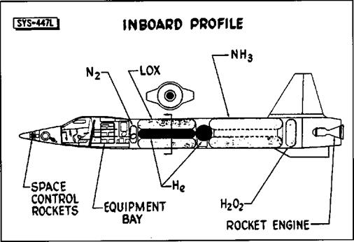
The interior layout of the fuselage did not change much after the 1956 conference. Note the helium tank locat­ed in the middle of the LOX tank. The hydro­gen-peroxide (H202) was used to power the turbopump on the XLR99 rocket engine.

X-15 Design and Development(NASA)

of tunnels on both sides of the fuselage to accommodate the propellant lines and engine controls that ordinarily would have been contained within the fuselage. The NACA expressed concern that the tunnels might cre­ate undesirable vortices that would interfere with the vertical stabilizer, and suggested that the tunnels be kept as short as possible in the area ahead of the wing. North American agreed to make the investigation of the tunnels’ effects a subject of an early wind tunnel-model testing program.7

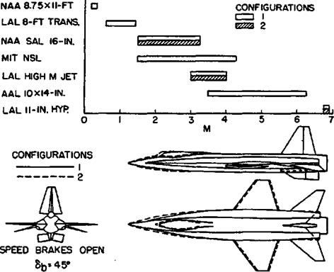
During the spring and summer of 1956, sev­eral scale models were exposed to rather intensive wind tunnel tests. A 1/50-scale – model was tested in the 11 – inch hypersonic and 9-inch blowdown tunnels at Langley, and another in a North American wind tun­nel. A 1/15-scale model was also tested at Langley and a rotary-derivative model was tested at Ames. The various wind tunnel pro­grams included investigations of the speed
brakes, horizontal stabilizers without dihe­dral, several possible locations for the hori­zontal stabilizer, modifications of the vertical stabilizer, the fuselage tunnels, and control effectiveness, particularly of the rolling-tail. Another subject in which there was consid­erable interest was determining the cross­section radii for the leading edges of the var­ious surfaces.

On 11 June 1956, North American received a production go-ahead for the three X-15 air­frames (although the first metal was not cut for the first aircraft until September). Four days later, on 15 June 1956, the Air Force assigned three serial numbers (56-6670 through 56-6672) to the X-15 program.8

By July, the NACA felt that sufficient progress had been made on the X-15 devel­opment to make an industry conference on the project worthwhile.8 The first Conference on the Progress of the X-15 Project was held

WIND-TUNNEL PROGRAM


X-15 Design and DevelopmentSeven different wind tunnels are represent­ed in this chart show­ing how the extreme front of the fuselage tunnels began to be modified. Note the large speed brakes on the vertical stabilizer.
“LAC on the chart is the Langley Aeronautical Laboratory, while “AAL” is the Ames Aeronautical Laboratory.

(NASA)

at Langley on 25-26 October 1956. There were 313 attendees representing the Air Force, the NACA, Navy, various universities and colleges, and most of the major aero­space contractors. It was evident from the papers that a considerable amount of progress had already been made, but that a few significant problems still lay ahead.10

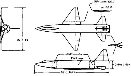
A comparison of the suggested configuration contained in the original NACA proposal and the North American configuration pre­sented to the industry conference revealed that the span of the X-15 had been reduced from 27.4 feet to only 22 feet and that the North American fuselage had grown from the suggested 47.5-foot overall-length to 49 feet. North American followed the NACA suggestion by selecting Inconel X as the major structural material and in the design of a multispar wing with extensive use of cor­rugated webs.11

One of the papers summarized the aerody­namic characteristics that had been obtained by tests in eight different wind tunnels.12 These tests had been made at Mach numbers ranging from less than 0.1 to about 6.9, and investigated such problems as the effects of speed brake deflection on drag, the lift-drag relationship of the entire aircraft, of individ­ual components such as the wings and fuse­lage tunnels, and of combinations of individ­ual components. One of the interesting prod­ucts was a finding that almost half of the total lift at high Mach numbers would be derived from the fuselage tunnels. Another
result was the confirmation of the NACA’s prediction that the original fuselage tunnels would cause longitudinal instability; for sub­sequent testing the tunnels had been short­ened in the area ahead of the wing, greatly reducing the instability. Still other wind tun­nel tests had been conducted in an effort to establish the effect of the vertical and hori­zontal tail surfaces on longitudinal, direc­tional, and lateral stability.

It should be noted that wind tunnel testing in the late 1950s was, and still is, an inexact sci­ence. For example, small (3- to 4-inch) mod­els of the X-15 were “flown” in the hyper­velocity free-flight facility at Ames. The models were made out of cast aluminum, cast bronze, or various plastics, and were actually fairly fragile. Despite this, the goal was to shoot the model out of a gun at tremendous speeds in order to observe shock wave patterns across the shape. As often as not, what researchers saw were pieces of X-15 models flying down the range side­ways, Fortunately, enough of the models remained intact to acquire meaningful data.13

Other papers presented at the industry con­ference dealt with research into the effect of the aircraft’s aerodynamic characteristics on the pilot’s control. Pilot-controlled simula­tion flights for the exit and reentry phases had been conducted; researchers reported that the pilots had found the early configura­tions nearly uncontrollable without damping, and that even with dampers the airplane pos­sessed only minimum stability during parts

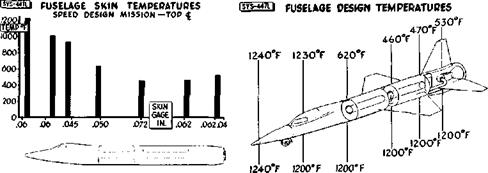
These charts show the expected tempera­tures and skin thick­ness for various parts of the Х-15’s fuselage.

X-15 Design and DevelopmentNote the large differ­ence between top-side temperatures and those on the bottom of the fuselage. (NASA)
г


of the programmed flight plan. A program utilizing a free-flying model had proved low – speed stability and control to be adequate. Since some aerodynamicists had questioned North American’s use of the rolling-tail instead of ailerons, the free-flying model had also been used to investigate that feature. The results indicated that the rolling-tail would provide the necessary lateral control.

Several papers presented at the conference dealt with aerodynamic heating. One of these was a summary of the experience gained with the Bell X-1B and X-2. The information was incomplete and not fully applicable to the X-15, but it did provide a basis for compari­son with the results of the wind tunnel and analytical studies. Another paper dealt with the results of the structural temperature esti­mates that had been arrived at analytically. It was apparent from the contents of the papers that the engineers compiling them were con­fronted by a paradox—in order to attain an adequate and reasonably safe research vehi­cle, they had to foresee and compensate for the very aerodynamic heating problems that were to be explored by the completed aircraft.

In addition to the papers on the theoretical aspects of aerodynamic heating, a report was made on the structural design that had been accomplished at the time of the conference. Critical loads would be encountered during the accelerations at launch weight and during reentry into the atmosphere, but since maxi­mum temperatures would be encountered only during the latter, the paper was largely
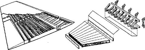
confined to the results of the investigations of the load-temperature relationships that were anticipated for the reentry phase. The selection of Inconel X skin for the multispar box-beam wing was justified on the basis of the strength and favorable creep characteris­tics of that material at 1,200 degrees Fahrenheit. A milled bar of Inconel X was to be used for the leading edge since that por­tion of the wing acted as a heat sink. The internal structure of the wing was to be of titanium-alloy sheet and extrusion construc­tion. The front and rear spars were to be flat web-channel sections with the intermediate spars and ribs of corrugated titanium webs.

For purposes of the tests the maximum tem­perature differences between the upper and lower wing surfaces had been estimated to be 400 degrees Fahrenheit and that between the skin and the center of the spar as 960 degrees Fahrenheit. Laboratory tests indicated that such differences could be tolerated without any adverse effects on the structure. Other tests had proven that thermal stresses for the Inconel-titanium structure were less than those encountered in similar structures con­structed entirely on Inconel X, Full-scale tests had been made to determine the effects of temperature on the buckling and ultimate strength of a box beam. Simply heating the test structure produced no surface buckles. Compression buckles had appeared when ultimate loads were applied at normal tem­peratures but the buckles disappeared with the removal of the load. Tests at higher tem­peratures and involving large temperature

X-15 WING


WING SUPPORTING STQUCTUQE


The wing of the X-15 was constructed from Inconel X skins over a titanium struc­ture. Unlike many air­craft, there was not a continuous spar across both wings. Instead, each wing was bolted to the fuselage. (NASA)


r


X-15 Design and Development

differences had finally led to the failure of the test box, but it seemed safe to conclude that . thermal stresses had very little effect on the ultimate strength of the box.”

Tests similar to those conducted on the wing structure had also been performed on the hor­izontal stabilizer. The planned stabilizer struc­ture differed from the wing in that it incorpo­rated a stainless steel spar about halfway between the leading and trailing edges, and an Inconel X spar three and one-half inches from the leading edge. The remainder of the inter­nal structure consisted of titanium compo­nents and the skin was Inconel X sheet. Tests of the stabilizer had indicated that a design which would prevent all skin buckling would be inordinately heavy, so engineers decided to tolerate temporary buckles. The proposed sta­bilizer had flutter characteristics that were within acceptable limits.

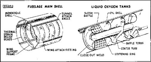
The front and rear fuselage were semimono – coque structures of titanium ribs, Inconel X outer skin, and an inner aluminum skin insu­lated with spun glass. The integral propellant tanks in the center fuselage were of full monocoque construction. The full mono – coque design used only slightly thicker skins than the semimonocoque design, possessed adequate heat sink properties, and reduced stresses caused by temperature differences by placing all of the material at the surface. It seemed, therefore, that the resulting structure was ideal for use as a pressure tank. The thickness of the monocoque walls would also make sealing easier and leaks less likely.

The fuselage side tunnels presented yet another problem. As the tunnels would pro­tect the side portions of the propellant tanks from aerodynamic heating, the sides would not expand as rapidly as the areas exposed to the air, and another undesirable compressive stress had to be anticipated. It was thought that beading the skin of the areas protected by the tunnels would provide a satisfactory solution, but beading introduced further complications by reducing the structure’s ability to carry pressure loads. Ultimately, however, the techniques proved successful.

Like most rocket engines of the period, the XLR99 would use liquid oxygen as an oxi­dizer, and a non-cryogenic fuel, in this case anhydrous ammonia.14 Each of the two main propellant tanks was to be divided into three compartments by curved bulkheads; the two compartments furthest from the aircraft cen­ter of gravity were equipped with slosh baf­fles. Plumbing was to be installed in a single compartment, the compartment sealed by a bulkhead, and the process repeated until all the compartments were completed. The tank ends were to be semicurved in shape to keep them as flat as possible, to reduce weight, and to permit thermal expansion of the tank shell. This entire structure was to be of weld­ed Inconel X.

The expected acceleration of the X-15 pre­sented several unique human factors concerns early in the program. It was expected that the pilot would be subjected to an acceleration of up to 5g. It seemed advisable to develop a

X-15 Design and Development

One of the innovations proposed by North American was the use of monocoque propel­lant tanks, leading to the use of the contro­versial fuselage tun­nels. The forward-most part of the LOX tank was equipped with slosh baffles. (NASA)

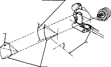
side-stick controller that would allow the pilot’s arm to be supported by an armrest while still allowing him of full control over the aircraft.15 Coupled with the fact that there were two separate attitude-control systems on the X-15, this resulted in a unique control stick arrangement. A conventional center stick, similar to that installed in most fighter – type aircraft of the era, was connected to the aerodynamic control surfaces through a sta­bility-augmentation (damper) system. A side – stick controller on the right console was con­nected to the same aerodynamic control sur­faces and augmentation system. Either stick could be used interchangeably, although the flight manual16 describes using the center stick “during normal periods of longitudinal and vertical acceleration.” The center stick was occasionally omitted from flights later in the flight research program based on pilot prefer­ences. Another side-stick controller on the left console operated the so-called “ballistic con­trol” system17 (thrusters) that provided attitude control at high altitudes. The flight manual warns that “velocity tends to sustain itself after the stick is returned to the neutral posi­tion. A subsequent stick movement opposite to the initial one is required to cancel the orig­inal attitude change.”

At the time of the industry conference in 1956, the design for the X-15 side controller had not been definitely established but a summary of the previous experience with such controllers was available. Experimental controllers had been installed on a Grumman F9F-2, Lockheed TV-2, Convair F-102, and on a simulator. The pilots who had tried side controllers had reported no difficulty in maneuvering, but they generally felt that greater efforts would have to be made to eliminate backlash and to control friction forces; they had also urged that efforts be made to give the side controllers a more “natural” feel.

Another problem which had not been thor­oughly explored at the time of the 1956 con ference concerned the proposed reaction con­trols that would be necessary for the X-15 as dynamic pressures decreased to the point where the aerodynamic controls would no longer be effective. Analog computer and ground simulator studies were then under way in an effort to determine the best relationship between the control thrust and the pilot’s movement of the control stick. Attempts were also being made to determine the amount of propellant that would be required for the reac-

ШШ CONSOLE AERODYNAMIC CONTROL


PITCH THROW WRIST RESTRAINED 6s«IO°TO-35°


The X-15 contained two side-stick con­trollers; one for the aerodynamic controls (shown), and one on the other console for the reaction controls. Although the side-stick proved very success­ful on the X-15, it would be another 20 years before one was installed on an opera­tional aircraft (the General Dynamics F-16). (NASA)


e


STICK REE POINT PITCH AND ROLL ENVELOPE OF MOTION


ti

tf


ROLL AXIS


о


NOSE DOWN LIMIT


X-15 Design and Development

tion controls. No significant problems were uncovered during these early investigations, but it was clear that the pilot would have to give almost constant attention to such a con­trol system and that pilots should be given extensive practice on simulators before being allowed to attempt actual flight.

Some of the anticipated difficulties in the field of instrumentation arose because available strain gauges were not considered satisfactory at the expected high temperatures and because of difficulties in recording the output of ther­mocouples. Large structural deformations of wings and empennage were to be recorded by cameras in special camera compartments. Another instrumentation problem arose because the sensing of static pressure, ordi­narily difficult at high Mach numbers, was compounded in the case of the X-15 by heat­ing that would be too great for any conven­tional probe and by the low pressure at the high altitudes to be explored. The answer was to develop a stable-platform-integrating- accelerometer system to provide velocity, alti­tude, pitch, yaw, and roll angle information.

Still another instrumentation difficulty was created by the desirability of presenting the
pilot with angle-of-attack and side slip infor­mation, especially for the critical exit and reentry periods. Any device to furnish this information would have to be located ahead of the aircraft’s own flow disturbances, be structurally sound at elevated temperatures, accurate at low pressures, and cause a mini­ma) flow disturbance so as not to interfere with the heat transfer studies that were to be conducted in the forward area of the fuse­lage. These requirements had resulted in the design of a ball-nose16 capable of withstand­ing 1,200 degrees Fahrenheit. A six-inch diameter Inconel X sphere located in the extreme nose of the X-15 was gimbaled19 and servo-driven in two planes. It had five open­ings: a total-head port opening directly for­ward and two pairs of angle-sensing ports in the pitch and yaw planes, located at an angle of 30 to 40 degrees from the central port. Pitch and yaw could be sensed as pressure differences and these differences were con­verted into signals that would cause the ser­vos to realign the sphere in the relative wind.

Based largely on urgings from Scott Crossfield, the Air Force agreed to allow North American to design an ejection seat and to make a study justifying the selection

X-15 Design and DevelopmentAlthough the ejection seat showed at the 1956 industry confer­ence did not resemble the final unit used in the X-15s, the basic concepts remained the same. Restraining the pilot’s head, arms, and legs during ejec­tion at high dynamic pressures presented one of the major chal-. lenges to seat devel­opment. (NASA)

of a seat in preference to a capsule system.20 Two main criteria had governed the selec­tion of an escape system for the X-15, and these criteria were not necessarily comple­mentary. The first requirement was that the system be the most suitable that could be designed while remaining compatible with the airplane. The second was that no system would be selected that would delay the development of the X-15 or leave the pilot without any method of escape when the time arrived for flight research. The four possible escape systems that were consid­ered included cockpit capsules, nose cap­sules, a canopy shielded seat, and a stable – seat with a pressure-suit. An analysis of the expected flight hazards had indicated that because of the fuel exhaustion and low aerodynamic loads, the accident potential at peak speeds and altitudes was only about two percent of the total.

Capsule-like systems had been tried before, most notably in the X-2 where the entire for­ward fuselage could be detached from the rest of the aircraft. Model tests showed these to be very unstable and prone to tumble at a high rate of rotation. They also added a great deal of weight and complexity to the aircraft,21

The final decision for a stable-seat with a pressure-suit was made because most of the potential accidents could be expected to occur at speeds of Mach 4 or less, because system reliability always decreased with sys­tem complexity, and finally, because it was the system that imposed the smallest weight and size penalties upon the aircraft. The selected system would not function success­fully at altitudes above 120,000 feet or speeds in excess of Mach 4, but designers, particu­larly Scott Crossfield, held that the aircraft itself would offer the best protection in the areas of the performance envelope where the seat-suit combination was inadequate.

Cockpit and instrument cooling, pressuriza­tion, suit ventilation, windshield defogging, and fire protection were all to be provided from a liquid nitrogen supply. Vaporization of the liquid nitrogen would keep the pilot’s environment within comfortable limits at all times. An interesting aspect of the cooling problem was an estimate that only 1.5 per­cent of the system’s capacity would be applied to the pilot; the remaining 98.5 per­cent was required for equipment. Cockpit temperatures were to be limited to no more than 150 degrees Fahrenheit, the maximum

X-15 Design and DevelopmentThis chart shows that 92 percent of the expected X-15 acci­dents would happen below Mach 2 and

90,0 feet. This esti­mate supported Scott Crossfield’s request to use an ejection seat and pressure suit instead of a more complex escape cap­sule. (NASA)

limit for some of the equipment. The pilot would not be subjected to that temperature, however, as the pressure suit ventilation would enable him to select a comfortable temperature level. Cockpit pressure was to be maintained at the 35,000 foot level.

The effects of flight accelerations upon the pilot’s physiological condition and upon his ability to avoid inadvertent control move­ments had not been completely explored, but it was recognized that high accelera­tions could pose medical and restraint diffi­culties. In addition to the accelerations that would be encountered during the exit and reentry phases of the X-15’s flights, a very high acceleration of short duration would be produced during the landings. This was a result of the location of the main skids at the rear of the aircraft. Once the skids touched down, the entire aircraft would act as if it were hinged at the skid attachment points and the nose section would slam downward. Reproduction of this landing acceleration on simulators showed that because of the short duration, no real prob­lem existed. There were, however, numer­ous complaints about the severity of the jolts both in the simulator and once actual landings began.

The final paper presented to the 1956 indus­try conference was an excellent summary of the development effort and a review of the major problems that were known at that time. The author, Lawrence R Greene from North American, considered flutter to be an unsolved problem, primarily because of a lack of basic data on aero-thermal-elastic relationships and because little experimental data was available on flutter at hypersonic Mach numbers. He pointed out that available data on high-speed flutter had been derived from experiments conducted at Mach 3 or less, and that not all of the data obtained at those speeds were applicable to the problems faced by the designers of the X-15. As it turned out, panel flutter was encountered early in the flight test program, leading to a change in the design criteria for high-speed aircraft. Another difficulty was the newness of Inconel X as a structural material and the necessity of experimenting with fabrication techniques that would permit its use as the primary structural material for the X-15. Problems were also expected to arise in con­nection with sealing materials, most of which were known to react unfavorably when subjected to high temperature condi­tions.22 Although North American did encounter initial problems in using Inconel

X-15 Design and DevelopmentDespite its perform­ance potential, the basic cockpit design of the X-15 was quite conventional, with the exception of the side – stick controllers. The engine instrumenta­tion on the lower left of the instrument panel would be differ­ent for the XLR11 flights. The addition of the MH-96 in the X-15-3 would necessi­tate some changes in the instrumentation. See page 63 for a photo. (NASA)
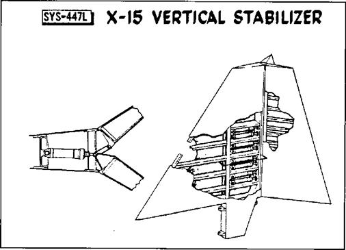
X and titanium during the construction of the X-l5, it was able to work through the diffi­culties with no major delays.

A development engineering inspection was held at the North American Inglewood plant on 12-13 December 1956. This inspection of a full-scale tnockup was intended to reveal unsatisfactory design features before fabrication of the aircraft got under way. Thirty-four of the forty-nine individuals who participated in the inspection were rep­resentatives of the Air Force; twenty-two of them from WADC. The important role of the Air Force was also evident from the composition of the committee that would review the requests for alteration.2’ Major E. C. Freeman, of ARDC, served as committee chairman, Mr. F. Orazio of WADC and Lieutenant Colonel Keith G. Lindell of Air Force Headquarters were committee mem­bers, and Captain Chester E. McCollough, Jr. of the ARDC and Captain Iven C. Kincheloe, Jr. of the Air Force Flight Test Center (AFFTC) served as advisors. The Navy and the NACA each provided a single committee member; three additional advi­sors were drawn from the NACA.

The inspection committee considered 84 requests for alterations, rejected 12, and placed 22 in a category for further study. The majority of the 50 changes that were accept­ed were minor, such as the addition of longi­tudinal trim indications from the stick posi­tion and trim switches, relocation of the bat­tery switch, removal of landing gear warning lights, rearrangement and redesign of warn­ing lights, and improved markings for sever­al instruments and controls.

Some of the most interesting comments were rejected by the committee. For instance, the suggestions that the aerodynamic and reac­tion controller motions be made similar, that the reaction controls be made operable by the same controller used for the aerodynam­ic controls, or that a third controller combin­ing the functions of the aerodynamic and reaction controllers be added to the right console, were all rejected on the grounds that actual flight experience was needed with the controllers already selected before a decision could be made on worthwhile improvements or combinations. As two of the three sugges­tions on the controllers came from potential pilots of the X-l5 (Joseph A. Walker and

X-15 Design and DevelopmentThe vertical stabilizer was one of the most obvious changes between the industry conference configura­tion and the final vehi­cle. The first design did not use the exag­gerated wedge-shape of the final unit. It was also more traditional, using a fixed forward portion and a conven­tional appearing rud­der. The final version used an all-moving design. Note the rud­der splits to become speed brakes, much like the shuttle design 25 years later. (NASA)
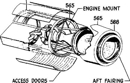
Iven C. Kincheloe, Jr.24), it would appear that the planned controllers were not all that might have been desired.

A request that the pilot be provided with continuous information on the nose-wheel door position (loss of the door could produce severe structural damage) was rejected because the committee felt that the previous­ly approved suggestion for gear-up inspec­tion panels would make such information unnecessary. This particular item would come back to haunt the program during the flight research phase.

After the completion of the development engineering inspection, the X-15 airframe design changed only in relatively minor details. North American essentially built the X-15 described at the industry conference in October and inspected in mockup in December 1956. Continued wind tunnel test­ing resulted in some external modifications, particularly of the vertical stabilizer, and some weight changes occurred as plans became more definite. But while work on the airframe progressed smoothly, with few unexpected problems, the project as a whole did encounter difficulties, some of them seri­ous enough to threaten long delays. In fact, North American’s rapid preparation of draw­ings and production planning served to high­light the lack of progress on some of the components and subsystems that were essen­tial to the success of the program.

Papers Published

Not the least of the technological legacies of the X-15 consisted of the more than 765 technical documents produced in association with the program, including some 200 papers reporting on general research that the X-15 inspired. John Becker saw them as “confirmation of the massive stimulus and the focus provided by the [X-15] program.”51

Other Views

William Dana took time in 1987 to write a paper for the Society of Experimental Test Pilots pointing out some of the lessons learned from the X-15 program.52 Dana should know—he was the last pilot to fly the X-15. Two he cited were particularly appro­priate to the designers of the X-30 and X-33, although neither heeded the lessons. They are included here in their entirety:

The first lesson from the X-15 is: Make

it robust. As you have already seen, the

X-15 was able to survive some severe mistreatment during landings and still came back to fly another day. The X-15 that broke up after a spinning re-entry had self-recovered from the spin prior to break up, and might well have survived the entire episode had fixed, rather than self-adaptive, damper gains been used during re-entry. Another example exists of where the X-15 did survive a major stress in spite of operating with a major malfunction. This flight occurred in June 1967, when Pete Knight launched in X-15 No. 1 on a planned flight to

250,0 feet. At Mach 4 and at an alti­tude of 100,000 feet during the boost, the X-15 experienced a complete electri­cal failure that resulted in shutdown of both auxiliary power units and, there­fore loss of both hydraulic systems. Pete was eventually able to restart one of the auxiliary power units, but not its gener­ator. By skillful use of the one remain­ing hydraulic system and the ballistic controls, Pete was able to ride the X-15 to its peak altitude of 170 or 180,000 feet, reenter, make a 180 degree turn back to the dry lake at Tonopah, and dead-stick the X-15 onto the lakebed. All of these activities occurred without ever flowing another electron through the airplane from the time of the original failure.

There will be a hue and cry from some that the aerospace plane [X-30—NASP] cannot afford the luxury of robustness; that the aerospace plane, in order to be able to get to orbit, will have to be highly weight-efficient and will have to forego the strength and redundancy margins which allowed the X-15 to survive during adversity. And my answer to these people is: build your first aerospace plane with X-15 margins, even at the expense of per­formance; these margins will serve well while you are learning how to make your propulsion system operate and learning how to survive in the heating thicket of hypersonic flight. Someday, with this

knowledge in hand, it will be time to build a no-margins aerospace plane, but for now I suggest that you seize all the margins that you can because you will need them, as did the X-15.

The other lesson from the X-15 is: con­duct envelope expansion incrementally. The typical increment of speed increase for the original X-15 was about half a Mach number. With this increment it was easy to handle the heating damage that occurred in the original speed expansion phase. Again, I would expect to hear protest from the aerospace plane community, because when using one – half Mach number increments it is a long flight test program to Mach 25. Indeed, I cannot specify what size bite to take during the aerospace plane enve­lope expansion, but I can offer you the X-15A experience, in which two con­secutive flights carrying the dummy ramjet were flown to Mach numbers of 4.94 and 6.70. The former flight exhibit­ed no heat damage because of the wake of the dummy ramjet; the latter flight almost resulted in the loss of the aircraft due to heat damage.

Looking at the X-33 program in particular, another lesson jumps out. There will only be a single X-33. The building of three X-15s allowed the flight test program to proceed even after accidents. In fact, each of the X-15s was severely damaged at some time or another requiring it to be rebuilt. Plus, with multiple aircraft, it is possible to have one aircraft down for modification while the oth­ers continue to fly. And should one aircraft be lost, as sometimes happens in flight research, the program can continue. In today’s environment it is highly unlikely that the X-33 program would continue if it exploded during an engine test like the X-15-3 did while ground testing the XLR99. Hopefully the X-33 will not experience such a failure, but is that not part of the reason we conduct flight research—to learn from the failures as well as the successes?

The Engine

Those concerned with the success of the X-15 had to monitor the development of the aircraft itself, the XLR99 rocket engine, the auxiliary power units, an inertial system, a tracking range, a pressure suit, and an ejection seat. They had to make arrangements for support and B-36 carrier aircraft, ground equipment, the selection of pilots, and the development of simulators for pilot training. It was necessary to secure time on centrifuges, in wind tunnels, and on sled tracks. The ball-nose had to be developed, studies made of the compatibility of the X-15 and the carrier aircraft, and other studies on the possibility of extending the X-15 program beyond the goals originally contemplated. In addition to such tasks, funds to cover ever increasing costs had to be secured if the project were to have any chance of ultimate success, and at certain stages the effects of possibly harmful publicity had to be considered. With such multiplicity of tasks, it could be expected that several serious prob­lems would arise; not surprisingly, probably the most serious arose during the develop­ment of the XLR99.

Finding a suitable engine for the X-15 had been somewhat problematic from the earliest stages of the project, when the WADC Power Plant Laboratory had pointed out that the lack of an acceptable rocket engine was the major shortcoming of the NACA’s original propos­al. The laboratory did not believe that any available engine was entirely suitable for the X-15 and held that no matter what engine was accepted, a considerable amount of development work could be anticipated. Most of the possible engines were either too small or would need too long a development peri­od. In spite of these reservations, the labora­tory listed a number of engines worth consid­ering and drew up a statement of the require­ments for an engine that would be suitable for the proposed X-15 design. The laboratory also made clear its stand that the government should “… accept responsibility for develop­ment of the selected engine and… provide this engine to the airplane contractor as Government Furnished Equipment.”2′

The primary requirement for an X-15 engine, as outlined in 1954, was that it be capable of operating safely under all condi­tions. Service life would not have to be as long as for a production engine, but engi­neers hoped that the selected engine would not depart too far from production standards. The same attitude was taken toward reliabil­ity; the engine need not be as reliable as a production article, but it should approach such reliability as nearly as possible. There could be no altitude limitations for starting

or operating the engine, and the power plant would have to be entirely safe during start, operation, and shutdown, no matter what the altitude. The laboratory made it quite clear that a variable thrust engine capable of repeated restarts was essential.

The engine ultimately selected was not one of the four originally presented as possibil­ities by the Power Plant Laboratory. The ultimate selection was foreshadowed, how­ever, in discussions with Reaction Motors concerning the XLR10, during which atten­tion was drawn to what was termed "… a larger version of [the] Viking engine [XLR30].” In light of subsequent events, it was interesting to note that the laboratory thought26 the XLR30 could be developed into a suitable X-15 engine for less than $5,000,000 …” and with “ … approximate­ly two years’ work.”27

After North American had been selected as the winner of the X-15 competition, plans were instituted to procure the modified XLR30 engine that had been incorporated in the winning design. Late in October, Reaction Motors was notified that North American had won the X-15 competition and
that the winner had based his proposals upon the XLR30 engine.28

On 1 December 1955 a $1,000,000 letter con­tract was initiated with Reaction Motors for the development of a rocket engine for the X-15.-"’ Soon afterwards, a controversy devel­oped over the assignment of cognizance for the development of the engine. It began with a letter from Rear Adm. W. A. Schoech of the Bureau of Aeronautics. Adm. Schoech con­tended that since the XLR30-RM-2 rocket engine was the basis for the X-15 power plant, and the BuAer had already devoted three years to the development of that engine, it would be logical to assign the responsibili­ty for further development to the Navy. The admiral felt that retention of the program by the BuAer would expedite development, especially as the Navy could direct the devel­opment toward an X-15 engine by making specification changes rather than by negotiat­ing a new contract.30

The Navy’s bid for control of the engine development was rejected on 3 January 1956 on the grounds that the management respon­sibility should be vested in a single agency, that conflict of interest might generate delay,

Подпись:
The EngineThe XLR99 was an extremely compact engine, considering it was able to produce over 57,000 pounds – thrust. This was the first throttleable and restartable man-rated rocket engine. Many of the lessons-learned from this engine were incorporated into the Space Shuttle Main Engine developed 20 years later. (NASA)
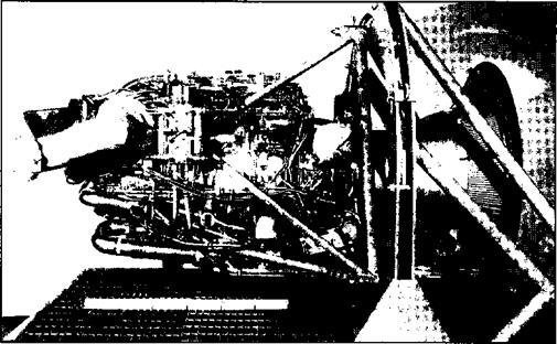
and that BuAer was underestimating the time and effort necessary to make the XLR30 a satisfactory engine for piloted flight.

The Final Reaction Motors technical propos­al was received by the Power Plant Laboratory on 24 January, with the cost pro­posal following on 8 February.31 The cover letter from Reaction Motors promised deliv­ery of the First complete system “… within thirty (30) months after we are authorized to proceed.”32 Reaction Motors also estimated that the entire cost of the program would total $10,480,718.33 On 21 February the new engine was designated XLR99-RM-1.34

The 1956 industry conference heard two papers on the proposed engine and propul­sion system for the X-15. The XLR99-RM-1 would be able to vary its thrust from 19,200 to 57,200 pounds at 40,000 feet using anhy­drous ammonia and liquid oxygen (LOX)35 as propellants. Specific impulse was to vary from a minimum of 256 seconds to a maxi­mum of 276 seconds. The engine was to Fit into a space 71.7 inches long and 43.2 inch­es in diameter, have a dry weight of 618 pounds, and a wet weight of 748 pounds. A single thrust chamber was supplied by a
hydrogen-peroxide-driven turbopump, with the turbopump’s exhaust being recovered in the thrust chamber. Thrust control was by regulation of the turbopump speed.36

The use of ammonia as a propellant present­ed some potential problems; in addition to being toxic in high concentrations, ammonia is also corrosive to all copper-based metals. There were discussions early in the program between the Air Force, Reaction Motors, and the Lewis Research Center37 about the possi­bility of switching to a hydrocarbon fuel. It was finally concluded that changing fuel would add six months to the development schedule; it would be easier to learn to live with the ammonia.38 There is no documenta­tion that the ammonia ultimately presented any significant problems to the program.

The decision to control thrust by regulating the speed of the turbopump was made because the other possibilities (regulation by measurement of the pressure in the thrust chamber or of the pressure of the discharge) would cause the turbopump to speed up as pressure dropped. As the most likely cause of pressure drop would be cavitation in the pro­pellant system, an increase in turbopump

HEM) PP0PULSI0N-SYSTEM PILOT CONTROLS


This 1956 sketch shows the controls and indicators for the XLR99. A different set of controls were used for the XLR11 flights, although they fit into the same space allo­cation. Notice the sim­ple throttle on the left console, underneath the reaction control side-stick (not shown).

The jettison controls took on particular sig­nificance on missions that had to be aborted prior to engine burn­out. (NASA)


INSTRUMENT PANEL-


ENGINE INDICATOR LIGHTS


TANK PRESSURE t JETTISON CONTROLS


ENGINE CONTROL SWITCHES


-CHAMBER

PRESSURE

-TOTAL

IMPULSE

REMAINING


STOP JETT.


PROPELLANT-SYSTEM t PURGE-SYSTEM PRESSURES


-THROTTLE


The Engine

speed would aggravate rather than correct the situation. Reaction Motors had also decided that varying the injection area was too complicated a method for attaining a variable thrust engine and had chosen to vary the injection pressure instead.

The regenerative cooling of the thrust cham­ber created another problem since the vari­able fuel flow of a throttleable engine meant that the system’s cooling capacity would also vary and that adequate cooling throughout the engine’s operating range would produce excessive cooling under some conditions. Engine compartment temperatures also had to be given more consideration than in previ­ous rocket engine designs because of the higher radiant heat transfer from the struc­ture of the X-15. Reaction Motors’ spokesman at the 1956 industry conference concluded that the development of the XLR99 was going to be a difficult task. Subsequent events were certainly to prove the validity of that prediction.

A second paper dealt with engine and acces­sory installation, the location of the propel­lant system components, and the engine con­trols and instruments. The main propellant tanks were to contain the LOX, ammonia, and the hydrogen peroxide. The LOX tank,
with a capacity of approximately 1,000 gal­lons, was located just ahead of the aircraft’s center of gravity; the 1,400 gallon ammonia tank was just aft of the same point. A center core tube within the LOX tank would pro­vide a location for a supply of helium under a pressure of 3,600 psi. Helium was used to pressurize both the LOX and ammonia tanks. A 75-gallon hydrogen peroxide tank behind the ammonia tank provided the monopropel­lant for the turbopump.

Provision was also made to top-off the LOX tank from a supply carried aboard the carrier aircraft; this was considered to be beneficial in two ways. The LOX supply in the carrier aircraft could be kept cooler than the oxygen already aboard the X-15, and the added LOX would permit cooling of the X-15’s own sup­ply by boil-off, without reduction of the quantity available for flight. The ammonia tank was not to be provided with a top-off arrangement, as the slight increase in fuel temperature during flight was not considered significant enough to justify the complica­tions such a system would have entailed.

On 10 July 1957, Reaction Motors advised the Air Force that an engine satisfying the contract specifications could not be devel­oped unless the government agreed to a nine-

The Engine

The XLR99 on a main­tenance stand. The engine used ammonia (NH3) as fuel and liq­uid oxygen (LOX) as the oxidizer. The XLR99 required a sep­arate propellant, hydro­gen peroxide, to drive its high-speed turbop­ump—the Space Shuttle Main Engine uses the propellant itself (LH2 or L02, as appropriate) to drive the turbopumps. (AFFTC via the Tony Landis Collection)

month schedule extension and a cost increase from $15,000,000 to $21,800,000. At the same time, Reaction Motors indicated that it could provide an engine that met the per­formance specification within the established schedule if permitted to increase the weight from 618 pounds to 836 pounds. The compa­ny estimated that this overweight engine could be provided for $17,100,000. The Air Force elected to pursue the heavier engine since it would be available sooner and have less impact on the overall X-l5 program.

Those who hoped that the overall perform­ance of the X-l5 would be maintained were encouraged by a report that the turbopump was more efficient than anticipated and would allow a 197 pound reduction in the amount of hydrogen peroxide necessary for its operation. This decrease, a lighter than expected airframe, and the increase in launch speeds and altitudes provided by a recent substitution of a B-52 as the carrier aircraft, offered some hope that the original X-l5 per­formance goals might still be achieved.39

Despite the relaxation of the weight require­ments, the engine program failed to proceed at a satisfactory pace. On 11 December 1957 Reaction Motors reported a new six-month slip. The threat to the entire X-l5 program posed by these new delays was a matter of serious concern, and on 7 January 1958, Reaction Motors was asked to furnish a detailed schedule and to propose means for solving the difficulties. The new schedule, which reached WADC in mid-January, indi­cated that the program would be delayed another five and one-half months and that costs would rise to $34,400,000—double the cost estimate of the previous July.10

In reaction, the Air Force recommended increasing the resources available to Reaction Motors and proposed the use of two 11 XLR11 rocket engines as an interim installation for the initial X-l5 flights. Additional funds to cover the increased effort were also approved, as was the estab­lishment of an advisory group.42

The threat that engine delays would serious­ly impair the value of the X-l5 program had generated a whole series of actions during the first half of 1958: personal visits by gen­eral officers to Reaction Motors, numerous conferences between the contractor and representatives of government agencies, increased support from the Propulsion Laboratory43 and the NACA, an increase in funds, and letters containing severe censure of the company’s conduct of the program. An emergency situation had been encountered, emergency remedies were used, and by mid­summer improvements began to be noted.

Engine progress continued to be reasonably satisfactory during the remainder of 1958. A destructive failure that occurred on 24 October was traced to components that had already been recognized as inadequate and were in the process of being redesigned. The failure, therefore, was not considered of major importance.41 A long-sought goal was finally reached on 18 April 1959 with completion of the Preliminary Flight Rating Test (PFRT). The flight rating program began at once.13

At the end of April, a “realistic” schedule for the remainder of the program showed that the Flight Rating Test would be completed by 1 September 1959. The first ground test engine was delivered to Edwards AFB at the end of May, and the first flight engine was delivered at the end of July.4*

A total of 10 flight engines were initially procured, along with six spare injector – chamber assemblies; one additional flight engine was subsequently procured. In January 1961, shortly after the first XLR99 test flight, only eight of these engines were available to the flight test program. There was still a number of problems with the engines that Reaction Motors was continuing to work on; the most serious being a vibra­tion at certain power levels, and a shorter than expected chamber life. There were four engines being used for continued ground tests, including two flight engines.47 Three of the engines were involved in tests to isolate

and eliminate the vibrations, while the fourth engine was being used to investigate extend­ing the life of the chamber.48

It is interesting to note that early in the pro­posal stage, North American determined that aerodynamic drag was not as important a design factor as was normally the case with jet-powered fighters. This was largely due to the amount of excess thrust available from the XLR99. Weight was considered a larger driver in the overall airplane design. Only about 10 percent of the total engine thrust was necessary to overcome drag, and anoth­er 20 percent to overcome weight. The remaining 70 percent of engine thrust was available to accelerate the X-l5.44

The New Millennium

As we enter the new millennium, it is inter­esting to note how the X-15 has shaped aero­nautics and astronautics. Indeed, when the X-33 program began during 1996, it was sur­prising to find that many of the younger con­tractor engineers were totally unaware of the X-15, and that most thought the SR-71 was the fastest aircraft that had ever flown, dis­counting the Space Shuttle. Interestingly, the young engineers at Dryden remembered the program, and when it came to setting up the instrumentation range (which extends all the way to the Dakotas), lessons learned from the X-15 High Range were used.53

The most obvious difference today has absolutely nothing to do with the technology of hypersonic flight. It is the political climate that surrounds any large project. The NASA Administrator, Daniel Goldin, told an X-33 all-hands meeting that it was “okay to fail”—a reference that many times in order to succeed, you first have to experience prob­lems that appear to be failures. But this is not the climate that actually exists. Any failure is often used as an excuse to cut back or cancel a project. In most cases the only way to total­ly avoid failure is to completely understand what you are doing; but if you completely understood something, there would be no point in building an X-plane!

The X-15 is usually regarded as the most suc­cessful flight research program ever undertak­en. But the program had its share of failures. The XLR99 destroyed the X-15-3 before it had even flown; but the aircraft was rebuilt and the XLR99 became a very successful research engine. On several occasions the X-15s made hard landings, sometimes hard enough to sig­nificantly damage the aircraft; each time they were rebuilt and flew again. Mike Adams was killed in a tragic accident; but less than four months later William Dana flew the next research flight. Yes, the X-15 failed often; but its successes were vastly greater.

Perhaps we have not learned well enough.

Other Systems

In early 1958, at the very height of the furor over the problems with the XLR99, a note of warning sounded for the General Electric auxiliary power unit (APU). On 26 March 1958 and again on 11 April 1958, General Electric notified North American of its inability to meet the original specifications in the time available, and requested approval
of new specifications. North American, with the concurrence of the Air Force, agreed to modify the requirements. The major changes involved an increase in weight from 40 to 48 pounds, an increase in start time from five to seven seconds, and a revision of the specific fuel consumption curves.50

By the end of the summer 1958, the APU seemed to have reached a more satisfactory state of development, and production units were ready for shipment.51 The early captive flights beginning in 1959 would reveal some additional problems, but investigation showed that the in-flight failures had occurred partial­ly because captive testing subjected the units to an abnormal operational sequence that would not be encountered during glide and powered flight. Some components were redesigned, but the APU would continue to be relatively troublesome in actual service.

During the course of the X-l 5 program, many concerns were voiced over the development of a pressure suit and an escape system. Although full-pressure suits had been studied during World War II, attempts to fabricate a practical garment had met with failure. The

Other Systems

Soule to Storms: “You have a little airplane and a big engine with a large thrust margin."

And indeed they did. The XLR99 provided

57.0 pounds-thrust to propel an aircraft that only weighed

30.0 pounds. Consider that the con­temporary F-104 Starfighter, considered something of a hot rod, weighed 20,000 pounds and its J79 only produced 15,000 pounds-thrust in full afterburner. (NASA)


THRUST USED TO ACCELERATE


DRAG PLUS WEIGHT COMPONENT


BURN-OUTH


TIME

SEC


20 30 40 50 60


80 90


Other Systems

Air Force took renewed interest in pressure suits in 1954 when it had become obvious that the increasing performance of aircraft was going to necessitate such a garment. The first result of the renewed interest was the creation of a suit that was heavy, bulky, and unwieldy; the garment had only limited mobility and various joints created painful pressure points. However, in 1955 the David Clark Company succeeded in producing a garment using a distorted-angle fabric that held some promise of ultimate success.51

Despite the early state-of-development of full-pressure suits, Scott Crossfield was con­vinced they were the way to go for X-l5. North American’s detail specifications of 2 March 1956 called for just such a garment— to be furnished by North American through a subcontract with the David Clark Company.55 A positive step toward Air Force acceptance of the idea occurred during a conference held at the North American plant on 20-22 June 1956. A full-pressure suit developed by the Navy was demonstrated during an inspection of the preliminary cockpit mockup, and although the suit still had a number of defi­ciencies, it was concluded that “… the state – of-the-art on full pressure suits should permit the development of such a suit satisfactory for use in the X-15.”54

After an extremely difficult and prolonged development process, Scott Crossfield received the first new MC-2 full-pressure suit on 17 December 1958 and, two days later, the suit successfully passed nitrogen contamina­tion tests at the Air Force Aero Medical Laboratory. The X-15 project officer attrib­uted much of the credit for the successful and timely qualification of the full-pressure suit to the intensive efforts of Crossfield.55

Fortunately, development did not stop there. On 27 July 1959, the Aero Medical Laboratory brought the first of the new A/P22S-2 pressure suits to Edwards. The consensus amongst the pilots was that it rep­resented a large improvement over the earli­er MC-2. It was more comfortable and pro­vided greater mobility; and it took only 5 minutes to put on, compared to 30 minutes for the MC-2. However, it would take anoth­er year before fully-qualified versions of the suit were delivered to the X-15 program.56

While not directly related to the pressure suit difficulties, the type of escape system to be used in the X-15 had been the subject of debate at an early stage of the program; the decision to use the stable-seat, full-pressure – suit combination had been a compromise based largely on the fact that the ejection seat was lighter and offered fewer complications than the other alternatives.

As early as 8 February 1955, the Aero Medical Laboratory had recommended a cap­sular escape system, but the laboratory had also admitted that such a system would prob­ably require extensive development. The sec­ond choice was a stable seat that incorporated limb retention features and one that would produce a minimum of deceleration.51 During meetings held in October and November 1955, it was agreed that North American would design an ejection seat for the X-15 and would also prepare a report justifying the use of such a system in preference to a capsule. North American was to incorporate head and limb restraints in the proposed seat.58

Despite the report, the Air Force was not completely convinced. At a meeting held at Wright Field on 2-3 May 1956, the Air Force again pointed out the limitations of ejection seats. In the opinion of one NACA engineer who attended the meeting, the Air Force was still strongly in favor of a capsule—partly because of the additional safety a capsule system would offer, and partly because the use of such a system in the X-15 would pro­vide an opportunity for further developmen­tal research. Primarily due to the efforts of Scott Crossfield, the participants finally agreed that because of the “time factor, weight, ignorance about proper capsule design, and the safety features being built into the airplane structure itself, the X-15 was probably its own best capsule.” About

the only result of the reluctance of the Air Force to endorse an ejection seat was a request that North American yet again docu­ment the arguments for the seat.59

The death of Captain Milbum G. Apt in the crash of the Bell X-2, which had been equipped with an escape capsule, in September 1956 renewed apprehension as to the adequacy of the X-15’s escape system.® By this time, however, it was acknowledged that no substantive changes could be made to the X-15 design. Fortunately, North American’s seat development efforts were generally proceeding well.’’1

Sled tests of the ejection seat began early in 1958 at Edwards with the preliminary tests concluded on 22 April. Because of the high cost of sled runs, the X-15 project office advised North American to eliminate the planned incremental testing and to conduct the tests at just two pressure levels—125 pounds per square foot and 1,500 pounds per square foot. The X-15 office felt that suc­cessful tests at these two levels would fur­nish adequate proof of seat reliability at intermediate pressures.62

Between 4 June 1958 and 3 March 1959, the X-15 seat completed its series of sled tests. Various problems, with both the seat and the sled, had been encountered, but all had been worked through to the satisfaction of North American and the Air Force. The X-15 seat was cleared for flight use.62

Another item for which the Air Force retained direct responsibility was the all-attitude iner­tial flight data system. It was realized from the beginning of the X-15 program that the air­plane’s performance would necessitate a new means of determining altitude, speed, and air­craft attitude. This was because the traditional use of static pressure as a reference would be largely impossible at the speeds and altitudes the X-15 would achieve; moreover, the tem­peratures encountered would rule out the use of tradition pitot tube sensing devices. The NACA had proposed a “stable-platform iner­tial-integrating and attitude sensing unit” as the means of meeting these needs.64 A series of miscommunications resulted in the NACA assuming the Air Force had already developed a satisfactory unit and would provide it to the X-15 program.65 After it was discovered that a suitable unit did not exist, emergency efforts were undertaken to develop one without impacting the X-15 program. After a consid­erable amount of controversy, a sole-source contract was awarded to the Sperry Gyroscope Company on 5 June 1957 for the development and manufacture of the stable – platform.66 The cost-plus-fixed-fee contract, signed on 5 June 1957, was for $1,213,518.06 with a fixed fee of $85,000.67

In April 1958, the Air Force concluded that the scheduled delivery of the initial Sperry unit in December would not permit adequate testing to be performed prior to the first flights of the X-15. Consequently a less capa­ble interim gyroscopic system was installed in the first two aircraft and the final Sperry system was installed in the last X-15.68

By the end of 1958, the two major system components (the stabilizer and the computer) were completed and ready to be tested as a complete unit. The systems were shipped to Edwards in late January 1959, and during the spring of 1959 plans were made to use the NB-52 carrier aircraft as a test vehicle.69 In addition, arrangements were made to test the stable-platform in a KC-97 that was already in use as a test aircraft in connection with the B-58 program.™ The first test flights in the KC-97 were carried out in late April.71 By June, North American had successfully installed the Sperry system in the third X-15 22 In January 1961, wiring was installed in the NB-52B to allow the stable-platform to be installed in a pod carried on the pylon under the wing. The first complete stable – platform system installed in the B-52 pod was flown on 1 March 1961, Since the B-52 was capable of greater speeds and higher altitudes than the KC-97, it provided addi­tional data to assist Sperry in resolving prob­lems being encountered with the unit.7’

Resolution Adopted by NACA Committee on Aerodynamics, 5 October 1954 —

Подпись: This resolution was the official beginnings of the X-15 research airplane program.RESOLUTION ADOPTED HI NACA
COMMITTEE ON AERODYNAMICS, 5 OCTOBER 1954

WHEREAS, The necessity of maintaining supremacy In the «dr continues to place great urgency on solving the problems of flight with man-carrying aircraft at greater speeds and extreme altitudes, and

WHEREAS, Propulsion systems are now capable of propelling such aircraft to speeds and altitudes that impose entirely new and unexplored aircraft design problems, and

WHEREAS, It now appears feasible to construct a research airplane capable of initial exploration of these problems,

3E IT HEREBY RESOLVED, That the Committee on Aerodynamics endorses the proposal of the 1mediate initiation of a project to design and construct a research airplane capable of achieving speeds of the order of Mach Number 7 and altitudes of several hundred thousard feet for the exploration of the problems of stability and control of manned aircraft end aerodynamic heating in the severe form asaociated with flight at extreme speeds and altitudes.

The High Range

Previous rocket aircraft, such as the X-l and X-2, had been able to conduct the majority of their flight research in the skies directly over the Edwards test areas. The capabilities of the X-l5, however, would use vastly more air­space. The proposed trajectories required an essentially straight flight corridor equipped with multiple tracking, telemetry, and com­munications sites, as well as the need for suit­able emergency landing areas. This led to con­struction of the X-l5 High Range extending from Wendover, Utah, to Edwards AFB. Radar and telemetry stations were installed at Ely and Beatty, Nevada, as well as Edwards. Telemetry from the X-l 5, as well as voice communications, were received, recorded, and forwarded to Edwards by the stations at Ely and Beatty. Each of these stations was also manned by a person to back up the prime “communicator” (NASA 1) at Edwards in
case the communication links went down. Each ground station overlapped the next, and they were interconnected via microwave and land-line so that timing signals, voice com­munication, and radar data would be available to all. Provisions were made for recording the acquired data on tape and film, although some of the data was directly displayed on strip and plotting charts. The design and construction of the range was accomplished by Electronic Engineering Company of Los Angeles under contract with the Air Force.74 North American and the NACA also conducted numerous evaluations of various dry lakes to determine which were suitable for emergency landings along the route (see the summary included as an appendix to this monograph).

Carrier Aircraft

The group at Langley had sized their X-l5 proposal around the potential of using a

The use of a B-36 car­rier aircraft would have allowed the pilot to exit the aircraft while in transit to the drop area, or in case of emergency. However, personnel at the FRC worried that the B-36 would not be supportable since it was being phased out of active service. In the end, the B-52 pro­vided much better per­formance and was ultimately selected.

The High Range(AFFTC History Office)

f


Convair B-36 as the carrier aircraft. This was a natural extension of previous X-planes that had used a Boeing B-29 or B-50 as a carrier. The B-36 would be modified to carry the X-15 partially enclosed in its bomb bays, much like the X-l and X-2 had been in earlier projects. This arrangement had some advantages; the pilot could freely move between the X-15 and B-36 during climb-out and the cruise to the launch location. This was extremely advanta­geous if problems developed that required jet­tisoning the X-15 prior to launch. At the time of the first industry conference in 1956, it was expected that a B-36 would be modified begin­ning in the middle of 1957 and be ready for flight tests in October 1958.75

As the weight of the X-15 and its subsystems grew, however, the Air Force and NASA began to look for ways to recover some of the lost performance. One way was to launch the X-15 at a higher altitude and greater speed. In addition, the personnel at Edwards believed that the ten-engine B-36 would be difficult to maintain7" since it was being phased out of the Air Force inventory. Investigations showed that the X-15, as designed, would fit under the wing of one of the new Boeing B-52 Stratofortresses; the configuration of the B-52 . precluded carrying the X-15 in the bomb bay. This was not the ideal solution—the X-15 pilot would have to be locked in the research airplane prior to takeoff, and the large weight transition when the X-15 was released would provide some interesting control problems for the B-52. Further analysis concluded that the potential problems were solvable, and that the increase in speed and altitude capabilities were desirable. Fortunately, two early B-52s were completing their test duties, and the Air Force made them available to the program.

On 29 November 1957, the B-52A (52-003) arrived at Air Force Plant 42 in Palmdale, California, after a flight from the Boeing plant in Seattle. The aircraft was placed in storage pending modifications. On 4 February 1958, the B-52A was moved into the North American hanger at Plant 42 and modified with a large pylon under the wing, the capa­
bility to monitor to the X-15, and a system to replenish the X-15 LOX supply. The aircraft, now designated77 NB-52A, was flown to Edwards AFB on 14 November 1958; it was later named “The High and the Mighty One.” The Air Force also supplied a B-52B (52-008) that arrived in Palmdale for similar modifica­tions on 5 January 1959, and was flown, as an NB-52B, to Edwards on 8 June 1959.

Roll Out

As the first X-15 was being completed, the NACA held the second X-15 industry con­ference in Los Angeles on 28-29 July 1958. North American began the conference with a paper detailing the developmental status of the aircraft. Twenty-seven other papers cov­ered subjects such as stability and control, simulator testing, pilot considerations, mis­sion instrumentation, thermodynamics, structures, materials and fabrication. There were approximately 550 attendees,78

On 1 October 1958, High-Speed Flight Station employees Doll Matay and John Hedgepeth put up a ladder in front of the sta­tion building at the foot of Lilly Avenue and took down the winged-shield NACA emblem from over the entrance door. NASA had arrived in the desert, bringing with it a new era of space-consciousness, soaring budgets, and publicity. The old NACA days of concentra­tion on aeronautics, and especially aerody­namics, were gone forever, as was the agency itself. On this day, the National Aeronautics and Space Administration was created.79

The X-15 construction process eventually consumed just over two years, and on 15 October 1958, the first aircraft (56-6670) was rolled out. Following conclusion of the official ceremonies, it was moved back inside and prepared for shipment to Edwards. On the night of 16 October, cov­ered completely in protective heavy-duty wrapping paper, it was shipped by truck to Edwards for initial ground test work.