X-15 Design and Development
Harrison A. “Stormy” Storms, Jr. led the North American X-15 design team, along with project engineer Charles H. Feltz. These two had a difficult job ahead of them, for although giving the appearance of having a rather simple configuration, the X-15 was perhaps the most technologically complex single-seat aircraft of its day. Directly assisting Storms and Feltz was test pilot A. Scott Crossfield, who had worked for the NACA prior to joining North American with the intended purpose of working on the X-15 program. Crossfield describes Storms as a man of wonderful imagination, technical depth, and courage… with a love affair with the X-15. He was a tremendous ally and kept the objectivity of the program intact….” According to Crossfield, Feltz was a remarkable ‘can do and did’ engineer who was very much a source of the X-15 success story.”1
Storms himself remembers his first verbal instructions from Hartley Sould: “You have a little airplane and a big engine with a large thrust margin. We want to go to 250,000 feet altitude and Mach 6. We want to study aerodynamic heating. We do not want to worry about aerodynamic stability and control, or the airplane breaking up. So if you make any errors, make them on the strong side. You should have enough thrust to do the job.” Adds Storms, “and so we did.”2
Crossfield’s X-15 input proved particularly noteworthy during the early days of the development program as his experience permitted the generation of logical arguments that led to major improvements to the X-15. He played a key role, for instance, in convincing the Air Force that an encapsulated ejection system was both impractical and
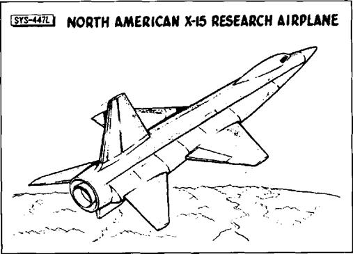 By the time of the first industry conference in 1956, this was the design baseline for the North American X-15. Note the tall vertical stabilizer, and the fact that it does not have the distinctive wedge shape of the final unit. Also notice how far forward the fuselage tunnels extend—well past the canopy. (NASA)
unnecessary. His arguments in favor of an ejection seat, capable of permitting safe emergency egress at speeds between 80 mph and Mach 4 and altitudes from sea level to 120,000 feet, saved significant money, weight, and development time.
There has been considerable interest over whether Crossfield made the right decision in leaving the NACA since it effectively locked him out of the high-speed, high-altitude portion of the X-15 flight program. Crossfield has no regrets: “… I made the right decision to go to North American. I am an engineer, aerodynamicist, and designer by training… While I would very much have liked to participate in the flight research program, I am pretty well convinced that f was needed to supply a lot of the impetus that allowed the program to succeed in timeliness, in resources, and in technical return…. I was on the program for nine years from conception to closing the circle in flight test. Every step: concept, criteria, requirements, performance specifications, detailed specifications, manufacturing, quality control, and flight operations had all become an [obsession] to fight for, protect, and share—almost with a passion.”3
Although the first, and perhaps the most influential pilot to contribute to the X-15 program, Crossfield was not the only one to do so. In fact, all of the initially assigned X-15 pilots participated in the development phases, being called on to evaluate various operational systems and approaches, as well as such factors as cockpit layout, control systems, and guidance schemes. They worked jointly with engineers in conducting the simulator programs designed to study the aspects of planned flight missions believed to present potential difficulties. A fixed – base simulator was developed at North American’s Los Angeles facility, containing a working X-15 cockpit and control system that included actual hydraulic and control – system hardware. Following use at North American, it was subsequently relocated to the Flight Research Center4 (FRC) at Edwards AFB. Once flight research began, the simulator was constantly refined with the results of the flight test program, and late in its life the original analog computers were replaced by much faster digital units. For the life of the program, every X-15 flight was preceded by 10-20 hours in the simulator.
A ground simulation of the dynamic envi-
|
![]()
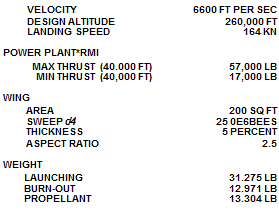
 One of the more controversial features of the North American design was the fuselage tunnels that carried the propellant lines and engine controls around the full monocoque propellant tanks, shown in this 1956 sketch. Originally these tunnels extended forward ahead of the cockpit, and the NACA worried they would create unacceptable vortices. (NASA)
ronment was provided by use of the Navy centrifuge at the Naval Air Development Center (NADC) Johnsville, Pennsylvania. Over 400 simulated reentries5 were flown during an initial round of tests completed on 12 July 1958; Iven Kincheloe, Joe Walker, Scott Crossfield, A1 White, Robert White, Neil Armstrong, and Jack McKay participated. The primary objective of the program was to assess the pilot’s ability to make emergency reentries under high dynamic conditions following a failure of the stability augmentation system. The results were generally encouraging.6
When the contracts with North American had been signed, the X-15 was some three years away from actual flight test. Although most of the basic research into materials and structural science had been completed, a great deal of work remained to be accomplished. This included the development of fabrication and assembly techniques for Inconel X and the new hot-structure design. North American met the challenge of each problem with a practical solution, and eventually some 2,000,000 engineering manhours and 4,000 wind tunnel hours in 13 different wind tunnels were logged.
The original North American proposal gave rise to several questions which prompted a meeting at Wright-Patterson AFB on 24-25 October 1955. Subsequent meetings were held at the North American Inglewood plant on 28-29 October and 14-15 November. Major discussion items included North American’s use of fuselage tunnels and allmoving horizontal stabilizers (the “rolling – tail”). The rolling-tail operated differentially to provide roll control, and symmetrically to provide pitch control; this allowed the elimination of conventional ailerons. North American had gained considerable experience with all-moving control surfaces on the YF-107A fighter. In this instance the use of differentially operated surfaces simplified the construction of the wing, and allowed elimination of protuberances that would have been necessary if aileron actuators had been incorporated in the thin wing. Such protuberances would have disturbed the airflow and created another heating problem.
One other significant difference between the configuration of the NACA design and that of the actual X-15 stemmed from North American’s use of full-monocoque propellant tanks in the center fuselage and the use
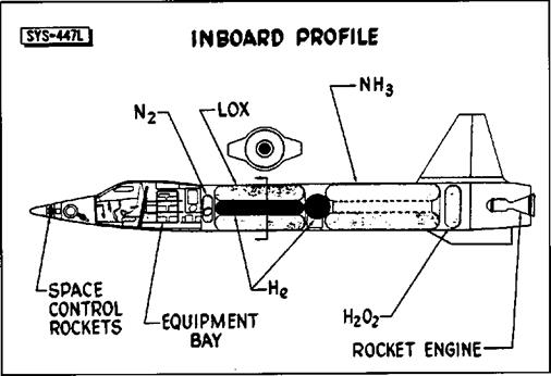
The interior layout of the fuselage did not change much after the 1956 conference. Note the helium tank located in the middle of the LOX tank. The hydrogen-peroxide (H202) was used to power the turbopump on the XLR99 rocket engine.
 (NASA)
of tunnels on both sides of the fuselage to accommodate the propellant lines and engine controls that ordinarily would have been contained within the fuselage. The NACA expressed concern that the tunnels might create undesirable vortices that would interfere with the vertical stabilizer, and suggested that the tunnels be kept as short as possible in the area ahead of the wing. North American agreed to make the investigation of the tunnels’ effects a subject of an early wind tunnel-model testing program.7
During the spring and summer of 1956, several scale models were exposed to rather intensive wind tunnel tests. A 1/50-scale – model was tested in the 11 – inch hypersonic and 9-inch blowdown tunnels at Langley, and another in a North American wind tunnel. A 1/15-scale model was also tested at Langley and a rotary-derivative model was tested at Ames. The various wind tunnel programs included investigations of the speed
brakes, horizontal stabilizers without dihedral, several possible locations for the horizontal stabilizer, modifications of the vertical stabilizer, the fuselage tunnels, and control effectiveness, particularly of the rolling-tail. Another subject in which there was considerable interest was determining the crosssection radii for the leading edges of the various surfaces.
On 11 June 1956, North American received a production go-ahead for the three X-15 airframes (although the first metal was not cut for the first aircraft until September). Four days later, on 15 June 1956, the Air Force assigned three serial numbers (56-6670 through 56-6672) to the X-15 program.8
By July, the NACA felt that sufficient progress had been made on the X-15 development to make an industry conference on the project worthwhile.8 The first Conference on the Progress of the X-15 Project was held
|
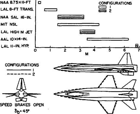 Seven different wind tunnels are represented in this chart showing how the extreme front of the fuselage tunnels began to be modified. Note the large speed brakes on the vertical stabilizer.
“LAC on the chart is the Langley Aeronautical Laboratory, while “AAL” is the Ames Aeronautical Laboratory.
(NASA)
at Langley on 25-26 October 1956. There were 313 attendees representing the Air Force, the NACA, Navy, various universities and colleges, and most of the major aerospace contractors. It was evident from the papers that a considerable amount of progress had already been made, but that a few significant problems still lay ahead.10
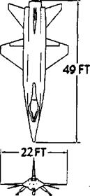
A comparison of the suggested configuration contained in the original NACA proposal and the North American configuration presented to the industry conference revealed that the span of the X-15 had been reduced from 27.4 feet to only 22 feet and that the North American fuselage had grown from the suggested 47.5-foot overall-length to 49 feet. North American followed the NACA suggestion by selecting Inconel X as the major structural material and in the design of a multispar wing with extensive use of corrugated webs.11
One of the papers summarized the aerodynamic characteristics that had been obtained by tests in eight different wind tunnels.12 These tests had been made at Mach numbers ranging from less than 0.1 to about 6.9, and investigated such problems as the effects of speed brake deflection on drag, the lift-drag relationship of the entire aircraft, of individual components such as the wings and fuselage tunnels, and of combinations of individual components. One of the interesting products was a finding that almost half of the total lift at high Mach numbers would be derived from the fuselage tunnels. Another
result was the confirmation of the NACA’s prediction that the original fuselage tunnels would cause longitudinal instability; for subsequent testing the tunnels had been shortened in the area ahead of the wing, greatly reducing the instability. Still other wind tunnel tests had been conducted in an effort to establish the effect of the vertical and horizontal tail surfaces on longitudinal, directional, and lateral stability.
It should be noted that wind tunnel testing in the late 1950s was, and still is, an inexact science. For example, small (3- to 4-inch) models of the X-15 were “flown” in the hypervelocity free-flight facility at Ames. The models were made out of cast aluminum, cast bronze, or various plastics, and were actually fairly fragile. Despite this, the goal was to shoot the model out of a gun at tremendous speeds in order to observe shock wave patterns across the shape. As often as not, what researchers saw were pieces of X-15 models flying down the range sideways, Fortunately, enough of the models remained intact to acquire meaningful data.13
Other papers presented at the industry conference dealt with research into the effect of the aircraft’s aerodynamic characteristics on the pilot’s control. Pilot-controlled simulation flights for the exit and reentry phases had been conducted; researchers reported that the pilots had found the early configurations nearly uncontrollable without damping, and that even with dampers the airplane possessed only minimum stability during parts
These charts show the expected temperatures and skin thickness for various parts of the Х-15’s fuselage.
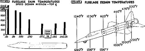 Note the large difference between top-side temperatures and those on the bottom of the fuselage. (NASA)
|
of the programmed flight plan. A program utilizing a free-flying model had proved low – speed stability and control to be adequate. Since some aerodynamicists had questioned North American’s use of the rolling-tail instead of ailerons, the free-flying model had also been used to investigate that feature. The results indicated that the rolling-tail would provide the necessary lateral control.
Several papers presented at the conference dealt with aerodynamic heating. One of these was a summary of the experience gained with the Bell X-1B and X-2. The information was incomplete and not fully applicable to the X-15, but it did provide a basis for comparison with the results of the wind tunnel and analytical studies. Another paper dealt with the results of the structural temperature estimates that had been arrived at analytically. It was apparent from the contents of the papers that the engineers compiling them were confronted by a paradox—in order to attain an adequate and reasonably safe research vehicle, they had to foresee and compensate for the very aerodynamic heating problems that were to be explored by the completed aircraft.
In addition to the papers on the theoretical aspects of aerodynamic heating, a report was made on the structural design that had been accomplished at the time of the conference. Critical loads would be encountered during the accelerations at launch weight and during reentry into the atmosphere, but since maximum temperatures would be encountered only during the latter, the paper was largely
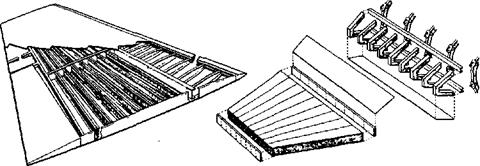
confined to the results of the investigations of the load-temperature relationships that were anticipated for the reentry phase. The selection of Inconel X skin for the multispar box-beam wing was justified on the basis of the strength and favorable creep characteristics of that material at 1,200 degrees Fahrenheit. A milled bar of Inconel X was to be used for the leading edge since that portion of the wing acted as a heat sink. The internal structure of the wing was to be of titanium-alloy sheet and extrusion construction. The front and rear spars were to be flat web-channel sections with the intermediate spars and ribs of corrugated titanium webs.
For purposes of the tests the maximum temperature differences between the upper and lower wing surfaces had been estimated to be 400 degrees Fahrenheit and that between the skin and the center of the spar as 960 degrees Fahrenheit. Laboratory tests indicated that such differences could be tolerated without any adverse effects on the structure. Other tests had proven that thermal stresses for the Inconel-titanium structure were less than those encountered in similar structures constructed entirely on Inconel X, Full-scale tests had been made to determine the effects of temperature on the buckling and ultimate strength of a box beam. Simply heating the test structure produced no surface buckles. Compression buckles had appeared when ultimate loads were applied at normal temperatures but the buckles disappeared with the removal of the load. Tests at higher temperatures and involving large temperature
|
|
|
|
|
|
|
|
differences had finally led to the failure of the test box, but it seemed safe to conclude that . thermal stresses had very little effect on the ultimate strength of the box.”
Tests similar to those conducted on the wing structure had also been performed on the horizontal stabilizer. The planned stabilizer structure differed from the wing in that it incorporated a stainless steel spar about halfway between the leading and trailing edges, and an Inconel X spar three and one-half inches from the leading edge. The remainder of the internal structure consisted of titanium components and the skin was Inconel X sheet. Tests of the stabilizer had indicated that a design which would prevent all skin buckling would be inordinately heavy, so engineers decided to tolerate temporary buckles. The proposed stabilizer had flutter characteristics that were within acceptable limits.
The front and rear fuselage were semimono – coque structures of titanium ribs, Inconel X outer skin, and an inner aluminum skin insulated with spun glass. The integral propellant tanks in the center fuselage were of full monocoque construction. The full mono – coque design used only slightly thicker skins than the semimonocoque design, possessed adequate heat sink properties, and reduced stresses caused by temperature differences by placing all of the material at the surface. It seemed, therefore, that the resulting structure was ideal for use as a pressure tank. The thickness of the monocoque walls would also make sealing easier and leaks less likely.
The fuselage side tunnels presented yet another problem. As the tunnels would protect the side portions of the propellant tanks from aerodynamic heating, the sides would not expand as rapidly as the areas exposed to the air, and another undesirable compressive stress had to be anticipated. It was thought that beading the skin of the areas protected by the tunnels would provide a satisfactory solution, but beading introduced further complications by reducing the structure’s ability to carry pressure loads. Ultimately, however, the techniques proved successful.
Like most rocket engines of the period, the XLR99 would use liquid oxygen as an oxidizer, and a non-cryogenic fuel, in this case anhydrous ammonia.14 Each of the two main propellant tanks was to be divided into three compartments by curved bulkheads; the two compartments furthest from the aircraft center of gravity were equipped with slosh baffles. Plumbing was to be installed in a single compartment, the compartment sealed by a bulkhead, and the process repeated until all the compartments were completed. The tank ends were to be semicurved in shape to keep them as flat as possible, to reduce weight, and to permit thermal expansion of the tank shell. This entire structure was to be of welded Inconel X.
The expected acceleration of the X-15 presented several unique human factors concerns early in the program. It was expected that the pilot would be subjected to an acceleration of up to 5g. It seemed advisable to develop a
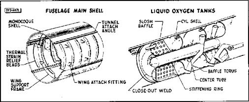
One of the innovations proposed by North American was the use of monocoque propellant tanks, leading to the use of the controversial fuselage tunnels. The forward-most part of the LOX tank was equipped with slosh baffles. (NASA)
side-stick controller that would allow the pilot’s arm to be supported by an armrest while still allowing him of full control over the aircraft.15 Coupled with the fact that there were two separate attitude-control systems on the X-15, this resulted in a unique control stick arrangement. A conventional center stick, similar to that installed in most fighter – type aircraft of the era, was connected to the aerodynamic control surfaces through a stability-augmentation (damper) system. A side – stick controller on the right console was connected to the same aerodynamic control surfaces and augmentation system. Either stick could be used interchangeably, although the flight manual16 describes using the center stick “during normal periods of longitudinal and vertical acceleration.” The center stick was occasionally omitted from flights later in the flight research program based on pilot preferences. Another side-stick controller on the left console operated the so-called “ballistic control” system17 (thrusters) that provided attitude control at high altitudes. The flight manual warns that “velocity tends to sustain itself after the stick is returned to the neutral position. A subsequent stick movement opposite to the initial one is required to cancel the original attitude change.”
At the time of the industry conference in 1956, the design for the X-15 side controller had not been definitely established but a summary of the previous experience with such controllers was available. Experimental controllers had been installed on a Grumman F9F-2, Lockheed TV-2, Convair F-102, and on a simulator. The pilots who had tried side controllers had reported no difficulty in maneuvering, but they generally felt that greater efforts would have to be made to eliminate backlash and to control friction forces; they had also urged that efforts be made to give the side controllers a more “natural” feel.
Another problem which had not been thoroughly explored at the time of the 1956 con ference concerned the proposed reaction controls that would be necessary for the X-15 as dynamic pressures decreased to the point where the aerodynamic controls would no longer be effective. Analog computer and ground simulator studies were then under way in an effort to determine the best relationship between the control thrust and the pilot’s movement of the control stick. Attempts were also being made to determine the amount of propellant that would be required for the reac-
|
|
|
|
|
|
|
|
|
|
|
|
|
|
|
|
|
|
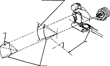
tion controls. No significant problems were uncovered during these early investigations, but it was clear that the pilot would have to give almost constant attention to such a control system and that pilots should be given extensive practice on simulators before being allowed to attempt actual flight.
Some of the anticipated difficulties in the field of instrumentation arose because available strain gauges were not considered satisfactory at the expected high temperatures and because of difficulties in recording the output of thermocouples. Large structural deformations of wings and empennage were to be recorded by cameras in special camera compartments. Another instrumentation problem arose because the sensing of static pressure, ordinarily difficult at high Mach numbers, was compounded in the case of the X-15 by heating that would be too great for any conventional probe and by the low pressure at the high altitudes to be explored. The answer was to develop a stable-platform-integrating- accelerometer system to provide velocity, altitude, pitch, yaw, and roll angle information.
Still another instrumentation difficulty was created by the desirability of presenting the
pilot with angle-of-attack and side slip information, especially for the critical exit and reentry periods. Any device to furnish this information would have to be located ahead of the aircraft’s own flow disturbances, be structurally sound at elevated temperatures, accurate at low pressures, and cause a minima) flow disturbance so as not to interfere with the heat transfer studies that were to be conducted in the forward area of the fuselage. These requirements had resulted in the design of a ball-nose16 capable of withstanding 1,200 degrees Fahrenheit. A six-inch diameter Inconel X sphere located in the extreme nose of the X-15 was gimbaled19 and servo-driven in two planes. It had five openings: a total-head port opening directly forward and two pairs of angle-sensing ports in the pitch and yaw planes, located at an angle of 30 to 40 degrees from the central port. Pitch and yaw could be sensed as pressure differences and these differences were converted into signals that would cause the servos to realign the sphere in the relative wind.
Based largely on urgings from Scott Crossfield, the Air Force agreed to allow North American to design an ejection seat and to make a study justifying the selection
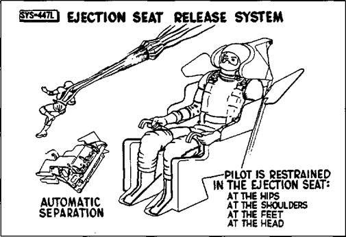 Although the ejection seat showed at the 1956 industry conference did not resemble the final unit used in the X-15s, the basic concepts remained the same. Restraining the pilot’s head, arms, and legs during ejection at high dynamic pressures presented one of the major chal-. lenges to seat development. (NASA)
of a seat in preference to a capsule system.20 Two main criteria had governed the selection of an escape system for the X-15, and these criteria were not necessarily complementary. The first requirement was that the system be the most suitable that could be designed while remaining compatible with the airplane. The second was that no system would be selected that would delay the development of the X-15 or leave the pilot without any method of escape when the time arrived for flight research. The four possible escape systems that were considered included cockpit capsules, nose capsules, a canopy shielded seat, and a stable – seat with a pressure-suit. An analysis of the expected flight hazards had indicated that because of the fuel exhaustion and low aerodynamic loads, the accident potential at peak speeds and altitudes was only about two percent of the total.
Capsule-like systems had been tried before, most notably in the X-2 where the entire forward fuselage could be detached from the rest of the aircraft. Model tests showed these to be very unstable and prone to tumble at a high rate of rotation. They also added a great deal of weight and complexity to the aircraft,21
The final decision for a stable-seat with a pressure-suit was made because most of the potential accidents could be expected to occur at speeds of Mach 4 or less, because system reliability always decreased with system complexity, and finally, because it was the system that imposed the smallest weight and size penalties upon the aircraft. The selected system would not function successfully at altitudes above 120,000 feet or speeds in excess of Mach 4, but designers, particularly Scott Crossfield, held that the aircraft itself would offer the best protection in the areas of the performance envelope where the seat-suit combination was inadequate.
Cockpit and instrument cooling, pressurization, suit ventilation, windshield defogging, and fire protection were all to be provided from a liquid nitrogen supply. Vaporization of the liquid nitrogen would keep the pilot’s environment within comfortable limits at all times. An interesting aspect of the cooling problem was an estimate that only 1.5 percent of the system’s capacity would be applied to the pilot; the remaining 98.5 percent was required for equipment. Cockpit temperatures were to be limited to no more than 150 degrees Fahrenheit, the maximum
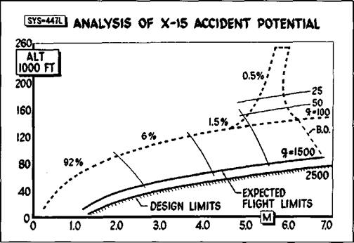 This chart shows that 92 percent of the expected X-15 accidents would happen below Mach 2 and
90,0 feet. This estimate supported Scott Crossfield’s request to use an ejection seat and pressure suit instead of a more complex escape capsule. (NASA)
limit for some of the equipment. The pilot would not be subjected to that temperature, however, as the pressure suit ventilation would enable him to select a comfortable temperature level. Cockpit pressure was to be maintained at the 35,000 foot level.
The effects of flight accelerations upon the pilot’s physiological condition and upon his ability to avoid inadvertent control movements had not been completely explored, but it was recognized that high accelerations could pose medical and restraint difficulties. In addition to the accelerations that would be encountered during the exit and reentry phases of the X-15’s flights, a very high acceleration of short duration would be produced during the landings. This was a result of the location of the main skids at the rear of the aircraft. Once the skids touched down, the entire aircraft would act as if it were hinged at the skid attachment points and the nose section would slam downward. Reproduction of this landing acceleration on simulators showed that because of the short duration, no real problem existed. There were, however, numerous complaints about the severity of the jolts both in the simulator and once actual landings began.
The final paper presented to the 1956 industry conference was an excellent summary of the development effort and a review of the major problems that were known at that time. The author, Lawrence R Greene from North American, considered flutter to be an unsolved problem, primarily because of a lack of basic data on aero-thermal-elastic relationships and because little experimental data was available on flutter at hypersonic Mach numbers. He pointed out that available data on high-speed flutter had been derived from experiments conducted at Mach 3 or less, and that not all of the data obtained at those speeds were applicable to the problems faced by the designers of the X-15. As it turned out, panel flutter was encountered early in the flight test program, leading to a change in the design criteria for high-speed aircraft. Another difficulty was the newness of Inconel X as a structural material and the necessity of experimenting with fabrication techniques that would permit its use as the primary structural material for the X-15. Problems were also expected to arise in connection with sealing materials, most of which were known to react unfavorably when subjected to high temperature conditions.22 Although North American did encounter initial problems in using Inconel
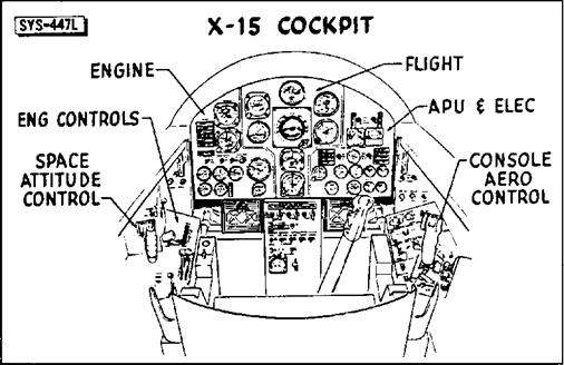 Despite its performance potential, the basic cockpit design of the X-15 was quite conventional, with the exception of the side – stick controllers. The engine instrumentation on the lower left of the instrument panel would be different for the XLR11 flights. The addition of the MH-96 in the X-15-3 would necessitate some changes in the instrumentation. See page 63 for a photo. (NASA)
X and titanium during the construction of the X-l5, it was able to work through the difficulties with no major delays.
A development engineering inspection was held at the North American Inglewood plant on 12-13 December 1956. This inspection of a full-scale tnockup was intended to reveal unsatisfactory design features before fabrication of the aircraft got under way. Thirty-four of the forty-nine individuals who participated in the inspection were representatives of the Air Force; twenty-two of them from WADC. The important role of the Air Force was also evident from the composition of the committee that would review the requests for alteration.2’ Major E. C. Freeman, of ARDC, served as committee chairman, Mr. F. Orazio of WADC and Lieutenant Colonel Keith G. Lindell of Air Force Headquarters were committee members, and Captain Chester E. McCollough, Jr. of the ARDC and Captain Iven C. Kincheloe, Jr. of the Air Force Flight Test Center (AFFTC) served as advisors. The Navy and the NACA each provided a single committee member; three additional advisors were drawn from the NACA.
The inspection committee considered 84 requests for alterations, rejected 12, and placed 22 in a category for further study. The majority of the 50 changes that were accepted were minor, such as the addition of longitudinal trim indications from the stick position and trim switches, relocation of the battery switch, removal of landing gear warning lights, rearrangement and redesign of warning lights, and improved markings for several instruments and controls.
Some of the most interesting comments were rejected by the committee. For instance, the suggestions that the aerodynamic and reaction controller motions be made similar, that the reaction controls be made operable by the same controller used for the aerodynamic controls, or that a third controller combining the functions of the aerodynamic and reaction controllers be added to the right console, were all rejected on the grounds that actual flight experience was needed with the controllers already selected before a decision could be made on worthwhile improvements or combinations. As two of the three suggestions on the controllers came from potential pilots of the X-l5 (Joseph A. Walker and
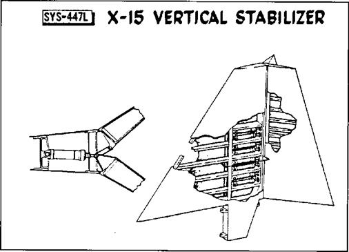 The vertical stabilizer was one of the most obvious changes between the industry conference configuration and the final vehicle. The first design did not use the exaggerated wedge-shape of the final unit. It was also more traditional, using a fixed forward portion and a conventional appearing rudder. The final version used an all-moving design. Note the rudder splits to become speed brakes, much like the shuttle design 25 years later. (NASA)
Iven C. Kincheloe, Jr.24), it would appear that the planned controllers were not all that might have been desired.
A request that the pilot be provided with continuous information on the nose-wheel door position (loss of the door could produce severe structural damage) was rejected because the committee felt that the previously approved suggestion for gear-up inspection panels would make such information unnecessary. This particular item would come back to haunt the program during the flight research phase.
After the completion of the development engineering inspection, the X-15 airframe design changed only in relatively minor details. North American essentially built the X-15 described at the industry conference in October and inspected in mockup in December 1956. Continued wind tunnel testing resulted in some external modifications, particularly of the vertical stabilizer, and some weight changes occurred as plans became more definite. But while work on the airframe progressed smoothly, with few unexpected problems, the project as a whole did encounter difficulties, some of them serious enough to threaten long delays. In fact, North American’s rapid preparation of drawings and production planning served to highlight the lack of progress on some of the components and subsystems that were essential to the success of the program.


