Category Apollo Saturn V News Reference

INSTRUMENT UNIT FACT SHEET

image130
image131

DIAMETER: 260 in.

HEIGHT: 36 in.

WEIGHT: 4,500 lb. (approx.)

MAJOR SYSTEMS

ENVIRONMENTAL CONTROL SYSTEM: Provides cooling for electronic modules and

components within the IU and forward compartments of third stage

GUIDANCE AND CONTROL SYSTEM: Determines course of Saturn V through space

and adapts that course to fulfill mission requirements

INSTRUMENTATION SYSTEM: Measures vehicle conditions and reactions during

mission and transmits this information to ground for subsequent analysis,

as well as providing for ground station-to-vehicle communication

ELECTRICAL SYSTEM: Provides basic operating power for all electronic and

electrical equipment in the IU; also monitors vehicle performance and

may initiate automatic mission abort if an emergency arises

STRUCTURAL SYSTEM: Serves as a load bearing part

of the launch vehicle, supporting both the components

within the IU and the spacecraft; composed of three

120-degree segments of thin-wall aluminum alloy face

sheets bonded over a core of aluminum honeycomb

about an inch thick

image132

SATURN V NEWS

num honeycomb. An aluminum alloy channel ring, bonded to the top and bottom edge of each segment, provides mating surfaces between the IU, the third stage, and the payload adapter. Mounted, inner skin brackets provide attachment points for the en­vironmental control system’s cold plates or for cold plate installation.

Segments are aligned and joined by splice plates bolted both inside and outside the joints. A spring – loaded umbilical door provides access to electrical connections between IU equipment and ground test areas. A larger access door, bolted in place, permits personnel to enter the IU after vehicle mating.

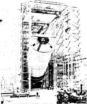
Assembly of an IU begins when the three curved structural segments, three feet high by 14 feet long, arrive at IBM’s Huntsville, Ala., facility. Each segment weighs only 140 pounds.

image133

IBM-DR-22

REFERENCE

structure. Components are mounted on the cold plates and ECS system pumps, storage tanks (called accumulators), heat exchangers, and plumbing are installed. Two nitrogen supply systems are installed: one for gas bearings of the inertial platform and the other for pressurization of the ECS. Finally, ducts, tubing, and electrical cables complete the assembly and the IU now weighing in excess of 4,000 pounds is ready for a long series of tests.

MOBILE LAUNCHER

The mobile launcher is a movable launch platform with an integral umbilical tower. The launcher base

image186

K-107-66PC-91

Arrival to Launch Pad—The facilities vehicle arrives at Launch Complex 39A.

Подпись: SATURN V NEWS REFERENCE
is a two-story steel structure covering more than half an acre. The 380-foot tower, which supports the electrical servicing and fluid lines for the ve­hicle, is a steel structure mounted on the base. The base and tower weigh 10.5 million pounds and stand 445 feet above ground level.

Among major considerations in design of the mobile launcher were crew safety and escape provisions

and protection of the platform and its equipment from blast and sonic damage.

Personnel may be evacuated from upper work levels of the umbilical tower by a high speed elevator, descending at 600 feet per minute. After leaving the elevator, they can drop through a flexible metal chute into a blast and heatproof room inside the base of the pad hardstand.

The mobile launcher provides physical support and is a major facility for checkout of the space vehicle from assembly at the VAB until liftoff at the launch

site.

The top level of the launcher base houses digital acquisition units, computer systems, controls for actuation of service arms, communications equip­ment, water deluge panels, and other control units. Included in the lower level are hydraulic charging units, environmental control systems, electrical measuring equipment, and a terminal room for in­strumentation and communications interface. Mounted on the top deck of the base are four vehicle holddown and support arms and three tail service masts.

The umbilical tower is an open steel structure pro­viding support for nine umbilical service arms, 18 work and access platforms, and, for propellant, pneumatic, electrical, water, communications, and other service lines required to sustain the vehicle. A 250-ton capacity hammerhead crane is mounted atop the umbilical tower.

The launcher restrains the vehicle for approximately 5 seconds after ignition to allow thrust buildup and verification of full thrust from all engines. The design “up-load” during the holddown period is 3 million pounds. If one or more of the engines fail to develop full thrust, the vehicle is not released, and all engines automatically are shut down.

Подпись: K-107-66PC-63

Подпись: 8-15

Night Shot—A 365-foot-tall Saturn V facilities vehicle Is shown in place at Launch Pad 39A.

SATURN V NEWS REFERENCE

. LOX Tank

The 331,000-gallon liquid oxygen tank is the largest component of the first stage booster, standing more than 64 feet in height. Its content is 297 degrees below zero Fahrenheit and provides the oxidizer to support combustion of the kerosene. Mixing of the two propellants is in a proportion to ensure complete combustion. Each second during flight, the engines consume more than 2,000 gallons of liquid oxygen.

image22

В 8219-3

LOX Tank… The completed 331,000-gallon LOX tank is being

carried to the hydrostatic testing facility where it will be tested for leaks.

The LOX tank’s construction is similar to that of the fuel tank with the LOX tunnels beginning at the tank base, running through the intertank and fuel tank and to the engines. Dry weight of the LOX tank exceeds 19 tons.

Intertank

The intertank is not a tank in itself but serves as a 6-1/2-ton link between fuel and LOX tanks. Its composition is 18 corrugated skin panels supported by five frame ring assemblies.

The lower bulkhead of the LOX tank dips into the intertank while the upper bulkhead of the fuel tank extends upward into the intertank. Around the edges of the intertank are attached 216 fittings, which fasten the tank together with the Y-rings of the fuel and LOX tanks. The intertank structure also contains a personnel access door.

Umbilical Openings

An umbilical opening in the intertank provides for electrical and instrumentation requirements, emergency LOX drain, line pressurization, elec­trical conduit, and provisions for venting internal pressure. The thrust structure contains three of four other umbilical openings on the booster. The fourth is located in the forward skirt. The thrust structure umbilicals carry the fuel line, liquid oxygen drain, ground supply fluid lines, and all control functions essential in case of a vehicle abort.

image23

B-5773-6

LOX Tunnel… Five 42-foot tunnels bring liquid oxygen from

the LOX tank through the fuel tank and to the engines. Here a tunnel is being fitted into the fuel tank.


image24

A Completed Intertank


2-3


. LOX Tank

image26

В 2835 34


B-6733-3


Fin and Fairing Assembly–Fairings are fitted over each of the outboard engines to smooth the air flow. Fins are attached to the fairings.

image29

B-9580-8


Forward Skirt–The structural link between the LOX tank and the engine shroud of the second stage is shown being lowered for dimensional inspection.

FIRST STAGE FLIGHT

The first stage is loaded with RP-1 fuel and LOX at approximately 12 and 4 hours respectively, be­fore launch. With all systems in a ready condition, the stage is ignited by sending a start signal to the five F-l rocket engines. The engine main LOX valves open first allowing LOX to begin to enter the main thrust chamber. Next the engines’ gas generators and turbopumps are started. Each en­gine’s turbopump assembly will develop approx­imately 60,000 horsepower. Combustion is initiated by injecting a hypergolic solution into the engine’s main thrust chamber to react with the LOX already present. The main fuel valves then open, and fuel enters the combustion chamber to sustain the re­action previously initiated by the LOX and hyper­golic solution. Engine thrust then rapidly builds up to full level. The five engines are started in a 1-2-2 sequence, the center engine first and opposing out­board pairs at 300-millisecond stagger times. The stage is held down while the engines build up full thrust. After full thrust is reached and all engines and stage systems are functioning properly, the stage is released. This is accomplished by a “soft release” mechanism. First, the restraining hold­down arms are released. Immediately thereafter the vehicle begins to ascend but with a restraining force caused by tapered metal pins being pulled through holes. This “soft release” lasts for about 500 milliseconds.

SATURN V NEWS REFERENCE

The vehicle rises vertically to an altitude of approx­imately 430 feet to clear the launch umbilical tower and then begins a pitch and roll maneuver to attain the correct flight azimuth. As the vehicle continues its flight, its path is controlled by gimbaling the outboard F-l engines consistent with a prepro­grammed flight path and commanded by the instru­ment unit.

At approximately 09 seconds into the flight, the vehicle experiences a condition of maximum dy­namic pressure. At this time, the restraining drag force is approximately equal to 400,000 pounds.

At 135.5 seconds into the flight most of the LOX and fuel will be consumed, and a signal is sent from the instrument unit to shut down the center engine. The outboard engines continue to burn until either LOX or fuel depletion is sensed. LOX depletion is signaled w’hen a “dry” indication is received from at least two of the four LOX cutoff sensors; one sensor is located near the top of each outboard LOX suction duct. Fuel depletion is signaled by a “dry” indication from a redundant fuel cutoff sensor bolted directly to the fuel tank lower bulkhead. The LOX depletion cutoff is the main cutoff system with fuel cutoff as the backup.

Six hundred milliseconds after the outboard engines receive a cutoff signal, a signal is given to fire the first stage retrorockets. Eight retroroekets are pro­vided and each produces an average effective thrust of 88,600 pounds for 0.666 seconds. The first stage separates from the second stage at an altitude of about 205,000 feet. It then ascends to a peak altitude near 366,000 feet before beginning its descent. While falling, the stage assumes a semistable en­gines down position and impacts into the Atlantic Ocean at approximately 350 miles down range of Cape Kennedy.

^ SATURN V NEWS REFERENCE

F-l ENGINE FACT SHEET

image56image57

Подпись: NOTE: E-l engine will be uprated to 1,522,000 ib. thrust for Vehicle 504 and all subsequent operational vehicles.

LENGTH

WIDTH

THRUST (sea level)

SPECIFIC IMPULSE (minimum)

RATED RUN DURATION FLOWRATE: Oxidizer Fuel

MIXTURE RATIO CHAMBER PRESSURE WEIGHT FLIGHT CONFIGURATION EXPANSION AREA RATIO

COMBUSTION TEMPERATURE: Thrust Chamber

Gas Generator

MAXIMUM NOZZLE EXIT DIAMETER

19 ft.

12 (t. 4 in.

1.500,0 lb.

260 sec.

150 sec.

3,945 lb. sec. (24,811 gpm) 1,738 lb. sec. (15,471 gpm) 2,27:1 oxidizer to fuel 965 psia

18,500 lb. maximum

16:1 with nozzle extension

10:1 without nozzle extension

5,970°F

1,465°F

11 ft. 7 in,

^ SATURN V NEWS REFERENCE

STRUCTURE

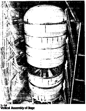
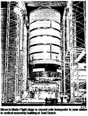
The second stage structure consists of an inter­stage, which links it with the first stage; a thrust structure and aft skirt assembly, which supports and houses the five J-2 engines; an ellipsoidal liquid oxygen tank; a bolting ring, which attaches the liquid oxygen tank to the second stage structure; six aluminum cylinder walls, which are welded

4-1


image71

Подпись: SATURN V NEWS REFERENCE
image73

Stacking Stage—Aft skirt, thrust structure, and common bulk­head move on transfer table to new station for further buildup of stage.

lower ring. Four support rings along with an outer skin stiffened with hat sections comprise the basic structure. In addition, eight thrust longerons (two to each panel) extend upward along the conical surface of the thrust structure. The lower circum­ferential ring rests directly over the line of thrust of each of the four outboard engines while the cen­ter engine support beam assembly is directly over the thrust line of the center engine. A rigid heat shield mounted around the five J-2 engine •• to a frame connecting to the thrust structure protects the base area of the stage against recirculation of hot engine exhaust gases and heat from the ex­haust. This heat shield is of lightweight construc­tion protected by low-density ablative (heat-resis­tant) material.

Although assembled separately, the aft skirt and thrust structure when joined become a structural entity and together support the five engines and withstand and distribute the thrust and boost struc­tural loads.

In ado, tion to engines and engine accessories, the
interstage, aft skirt, and thrust structure house electrical and mechanical equipment such as signal conditioners and controllers, telemetry electronics, flight control electronics, service and connecting umbilicals, electrical power control units, power distribution panels and batteries, inverters, propel­lant management electronics, propellant plumb­ing, ordnance installations, and hydraulic pumps and accumulators. Equipment that is not required after second-plane separation is in the interstage which is separated 30 seconds after ignition. Equipment necessary for flight operations is located on the aft skirt, thrust structure, and forward skirt.

HYDRAULIC SYSTEM

The hydraulic system performs engine positioning upon command from the IU. Major components are a J-2 engine-driven hydraulic pump, two hydraulic actuator assemblies, and an accumulator-reservoir assembly.

image112

J-2 Engine Hydraulic System Components

The electrically driven auxiliary hydraulic pump is started before vehicle liftoff to pressurize the hy­draulic system. Electric power for the pump is provided by a ground source. At liftoff, the pump is switched to stage battery power. Pressurization of the hydraulic system restrains the J-2 engine in a null position with relation to the third stage eenter-

REFERENCE

line, preventing pendulum-like shifting from forces encountered during liftoff and boost. During power­ed flight, the J-2 engine may be gimbaled up to 7° in a square pattern by the hydraulic system upon command from the IU.

Engine-Driven Hydraulic Pump

The engine-driven hydraulic pump is a variable dis­placement type pump capable of delivering hy­draulic fluid under continuous system pressure and varying volume as required for operation of the hy­draulic actuator assemblies. The pump is driven directly from the engine oxidizer turbopump. A thermal isolator in the system controls hydraulic – fluid temperature to ensure proper operation.

Auxiliary Hydraulic Pump

The auxiliary hydraulic pump is an electrically driven variable displacement pump which supplies a constant minimum supply of hydraulic fluid to the hydraulic system at all times. The pump is also used to perform preflight engine gimbaling check­outs, hydraulically lock the engine in the null posi­tion during boost phase, maintain system hydraulic – fluid at operating temperatures during other than the powered phase, and augment the engine-driven hydraulic pump during powered flight. It also pro­vides an emergency backup supply of fluid to the system.

Hydraulic Actuator Assemblies

Two hydraulic actuator assemblies are attached directly to the J-2 engine and the thrust structure and receive IU command signals to gimba! the en­gine. The actuator assemblies are identical and interchangeable.

Accumulator-Reservoir Assembly

The accumulator-reservoir assembly is an integral unit mounted on the thrust structure. The reservoir section is the storage area for hydraulic fluid; the accumulator section supplies peak system fluid re­quirements and dampens high-pressure surges with­in the system.

INSTRUMENT UNIT SYSTEMS Environmental Control System

The ECS cools the electronic equipment in the IU and the forward third stage skirt. Sixteen cold plates are installed in each stage.

An antifreeze-like coolant, 60 per cent methanol and 40 per cent water, from a reservoir within the IU is circulated through the cold plates. Heat gen­erated by the mounted components is transferred to the coolant by means of conduction.

Prior to liftoff a preflight heat exchanger serviced by ground support equipment transfers heat from the coolant. Approximately 163 seconds after lift­off, ECS’s sublimator-heat exchanger takes over the job of temperature control.

Some of the more complex components like the guidance computer, flight control computer, and the ST-124-M platform, have coolant fluid circulated through them to provide more efficient heat removal.

In the vacuum of space the warmed coolant, after leaving the cold plates, is routed through a device called a sublimator. Water, from an IU reservoir,

Structure Segments—Prior to splicing, mounting brackets for thermal conditioning panels can be seen on interior surface of segments. The exterior of the spring-loaded umbilical door and the access door are visible at right center.

Extremely accurate theodolites, similar to a sur­veyor’s transit, are used to align the segments in a circle prior to splicing. Metal splicing plates join the three segments, and the holes which permit the IU to be joined to mating surfaces of the launch vehicle are drilled at top and bottom edges of the structure for ease in handling. Protective rings are bolted to these edges to stiffen the structure. Vehicle antenna holes are cut after splices are bolted.

After structure fabrication is completed, module and component assembly operations begin. Tem­perature transducers are fastened to the inner skin, environmental control system (ECS) cold plates are mounted, and a cable tray is bolted to the top of the

7- 2

image134

Splice Joint Operations—Final grinding of a splice joint ensures a smooth surface prior to splice plate assembly.

SATURN V NEWS

goes to the sublimator and is exposed through a porous plate to the low temperature and pressure of outer space where it freezes, blocking the pores in the plate. The heat from the coolant, transferred to the plate, is absorbed by the ice converting it directly into water vapor (a process called sub­limation).

The system is self-regulating. The rate of heat dis­sipation varies with the amount of heat input, speed­ing up or slowing down as heat is generated. If the coolant temperature falls below a pre-set level, an

image135

IBM-DR-19

Instrument Unit Assembly in IBM Manufacturing Area – Splicing operations and assembly of the tubular cable tray are complete, the cold plates have been installed, and installation of com­ponents is underway.

image136

IBM-DR-21

image137

REFERENCE

IBM-DR-23

Environment Control—A mobile clean room protects against contamination during assembly of environmental control system components. Gaseous nitrogen will be circulated from a ground supply through the duct partially assembled in the cable tray to purge the IU following vehicle fueling.

electronically controlled valve causes the coolant mixture to bypass the sublimator until the tem­perature rises sufficiently to require further cooling.

Nitrogen gas provides artificial pressure for both coolant solution and sublimator water reservoirs during orbit.

A coolant circulating pump along with the necessary valves and piping to control flow complete the en­vironmental control equipment.

Guidance and Control

Подпись:

Подпись: IBM.DR-8 Block Diagram of Guidance and Control System 7-3

The IU’s guidance and flight control systems nav-

image138

SATURN V NEWS

igate (determine vehicle position and velocity), guide (determine attitude correction signals), and control (determine and issue control commands to the engine actuators) the Saturn V vehicle.

Completely self-contained, these systems measure acceleration and vehicle attitude, determine velocity and position and their effect on the mission, cal­culate attitude correction signals, and determine

and issue control commands to the engine actuators.

All this is done to place the vehicle in a desired attitude to reach the required velocity and altitude for mission completion.

Major components are an inertial platform, the launch vehicle digital computer (LVDC), the launch vehicle data adapter (LVDA), an analog flight con­trol computer, and control and rate gyros.

image139

IBM-DR-4

ST-124-M Inertia! Platform System

Prior to liftoff, launch parameters go to the LVDC.

About five seconds before liftoff, the inertial guid­ance platform and the LVDC are released from ground control. As the vehicle ascends, the guid­ance platform senses and measures vehicle accel­eration and attitude and sends these measurements to the LVDC via the LVDA.

The LVDC integrates these measurements with the time since launch to determine vehicle position relative to starting point and destination. It then computes the desired vehicle attitude, using data stored in its memory, and the difference between the desired attitude and the actual becomes the generated attitude correction signal.

This signal is sent to the analog flight control com­puter, where it is combined with information from rate gyros. Using this data, the flight control com­puter determines and issues the command to gimbal the engines and change the thrust direction.

Each mission has at least three phases: atmospheric – powered flight, boost period after initial entry into

7-4

REFERENCE

space, and the coasting period.

Atmospheric boost causes the greatest vehicle load because of atmospheric pressure. During this time the guidance system is primarily checking vehicle integrity and is programmed to minimize this pres­sure.

image140

IBM-DR-6

Guidance and Control—The LVDC and LVDA portion of the guidance system is shown in this block diagram. The LVDC receives information from all parts of the vehicle via the LVDA, and in turn issues commands.

The vehicle maintains liftoff orientation long enough to clear the launch equipment, and then it performs a roll maneuver to get to the flight azimuth direc­tion.

The time tilt program is applied after the roll ma­neuver. The pitch angle is regulated by the tilt program, and is independent of navigation measure­ments. However, navigation measurements and computations are performed throughout the flight, beginning at the time the platform is released (i. e., five seconds before liftoff). First stage engine cut­off and stage separation are commanded when the IU receives a signal that the tank’s fuel level has reached a predetermined point. During second stage powered flight the LVDC guides the vehicle via the best path to reach the mission objectives.

During orbit, navigation and guidance information in the LVDC can be updated by data transmission from ground stations through the IU radio com­mand system.

Approximately once every two seconds, the LVDC, using iterative or "closed loop” guidance, figures vehicle position and vehicle conditions required at the end of powered flight (velocity, altitude, etc.) and generates the attitude correction signals to gimbal the engines so that the vehicle reaches its predetermined parking orbit.

Подпись: SATURN V NEWS REFERENCE

Подпись:image143III Interior During Assembly—The large, cylindrical component simulates size and shape of the flight control computer and is used to check cable lengths and mounting arrangement.

Second stage engine cutoff comes when the IU is signaled that stage propellant has reached a pre­determined level, and then the stage is separated. By this time, the vehicle has already reached its approximate orbital altitude, and the third stage burn merely gives it enough push to reach a cir­cular parking orbit.

TESTING

INTRODUCTION

The expense of the Saturn V makes it imperative that no effort be spared to assure that it will per­form as expected in flight. The magnitude of the Saturn V ground test program, therefore, is un­precedented. To qualify for flight, all components and systems must meet standards deliberately set much higher than actually required. This margin of safety is built into all manrated space hardware.

Compared with earlier rocket programs the ground testing on Saturn V is more extensive and the flight testing is shorter. The ground test programs con­ducted on the F-l and J-2 engines, which power the three stages, offer an example of the thoroughness of this testing effort. The J-2 has been fired some 2,500 times on the ground, for a total running time of more than 63 hours. The F-l has been fired more than 3,000 times for a running time of more than 43 hours.

Further, in earlier rocket programs such as Red­stone, Thor, and Jupiter, 30 to 40 R&D flight tests were standard. In the Saturn I program, where more emphasis was placed on ground testing prior to the flight phase, 10 R&D flight tests were planned. The vehicle was declared operational after the first six firings met with success.

The Uprated Saturn I (Saturn IB) —an improve­ment on the basic Saturn I —was manrated after three flights. On the Saturn V, only two flights are planned prior to the attainment of a "manned con­figuration.”

The inspection to which flight hardware is subjected is thorough. Following are examples of many steps which are taken to inspect the Saturn V vehicle:

1. X-rays are used to scan fusion welds, 100 cast­ings, and 5,000 transistors and diodes.

2. A quarter mile of welding and 5 miles of tubing are inspected with the use of a sound technique (ultrasonics). The same type of inspection is given to adhesive bonds, which are equivalent in area to an acre.

3. An electrical current inspection method is used on 6 miles of tubing, and dye penetrant tests are run on 2.5 miles of welding.

Each contractor has his own test program that is patterned to a rather basic conservative approach. It begins with research to verify specific principles to be applied and materials to be used. After pro­duction starts each contractor puts flight hardware through qualification testing, reliability testing, development testing, acceptance testing, and flight testing.

QUALIFICATION TESTING

Qualification testing of parts, subassemblies, and assemblies is performed to assure that they are capable of meeting flight requirements. Tests under the conditions of vibration, high-intensity sound, heat, and cold are included.

RELIABILITY TESTING

Reliability analysis is conducted on rocket parts and assemblies to determine the range of failures or margins of error in each component. Reliability information is gathered and shared by the rocket industry.

DEVELOPMENT TESTING

A battleship test stage constructed more solidly than a flight stage is often used to prove major design parameters within a stage. Such a vehicle verifies propellant loading, tank and feed operation, and engine firing techniques.

Battleship testing is followed by all-systems test­ing. For example, one of four ground test stages of the first stage completed 15 firings at Marshall Space Flight Center in Huntsville. The firings proved that the design and fabrication of the complete booster and of its subsystems were adequate.

The entire Apollo/Saturn V vehicle, consisting of the three Saturn V propulsive stages, the instru­ment unit, and an Apollo spacecraft, was assembled in the Dynamic Test Stand at the Marshall Center. This is the only place, aside from the launch site, where the entire Saturn V vehicle has been assem­bled. The purpose of dynamic testing was to deter­mine the bending and vibration characteristics of the vehicle to verify the control system design. The 364-foot assembly was placed on a hydraulic bearing or “floating platform”. Electromechanical shakers caused the vehicle to vibrate, simulating the response expected from flight forces.

Fins and Failings

Four fairings attach to the thrust structure and partially surround the outboard engines at the foot of the booster. They house the eight retrorockets and the actuator support structures. Fairings are shaped like cone halves and are constructed of alu­minum. Their purpose is to smooth the air flow over the engines.

The fins are airfoil attachments to the fairings. Fins are rigid and add to the vehicle’s flight stabil­ity. A titanium skin covers the fin for greatest protection against temperatures as high as 2,000 degrees Fahrenheit.

Each of the eight retrorockets generates about 86,600 pounds of thrust for two-thirds of a second


Michoud Manufacturing Area—In the foreground of this Michaud plant view, fairings are being assembled.


2-4


image27image28

SATURN V NEWS REFERENCE

image30

Tube and Valve Cleaning Vat – Each stage component is treated in a cleaning solution before final assembly.

F-l ENGINE

ENGINE DESCRIPTION

The F-1 engine is a single-start. 1,500.000-pound fixed-thrust, bipropeliant rocket system. The en­gine uses liquid oxygen as the oxidizer and RP-1 (keroseneI as fuel. The engine is bell-shaped, with an area expansion ratio—the ratio of the area of the throat to the base—of Hi:L RP-1 and LOX are com­bined and burned in the engine’s thrust chamber as­sembly. The burning gases are expelled through an expansion nozzle to produce thrust. The five-engine cluster used on the first stage of the Saturn V pro­duces 7.500,000 pounds of thrust. All of the engines are identical with one exception. The four outboard engines gimbal; the center engine does not.

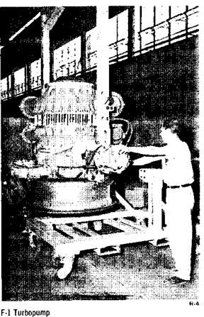
The major engine systems are the thrust chamber assembly, the propellant feed system, the turbo-

image58

Assembly Thrust chambers of the F-i rocket engine—the most powerful engine under development by the United States – are assembled in this manufacturing line.

pump, the gas generator system, the propellant tank pressurization system, the electrical system, the hydraulic control system, and the flight instru­mentation system.

THRUST CHAMBER ASSEMBLY

The thrust chamber assembly consists of a gimbal bearing, an oxidizer dome, an injector, a thrust chamber body, a thrust chamber nozzle extension, and thermal insulation. The thrust chamber as­sembly receives propellants under pressure sup­plied by the turbopump, mixes and burns them, and imparts a high velocity to the expelled combus­tion gases to produce thrust. The thrust chamber assembly also serves as a mount or support for all engine hardware.

Gimbal Bearing

The gimbal bearing secures the thrust chamber assembly to the vehicle thrust frame and is mounted on the oxidizer dome. The gimbal is a spherical, universal joint consisting of a socket-type bearing with a bonded Teflon-fiberglass insert which pro­vides a low-friction bearing surface. It permits a maximum pivotal movement of <i degrees in each direction of both the X and Zaxes (roughly analogous to pitch and yaw! to facilitate thrust vector control. The gimbal transmits engine thrust to the vehicle and provides capability for positioning and thrust alignment.