Electrical System
The electrical power and distribution system of the
first stage provides power for controlling and measuring functions of the vehicle. The system operates during static firing, launch preparation and checkout. launch, and flight.
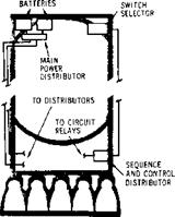
The electrical system consists of two batteries, a main power distributor, a sequence and control distributor, propulsion distributor, timer distributor. measuring distributors, thrust OK distributor, and measuring power distributor.
Two independent 28-volt DC power systems are installed on the stage. System No. 1, the main power battery, energizes the stage controls. The battery has a 640-ampere-minute rating, weighs about 22 pounds, and is used to control various solenoids. Battery No. 2, the instrumentation battery, energizes the flight measurement system and gives power to redundant systems for greater mission reliability. It has a 1,250-ampere-minute rating and weighs approximately 55 pounds. The range safety system can be operated by either battery.
Preflight power is supplied from ground equipment through umbilical connections. The supply for each system is 28 volts. Ground sources supply power for heaters, ignitors, and valve operators that are not operated during flight.
The distributors subdivide the electrical circuits and serve as junction boxes. Both electrical systems share the same distributors. The main power distributor houses relays, the power transfer switch, and electrical distribution buses. The relays control circuits that must be time-programmed. The motor-operated, multi-contact, power transfer switch transfers the stage load from the ground supply to the stage batteries. The transfer is tried several times during countdown to verify operation. Power is distributed by the main buses.
|
Electrical System |
The switch selector, actuated by the instrument unit (IU), commands the sequence and control distributor, which in turn amplifies the signals received. The sequence and control distributor then energizes the various circuit relays required to implement the flight program. The switch selector is an assembly of redundant low power relays and transistor switches, which control the sequence and control distributor. It is activated by a coded signal from the instrument unit computer.
The propulsion distributor contains the monitor and control circuits for the propulsion system.
The thrust OK distributor contains the circuits that shut down the engines when developed thrust is inadequate. Two of the three thrust OK switches must operate or the engine will be shut down.
The timer distributor houses the circuits to delay the operation of relay valves and other electromechanical devices. The programmed delays are essential for optimum performance and safety.
The measuring power distributor contains electrical buses, and the measuring distributors route data from measuring racks, serve as measurement signal junction boxes, and switch data between the hardwire and telemetry.


