Category Apollo Saturn V News Reference

Gas Generator and Exhaust System

This system consists of the gas generator, gas gen­erator control valve, turbine exhaust system and exhaust manifold, heat exchanger, and oxidizer turbine bypass valve.

GAS GENERATOR

The gas generator is welded to the fuel pump tur­bine manifold, making it an integral part of the fuel turbopump assembly. It produces hot gases to drive the fuel and oxidizer turbines and consists of a combustor containing two spark plugs, a control valve containing fuel and oxidizer ports, and an in­jector assembly.

When engine start is initiated, the spark exciters in the electrical control package are energized, pro­viding energy to the spark plugs in the gas genera­tor combustor. Propellants flow’ through the con­trol valve to the injector assembly and into the com­bustor outlet and are directed to the fuel turbine and then to the oxidizer turbine.

GAS GENERATOR CONTROL VALVE

The gas generator control valve is a pneumatically operated poppet-type that is spring-loaded to the closed position. The fuel and oxidizer poppets are mechanically linked by an actuator. The gas genera­tor control valve controls the flow of propellants through the gas generator injector.

When the mainstage signal is received, pneumatic pressure is applied against the gas generator con­trol valve actuator assembly which moves the piston and opens the fuel poppet. During the fuel poppet opening, an actuator contacts the piston that opens the oxidizer poppet. As the opening pneumatic pres­sure decays, spring loads close the poppets.

TURBINE EXHAUST SYSTEM

The turbine exhaust ducting and turbine exhaust
hoods are of welded sheet metal construction. Flanges utilizing dual (Naflex) seals are used at component connections. The exhaust ducting con­ducts turbine exhaust gases to the thrust chamber exhaust manifold which encircles the thrust cham­ber approximately halfway between the throat and the nozzle exit. Exhaust gases pass through the heat exchanger and exhaust into the main thrust chamber through 180 triangular openings between the tubes of the thrust chamber.

HEAT EXCHANGER

The heat exchanger is a shell assembly, consisting of a duct, bellows, flanges, and coils. It is mounted in the turbine exhaust duct between the oxidizer turbine discharge manifold and the thrust chamber. It heats and expands helium gas for use in the third stage or converts liquid oxygen to gaseous oxygen for the second stage for maintaining vehicle oxi­dizer tank pressurization. During. engine operation, either liquid oxygen is tapped off the oxidizer high – pressure duct or helium is provided from the ve­hicle stage and routed to the heat exchanger coils.

OXIDIZER TURBINE BYPASS VALVE

The oxidizer turbine bypass valve is a normally open, spring-loaded, gate type. It is mounted in the oxidizer turbine bypass duct. The valve gate is equipped w’ith a nozzle, the size of which is deter­mined during engine calibration. The valve in its open position depresses the speed of the oxygen pump during start, and in its closed position acts as a calibration device for the turbopump perform­ance balance.

Control System

The control system includes a pneumatic system and a solid-state electrical sequence controller pack­aged with spark exciters for the gas generator and the thrust chamber spark plugs, plus interconnect­ing electrical cabling and pneumatic lines.

PNEUMATIC SYSTEM

The pneumatic system consists of a high-pressure helium gas storage tank, a regulator to reduce the pressure to a usable level, and electrical solenoid control valves to direct the central gas to the vari­ous pneumatically controlled valves.

LAUNCH CONTROL CENTER

Located Southeast of the VAB is the launch control center (LCC). This four-story building is the elec-

image178

K-107-66PC-75

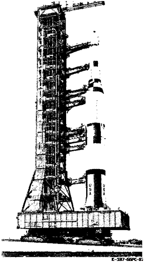
Saturn V Facilities Vehicle Rollout at Kennedy Space Center

8-Ю


SATURN V NEWS REFERENCE

Подпись: The RCA 110A computer is capable of transmitting Vehicle Assembly Building at KSC Viewed From Across the 2,016 discrete signals to the vehicle where it is Turning Basin of Launch Complex 39
Подпись: 811

tronic brain of Launch Complex 39. Here final count­down and launch of Saturn V’s will be conducted. The LCC is also the facility from which a multitude of checkout and test operations will be conducted while space vehicle assembly is taking place inside the VAB.

Two separate, automated computer systems are used to check out and conduct the countdown for the Saturn V. The acceptance checkout equipment, or ACE, is used for the Apollo spacecraft. The Saturn ground computer system is used for the various stages of the vehicle.

Located in the launch control center is the heart of the Saturn ground computer system. Here check­out and preflight countdown are conducted.

This system has as its “brain" two RCA 110A com­puters. One is located in the launch control center and the other is in the mobile launcher upon which the Saturn V is erected.

image179

K-100-66C-813

Moving Tower-Personnel watch a mobile launch tower moving along the crawlerway at Kennedy Space Center.

Through the process control system, all stages are checked, and data from the engines and from the guidance, flight control, propellants, measurement, and telemetry systems is provided.

The Saturn ground computer system also includes a DDP 224 display computer located in the LCC. It can drive up to 20 visual cathode ray display tubes.

possible for the computer in the mobile launcher to return 1,512 discrete signals.

A digital data acceptance system collects and makes available onboard analog data to the computers.

A triply redundant system for discrete output in­formation allows more reliability. There are 1,512 signals going to the mobile launcher showing "on” and “off” commands. If one signal fails or reports a wrong command and the other two signals trans­mit another command, the majority command is indicated in the display and transmitted to the vehicle.

There are 15 display systems in each LCC firing room, with each system capable of giving digital information instantaneously.

Sixty television cameras are positioned around the Saturn V transmitting pictures on 10 channels.

Additionally, the LCC contains several hundred operational intercommunication channels which en­able the launch team and the launch director to be in voice contact with the astronauts aboard the spacecraft.

Automatic checkout of the Apollo spacecraft is ac­complished through acceptance checkout equipment (ACE). Through the use of computers, display con­soles, and recording equipment, ACE provides an instantaneous, accurate method of spacecraft pre­flight testing. ACE also is used at the spacecraft contractor plants and in testing at the Manned Spacecraft Center in Houston.

image180

SATURN V NEWS

REFERENCE

Computerized checkout of the Saturn stages at the launch pad and the Apollo ACE system at the Man­ned Spacecraft Operations Building at the Kennedy Space Center are tied together by instrumentation.

The Saturn V employs completely automated com­puter controlled checkout systems for each of its stages. The system uses a carefully detailed com­puter program and associated electronic equipment to perform a complete countdown checkout of each stage and all its various systems, subsystems, and components.

With electronic speed, it moves through a thorough and reliable countdown, yet permits test engineers to monitor every step of the operation and to over­ride the computer functions, if necessary.

To monitor fuel and oxidizer mass for the three stages of the Saturn V vehicle, a propellant tanking computer system (PTCS) is used. This system con­trols propellant tank fill and replenishment. Liquid oxygen and liquid hydrogen must be replenished constantly to compensate for boil-off.

TYPICAL LUNAR LANDING MISSION

The jumping-off place for a trip to the moon is NASA’s Launch Complex 39 at the Kennedy Space Center. After the propellants are loaded, the three astronauts will enter the spacecraft and check out their equipment.

While the astronauts tick off the last minutes of the countdown in the command module, a large crew in the launch control center handles the complicated launch operations. For the last two minutes, the countdown is fully automatic.

At the end of countdown, the five F-l engines in the first stage ignite, producing 7.3 million pounds of thrust. The holddown arms release the vehicle, and three astronauts begin their ride to the moon.

Turhopumps, working together with the strength of 31) diesel locomotives, force 15 tons of fuel per second into the engines. Steadily increasing accel­
eration pushes the astronauts back into their couch­es as the rocket generates 1-1, If times the force of earth gravity.

After 2,5 minutes, the first stage has burned its

4,192,0 pounds of propellants and is discarded at about 38 miles altitude. The second stage’s five,1-2 engines are ignited. Speed at this moment is 5,330 miles per hour.

The second stage’s five 4-2 engines burn for about (5 minutes, pushing the Apollo spacecraft to an altitude of nearly 115 miles and near orbital velocity of 15,300 miles per hour. After burnout the second stage drops away and retrorockets slow it for its fall into the Atlantic Ocean west of Africa.

image6

The single 4-2 engine in the third stage now ignites and burns for 2.75 minutes. This brief burn boosts the spacecraft to orbital velocity, about 17,500 miles an hour. The spacecraft, with the third stage still attached, goes into orbit about 12 minutes after liftoff. Propellants in the third stage are not depleted when the engine is shut down. This stage stays with the spacecraft in earth orbit, for its en­gine will be needed again.

Подпись: SATURN V NEWS REFERENCE
Подпись: K-107P-66P-258 Throughout the launch phase of the mission, telem­etry systems are transmitting continously, track­ing systems are locked on, and voice communica­tions are used to keep in touch with the astronauts. All stage separations and engine thrust terminations are reported to the Mission Control Center at Houston.

The astronauts are now in a weightless condition as they circle the earth in a “parking orbit” until the timing is right for the next step to the moon.

The first attempt at a lunar landing is planned as an “open-ended” mission with detailed plans at every stage for mission termination if necessary. A comprehensive set of alternate flight plans will be laid out and fully rehearsed for use if such a de­cision should prove necessary. For example, a de­cision might be made in the earth parking ortm not to continue with the mission. At every stage of the mission, right up to touchdown on the moon, this termination decision can be made and an earth flight plan initiated.

During the one to three times the spacecraft circles the earth, the astronauts make a complete check of the third stage and the spacecraft. When the precise moment comes for injection into a trans­lunar trajectory, the third stage J-2 engine is re­ignited. Burning slightly over 5 minutes, it acceler­ates the spacecraft from its earth orbital speed of 17,500 miles an hour to about 24,500 miles an hour in a trajectory which would carry the astronauts around the moon. Without further thrust, the space­craft would return to earth for re-entry.

If everything is operating on schedule, the astro­nauts will turn their spacecraft around and dock with the lunar landing module. After the docking maneuver has been completed, the lunar module will be pulled out of the forward end of the third stage, which will be abandoned. Abandonment com­pletes the Saturn V’s work on the lunar mission.

Instrumentation System

The first stage instrumentation system measures and reports information on stage systems and com­ponents and provides data on internal and external environments. It keeps abreast of approximately 900 measurements on the stage, such as measure­ments of valve positions, propellant levels, tem­peratures, voltages, and pressures. The measure­ments are telemetered by coaxial cable to ground support equipment and by radio frequency trans­mission to ground stations.

The instrumentation system consists of a measure­ment system, a telemetry system, and the Offset Doppler tracking system. A remote automatic cali­bration system provides remote rapid checkout of the measurements and telemetry systems.

MEASUREMENT

Подпись: 212

The measurement system reports environmental situations and how the first stage reacts to them. Making use of transducers, signal conditioners, measuring rack assemblies, measuring distributors, and the onboard portion of the remote automatic calibration system, this system involves many phases of stage operation. Included are measure­ments of acceleration, acoustics, current, flow, flight

Подпись:TELEMETRY

Telemetry is a method of remote monitoring of flight information accomplished by means of a radio link. The first stage telemetry system is composed of six radio frequency links.

Most of the components of the telemetry systems are located in the thrust structure; RF assemblies and a tape recorder are located in the forward skirt. The telemeter transmits data through two common antenna systems.

Links FI, F2, and F3 are identical systems which transmit narrow-band, frequency-type data such as that generated by strain gages, temperature gages, and pressure gages. The system can handle 234 measurements on a time-sharing basis and 14 mea­surements transmitted continously. Data may be sampled either 120 times per second or 12 times per second.

ANTENNAS TRANSMITTERS ; TAPE RECORDER R F COMPONENTS

image49

Links SI and S2 transmit wide-band, frequency – type data generated by vibration sensors. Each link provides 15 continuous channels or a maximum of 75 multiplexed channels depending on the specific measuring program.

Telemeter PI transmits cither pulse code modu­lated or digital type data. Five multiplexers, four analogs, and one digital supply data to the PCM assembly. This provides the most accurate data and is used for ground checkout as well.

A telemetering calibrator is used to improve the accuracy of the telemetry systems. The calibrator supplies known voltages to the telemeters periodi­
cally during the stage operation. Their reception at tracking stations provides a valid reference for data reduction.

The effects of ullage and retrorocket firing attenu­ation can seriously degrade the telemetry trans­mission during stage separation; therefore, a tape recorder installed in the forward skirt records data for delayed transmission. The commands for tape recorder operation originate in the digital computer located in the instrument unit.

ODOP SYSTEM (Offset Doppler Tracking System)

The ODOP system is an elliptical tracking system that measures the rate of motion at which the ve­hicle is moving away from or toward a tracking station. The total Doppler shift in the frequency of a continuous wave, ultra-high frequency signal transmitted from the ground to the first stage is measured. The signal is received by the transponder at the stage, modified, and then retransmitted back to the ground. Retransmitted signals are received simultaneously by three tracking stations. Separate antennas on the stage are used for receiving and retransmitting the signals.

Checkout Valve

The checkout valve consists of a ball, a poppet, and an actuator. The checkout valve provides for ground checkout of the ignition monitor valve and fuel valves and prevents the ground hydraulic return fuel, used during checkout, from entering the en­gine system and consequently the vehicle fuel tank.

Подпись: 3-7

When performing the engine checkout or servicing, the checkout valve ball is positioned so fuel enter­ing the engine hydraulic return inlet port will be directed through the ball and out the GSL return port. For engine static firing or flight, the ball is positioned so fuel entering the engine hydraulic re­turn inlet port will be directed through the ball and out the engine return outlet port.

Подпись: SATURN V NEWS REFERENCE

Engine Control Valve

(Hydraulic Filter and Four-Way Solenoid Valve Manifold)

The engine control valve incorporates a filter mani­fold, a four-way solenoid valve, and two swing check valves.

The filter manifold contains three filters. One filter is in the supply system and one each in the opening and closing pressure systems. The filters prevent entry of foreign matter into the four-way solenoid valve or the engine. Two swing check valves are "teed” into the supply system filter. The check valves permit hydraulic system operation from the ground supplied hydraulic fluid for checkout and servicing procedures or engine supplied hydraulic fluid for normal engine operation.

The four-way solenoid valve is comprised of a main spool and sleeves to achieve two-directional control of the fluid flow to the main fuel, main oxidizer, and gas generator valve actuators. The spool is pressure-positioned by two three-way slave pilots. Each slave pilot has a solenoid-controlled, normally open, three-way primary pilot.

The de-energized position of the engine control valve provides hydraulic closing pressure to all engine propellant valves. Momentary application of 28 VDC to the start solenoid will initiate control valve actuations that culminate in the positioning of the main spool so that hydraulic pressure is applied to the opening port, and the pressure previously applied to the closing port is vented to the return port.

An internal passage in the housing maintains com­mon pressure applied between the opening port and start solenoid poppet. This pressure, after start solenoid de-energization, holds the main spool in its actuated position thereby maintaining the pres­sure directed to the opening port without further application of the start solenoid electrical signal. Momentary application of 28 VDC to the stop so­lenoid will initiate control valve actuations that culminate in positioning the main spool so that pres­sure is vented from the opening port and applied to the closing port. The override piston may be actuated at any time by a remote pressure supply, which, in the event of an electrical power loss, would re­position the main spool and apply hydraulic pres­sure to the closing port. If electrical power and hydraulic pow-er are both removed, the valve will return to the de-energized position by spring force. If hydraulic pressure is then reapplied, pressure will be applied to the closing port. If an electrical signal is simultaneously sent to the start and stop solenoids, the stop solenoid will override the start and return the valve to a deactuated position.

Swing Check Valve

There are two identical swing check valves installed on the engine control valve. They allow – the use of ground hydraulic fuel pressure during engine start­ing transient and engine hydraulic fuel pressure during engine mainstage and shutdown. One check valve is installed in the engine hydraulic fuel supply inlet port, the other in the ground hydraulic fuel supply inlet port.

THIRD STAGE SYSTEMS

Major systems required for third stage operation

are the propulsion system, flight control system, electrical power and distribution system, instru­mentation and telemetry system, environmental control system, and ordnance systems.

Propulsion System

The propulsion system consists of the J-2 engine, propellant system, pneumatic control system, and propellant utilization system. The J-2 engine burns LOX as an oxidizer and LH2 as fuel at a nominal mixture ratio of 5:1. Both fuel and oxidizer sys­tems utilize tank pressurization systems and have vent and relief capabilities to protect the propel­lant tanks from overpressurization. The pneumatic control system regulates and controls both the oxi­dizer and fuel systems. The propellant utilization (PU) system assures simultaneous and precise fuel and oxidizer depletion by controlling engine mix­ture ratio.

Подпись: SATURN V NEWS REFERENCE
Подпись:image104Propulsion System Components

J-2 ENGINE

The engine system consists of the J-2 engine, pro­pellant feed system, start system, gas generator system, control system, and a flight instrumenta­tion system. The propellant feed system utilizes independently driven, direct-drive fuel and oxi­dizer turbopumps to supply propellants at the prop­er mixture ratio to the engine combustion chamber. Additional information on the J-2 engine system may be found in the J-2 Engine section.

ELECTRICAL SEQUENCE CONTROLLER

The electrical sequence controller is a completely self-contained, solid-state system, requiring only DC power and start and stop command signals.

Подпись: SATURN V NEWS REFERENCE

Pre-start status of all critical engine control func­tions is monitored in order to provide an “engine ready” signal. Upon obtaining “engine ready” and “start” signals, solenoid control valves are ener­gized in a precisely timed sequence as described in the “Engine Operation” section to bring the en­gine through ignition, transition, and into main – stage operation. After shutdown, the system auto­matically resets for a subsequent restart.

start Tank Assembly System

This system is made up of an integral helium and hydrogen start tank, which contains the hydrogen and helium gases for starting and operating the en­gine. The gaseous hydrogen imparts initial spin to the turbines and pumps prior to gas generator com­bustion, and the helium is used in the control system to sequence the engine valves.

HELIUM AND HYDROGEN TANKS

The spherical helium tank is positioned inside the hydrogen tank to minimize engine complexity. It holds 1,000 cubic inches of helium. The larger spher­ical hydrogen gas tank has a capacity of 7,257.6 cubic inches. Both tanks are filled from a ground source prior to launch and the gaseous hydrogen tank is refilled during engine operation from the thrust chamber fuel inlet manifold for subsequent restart in third stage application.

Flight Instrumentation System

The flight instrumentation system is composed of a primary instrumentation package and an auxiliary package.

PROPELLANT STORAGE AND TRANSFER

Propellant facilities at Launch Complex 39 include a LOX system, the RP-1 system, the liquid hydrogen system, the propellant tanking computer system, the spacecraft support system, and the data trans­mission system.

The propellant tanking computer system provides a means of monitoring amounts during the fueling operations. It also accurately controls fuel level during the final phase of tank fill and replenish.

The data transmission system provides an accurate method for the transmission of propellant and en­vironmental control system electrical signals from the launch site to the LCC.

The liquid oxygen system provides oxidizer fill and drain for the three stages of the Saturn V. The sys­tem includes a storage tank, a vaporizer, two re­plenishing pumps, transfer lines, vent lines and drain basin, and electric circuitry for monitoring and actuating the pneumatic control system.

The round liquid oxygen storage tank holds 900,000 gallons and is situated 1,450 feet from the launch site. It has a stainless steel inner wall 62 feet 9 inches in diameter. The space between this inner sphere and the outer wall is filled with gaseous nitrogen and perlite for insulation.

To load liquid oxygen, a command originates in the LCC at the LOX control panel. The signal is trans­mitted to the mobile launcher by the data trans­mission system and then to the LOX storage area.

The electrical signals are converted to pneumatic pressure to operate the vaives, and the flow of LOX from the storage tank into the vaporizer begins. The vaporizer converts the liquid oxygen into gas­eous oxygen, which then is fed back into the tank to pressurize it to the 10 psig needed to begin the flow. The pumps are started and the LOX is pumped through the transfer lines to the vehicle.

The RP-1 system provides fuel fill, drain, and filter­ing capabilities for the first stage. The system in­cludes three storage tanks each with a capacity of 86,000 gallons, transfer lines, a launch site facility, and electric circuitry.

The liquid hydrogen system provides fueling and draining for the second and third stages. It includes a storage tank with a capacity of 850,000 gallons, a vaporizer, transfer lines, and a burn pond in which excess propellant is burned.

The double walled storage tank, 1,450 feet from the launch site, has a stainless steel inner wall with a diameter of 61 feet 6 inches. The space between the inner and outer walls is filled with perlite.

EARLIER SATURNS

Saturn I

Studies which led to the Saturn family of rockets were started by the Wernher von Braun organiza­tion in April of 1957. The aim of the program was to create a 1.5 million-pound-thrust booster by cluster­ing previously developed and tested engines.

On Aug. 15, 1958, the Advanced Research Projects Agency I ARP A) formally initiated what was to be­come the Saturn project. The agency, a separately organized research and development arm of the Department of Defense, authorized the Army Ballis­tic Missile Agency to conduct a research and devel­opment program at Redstone Arsenal for a 1.5

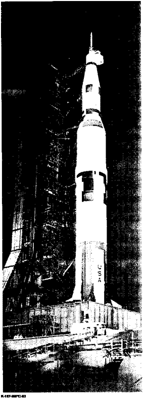
Test Vehicle… The first assembled Apollo Saturn V vehicle

approaches the launch pad at Kennedy Space Center. It was used to verify launch facilities, train launch crews, and develop test and checkout procedures at KSC. It was roiled out on

May 25, 1966.

million-pound-thrust vehicle booster. A number of available rocket engines were to be clustered and tested by a full-scale static firing by the end of 1959.

The program objectives were expanded by ARPA in October of 1958 to include a multi-stage carrier vehicle capable of performing advanced space mis­sions. Concurrent with the development of a multi­stage vehicle, static test facilities at Redstone Arsenal and launch complex facilities at Cape Canaveral—now Cape Kennedy—were being con­structed.

The proposed large vehicle project was officially renamed Saturn on Feb. 3, 1959, by ARPA memo­randum. The space agency assumed technical di­rection of the Saturn project in Sate 1959. The pro­ject was transferred officially on Mar. 16. I960, and the Army development group at Huntsville was transferred to NASA and became the nucleus of the new Marshall Space Flight Center. The first static­firing of a Saturn I booster was conducted April 29, 1960.

EARLIER SATURNS

1-3


SATURN V NEWS REFERENCE

The NASA Saturn Vehicle Evaluation Committee (Silverstein Committee) on Dec. 15, 1959, recom­mended a long-range development program for a Saturn vehicle with upper stage engines burning liquid hydrogen and liquid oxygen. The initial ve­hicle, identified as Saturn C-l and now as Saturn I, was to be a stepping stone to a larger vehicle. A building-block concept was proposed that would yield a variety of Saturn configurations, each using previously proven developments as far as possible.

Early in I960 the Satum program was given the highest national priority, and a 10-vehicle research and development program was approved.

The two-stage Saturn I vehicle with the Apollo spacecraft was about 188 feet tall and weighed some

1,125,0 pounds at liftoff.

While plans for the lunar mission were progressing, the Saturn I project made history. On Oct. 27, 1961, the first Saturn I booster was flight tested success­fully from Cape Kennedy. The first flight booster with dummy upper stages was called SA-1. This vehicle was followed by successful flights of SA-2 on April 25, 1962, SA-3 on Nov. 16, 1962, and SA-4 on Mar. 28, 1963.

The SA-5 vehicle, combining the first stage (S-l) with the second stage (S-IV), was successfully launch­ed on Jan. 29, 1964, with both stages functioning

image9

1-4

perfectly to place a 37,700-pound payload into earth orbit. SA-6, launched on May 28, 1964, and SA-7, launched on Sept. 18,1964, each placed “unmanned” boilerplate configurations of Apollo spacecraft into earth orbit.

SA-9, launched on Feb. 19, 1965, was the first Saturn I vehicle to launch a Pegasus meteoroid tech­nology satellite into earth orbit.

The SA-8 and SA-10 Satum I vehicles were success­fully launched on May 25, 1965, and July 30, 1965, respectively, also placing a Pegasus satellite into earth orbit to complete the test and launch pro­gram with an unprecedented 100 per cent record of success.

SEPARATION SYSTEM

A redundant initiation system actuates the separa­tion of the first stage from the second stage. A command signal for arming and another for firing the initiation systems are programmed by the in­strument unit computer.

After LOX depletion, the computer signals operate relays in the switch selector and sequence and con­trol distributor to control the exploding bridgewire firing units. When armed, the firing units store a high voltage electrical charge. When fired, the electrical charge actuates the ordnance.

Two firing units are installed on the first stage for the eight retrorockets, and two are installed on the second stage for the separation ordnance.

Range Safety System

The function of the range safety system is to provide ground command with the capability of flight termi­nation by shutting off the engines, blowing open the stage propellant tanks, and dispersing the fuel in event of a flight malfunction.

Подпись: 2-13

The system is redundant, consisting of two identical, independent systems, each made up of electronic and ordnance subsystems.

SATURN V NEWS

Flight termination by way of the range safety sys­tem goes into effect upon receipt of the proper radio frequency commands from the ground. A frequency-modulated RF signal transmitted from the ground range safety transmitter is received by the antennas and transmitted by way of a hybrid ring to the range safety command receiver. There, the signal is conditioned, demodulated, and decoded.

image50

Range Safety System

The resulting signal simultaneously causes arming of the exploding bridgewire firing unit and shut­down of the stage engines. A second command sig­nal transmitted by the ground range safety trans­mitter ignites the explosive train (detonating fuses and shaped charges) to blow open the stage pro­pellant tanks.

Control Pressure System

The control pressure system supplies pressurized gaseous nitrogen for the pneumatic actuation of propellant system valves and purging of various F-l engine systems.

The complete integrated system is made up of an onboard control pressure system, a ground control

2-14

REFERENCE

pressure system, and an onboard purge pressure system. The object in each system is to deliver an actuating or purge medium to an interfacing stage system.