Category Facing the Heat Barrier: a History of Hypersonics

The Х-T 5

Across almost half a century, the X-15 program stands out to this day not only for its achievements but for its audacity. At a time when the speed record stood right at Mach 2, the creators of the X-15 aimed for Mach 7—and nearly did it.[1] More­over, the accomplishments of the X-15 contrast with the history of an X-planes program that saw the X-1A and X-2 fall out of the sky due to flight instabilities, and in which the X-3 fell short in speed because it was underpowered.1

The X-15 is all the more remarkable because its only significant source of aero­dynamic data was Becker’s 11-inch hypersonic wind tunnel. Based on that instru­ment alone, the Air Force and NACA set out to challenge the potential difficulties of hypersonic piloted flight. They succeeded, with this aircraft setting speed and altitude marks that were not surpassed until the advent of the space shuttle.

It is true that these agencies worked at a time of rapid advance, when perfor­mance was leaping forward at rates never approached either before or since. Yet there was more to this craft than a can-do spirit. Its designers faced specific technical issues and overcame them well before the first metal was cut.

The X-3 had failed because it proved infeasible to fit it with the powerful tur­bojet engines that it needed. The X-15 was conceived from the start as relying on rocket power, which gave it a very ample reserve.

Flight instability was already recognized as a serious concern. Using Becker’s hypersonic tunnel, the aerodynamicist Charles McLellan showed that the effective­ness of tail surfaces could be greatly increased by designing them with wedge-shaped profiles.2

The X-15 was built particularly to study problems of heating in high-speed flight, and there was the question of whether it might overheat when re-entering the atmosphere following a climb to altitude. Calculations showed that the heating would remain within acceptable bounds if the airplane re-entered with its nose high. This would present its broad underbelly to the oncoming airflow. Here was a new application of the Allen-Eggers blunt-body principle, for an airplane with its nose up effectively became blunt.

The planes designers also benefited from a stroke of serendipity. Like any air­plane, the X-15 was to reduce its weight by using stressed-skin construction; its outer skin was to share structural loads with internal bracing. Knowing the stresses this craft would encounter, the designers produced straightforward calculations to give the requisite skin gauges. A separate set of calculations gave the skin thicknesses that were required for the craft to absorb its heat of re-entry without weakening. The two sets of skin gauges were nearly the same! This meant that the skin could do double duty, bearing stress while absorbing heat. It would not have to thicken excessively, thus adding weight, to cope with the heat.

Yet for all the ingenuity that went into this preliminary design, NACA was a very small tail on a very large dog in those days, and the dog was the Air Force. NACA alone lacked the clout to build anything, which is why one sees military insignia on photos of the X-planes of that era. Fortuitously, two new inventions—the twin – spool and the variable-stator turbojet—were bringing the Air Force face to face with a new era in flight speed. Ramjet engines also were in development, promising still higher speed. The X-15 thus stood to provide flight-test data of the highest impor­tance—and the Air Force grabbed the concept and turned it into reality.

Preludes: Asset and Lifting Bodies

At the end of the 1950s, ablatives stood out both for the ICBM and for return from space. Insulated hot structures, as on Dyna-Soar, promised reusability and

lighter weight but were less developed.

Preludes: Asset and Lifting BodiesAs early as August 1959, the Flight Dynamics Laboratory at Wright-Patter – son Air Force Base launched an in-house study of a small recoverable boost-glide vehicle that was to test hot structures during re-entry. From the outset there was strong interest in problems of aero­dynamic flutter. This was reflected in the concept name: ASSET or Aerother – modynamic/elastic Structural Systems Environmental Tests.

ASSET won approval as a program

late in January 1961. In April of that

year the firm of McDonnell Aircraft,

which was already building Mercury

capsules, won a contract to develop the

ASSET flight vehicles. Initial thought

had called for use of the solid-fuel Scout

as the booster. Soon, however, it became. . ,

АЬЬЫ, showing peak temperatures, clear that the program could use the (u. S. Air Force)

Thor for greater power. The Air Force

had deployed these missiles in England. When they came home, during 1963, they became available for use as launch vehicles.

ASSET took shape as a flat-bottomed wing-body craft that used the low-wing configuration recommended by NASA-Langley. It had a length of 59 inches and a span of 55 inches. Its bill of materials closely resembled that of Dyna-Soar, for it used TZM to withstand 3,000°F on the forward lower heat shield, graphite for similar temperatures on the leading edges, and zirconia rods for the nose cap, which was rated at 4,000°F. But ASSET avoided the use of Rene 4l, with cobalt and columbium alloys being employed instead.1

ASSET was built in two varieties: the Aerothermodynamic Structural Vehicle (ASV), weighing 1,130 pounds, and the Aerothermodynamic Elastic Vehicle (AEV), at 1,225 pounds. The AEVs were to study panel flutter along with the behavior of a trailing-edge flap, which represented an aerodynamic control surface in hypersonic flight. These vehicles did not demand the highest possible flight speeds and hence flew with single-stage Thors as the boosters. But the ASVs were built to study mate­rials and structures in the re-entry environment, while taking data on temperatures, pressures, and heat fluxes. Such missions demanded higher speeds. These boost – glide craft therefore used the two-stage Thor-Delta launch vehicle, which resembled
the Thor-Able that had conducted nose-cone tests at intercontinental range as early as 1958.2

The program conducted six flights, which had the following planned values of range and of altitude and velocity at release:

Asset Flight Tests

Date

Vehicle

Booster

Velocity,

feet/second

Altitude,

feet

Range,

nautical miles

18 September 1963

ASV-1

Thor

16,000

205,000

987

24 March 1964

ASV-2

Thor-Delta

18,000

195,000

1800

22 July 1964

ASV-3

Thor-Delta

19,500

225,000

1830

27 October 1964

AEV-1

Thor

13,000

168,000

830

8 December 1964

AEV-2

Thor

13,000

187,000

620

23 February 1965

ASV-4

Thor-Delta

19,500

206,000

2300

Source: Hallion, Hypersonic, pp. 505, 510-519.

Several of these craft were to be recovered. Following standard practice, their launches were scheduled for the early morning, to give downrange recovery crews the maximum hours of daylight. This did not help ASV-1, the first flight in the program, which sank into the sea. Still, it flew successfully and returned good data. In addition, this flight set a milestone. In the words of historian Richard Hallion, “for the first time in aerospace history, a lifting reentry spacecraft had successfully returned from space.”3

ASV-2 followed, using the two-stage Thor-Delta, but it failed when the second stage did not ignite. The next one carried ASV-3, with this mission scoring a double achievement. It not only made a good flight downrange but was successfully recov­ered. It carried a liquid-cooled double-wall test panel from Bell Aircraft, along with a molybdenum heat-shield panel from Boeing, home of Dyna-Soar. ASV-3 also had a new nose cap. The standard ASSET type used zirconia dowels, 1.5 inches long by 0.5 inch in diameter, that were bonded together with a zirconia cement. The new cap, from International Harvester, had a tungsten base covered with thorium oxide and was reinforced with tungsten.

A company advertisement stated that it withstood re-entry so well that it “could have been used again,” and this was true for the craft as a whole. Hallion writes that “overall, it was in excellent condition. Water damage…caused some problems, but not so serious that McDonnell could not have refurbished and reflown the vehicle.” The Boeing and Bell panels came through re-entry without damage, and the importance of physical recovery was emphasized when columbium aft leading edges showed significant deterioration. They were redesigned, with the new versions going into subsequent ASV and AEV spacecraft.4

The next two flights were AEVs, each of which carried a flutter test panel and a test flap. AEV-1 returned only one high-Mach data point, at Mach 11.88, but this sufficed to indicate that its panel was probably too stiff to undergo flutter. Engi­neers made it thinner and flew a new one on AEV-2, where it returned good data until it failed at Mach 10. The flap experiment also showed value. It had an elec­tric motor that deflected it into the airstream, with potentiometers measuring the force required to move it, and it enabled aerodynamicists to critique their theories. Thus, one treatment gave pressures that were in good agreement with observations, whereas another did not.

ASV-4, the final flight, returned “the highest quality data of the ASSET pro­gram,” according to the flight test report. The peak speed of 19,400 feet per second, Mach 18.4, was the highest in the series and was well above the design speed of

18,0 feet per second. The long hypersonic glide covered 2,300 nautical miles and prolonged the data return, which presented pressures at 29 locations on the vehicle and temperatures at 39. An onboard system transferred mercury ballast to trim the angle of attack, increasing L/D from its average of 1.2 to 1.4 and extending the trajectory. The only important problem came when the recovery parachute failed to deploy properly and ripped away, dooming ASV-4 to follow ASV-1 into the depths of the Atlantic.5

On the whole, ASSET nevertheless scored a host of successes. It showed that insulated hot structures could be built and flown without producing unpleasant surprises, at speeds up to three-fourths of orbital velocity. It dealt with such practical issues of design as fabrication, fasteners, and coatings. In hypersonic aerodynamics, ASSET contributed to understanding of flutter and of the use of movable con­trol surfaces. The program also developed and successfully used a reaction control system built for a lifting re-entry vehicle. Only one flight vehicle was recovered in four attempts, but it complemented the returned data by permitting a close look at a hot structure that had survived its trial by fire.

A separate prelude to the space shuttle took form during the 1960s as NASA and the Air Force pursued a burgeoning interest in lifting bodies. The initial con­cept represented one more legacy of the blunt-body principle of H. Julian Allen and Alfred Eggers at NACA’s Ames Aeronautical Laboratory. After developing this principle, they considered that a re-entering body, while remaining blunt to reduce its heat load, might produce lift and thus gain the ability to maneuver at hypersonic speeds. An early configuration, the M-l of 1957, featured a blunt-nosed cone with a flattened top. It showed some capacity for hypersonic maneuver but could not glide subsonically or land on a runway. A new shape, the M-2, appeared as a slender half-cone with its flat side up. Its hypersonic L/D of 1.4 was nearly triple that of the M-l. Fitted with two large vertical fins for stability, it emerged as a basic configura­tion that was suitable for further research.6

Dale Reed, an engineer at NASA’s Flight Research Center, developed a strong interest in the bathtub-like shape of the M-2. He was a sailplane enthusiast and a builder of radio-controlled model aircraft. With support from the local community of airplane model builders, he proceeded to craft the M-2 as a piloted glider. Desig­nating it as the M2-F1, he built it of plywood over a tubular steel frame. Completed early in 1963, it was 20 feet long and 13 feet across.

It needed a vehicle that could tow it into the air for initial tests. However, it produced too much drag for NASA’s usual vans and trucks, and Reed needed a tow car with more power. He and his friends bought a stripped-down Pontiac with a big engine and a four-barrel carburetor that reached speeds of 110 miles per hour. They took it to a funny-car shop in Long Beach for modification. Like any other flightline vehicle, it was painted yellow with “National Aeronautics and Space Administra­tion” on its side. Early tow tests showed enough success to allow the project to use a C-47, called the Cooney Bird, for true aerial flights. During these tests the Cooney Bird towed the M2-F1 above 10,000 feet and then set it loose to glide to an Edwards AFB lakebed. Beginning in August 1963, the test pilot Milt Thompson did this repeatedly. Reed thus showed that although the basic M-2 shape had been crafted for hypersonic re-entry, it could glide to a safe landing.

As he pursued this work, he won support from Paul Bikle, the director of NASA Flight Research Center. As early as April 1963, Bikle alerted NASA Headquarters that “the lifting-body concept looks even better to us as we get more into it.” The success of the M2-F1 sparked interest within the Air Force as well. Some of its offi­cials, along with their NASA counterparts, went on to pursue lifting-body programs that called for more than plywood and funny cars. An initial effort went beyond the M2-F1 by broadening the range of lifting-body shapes while working to develop satisfactory landing qualities.7

NASA contracted with the firm of Northrop to build two such aircraft: the M2- F2 and HL-10. The M2-F2 amounted to an M2-F1 built to NASA standards; the HL-10 drew on an alternate lifting-body design by Eugene Love of NASA-Langley. This meant that both Langley and Ames now had a project. The Air Force effort, the X-24A, went to the Martin Company. It used a design of Frederick Raymes at the Aerospace Corporation that resembled a teardrop fitted with two large fins.

All three flew initially as gliders, with a B-52 rather than a C-47 as the mother ship. The lifting bodies mounted small rocket engines for acceleration to supersonic

speeds, thereby enabling tests of stability and handling qualities in transonic flight. The HL-10 set records for lifting bodies by making safe approaches and landings at Edwards from speeds up to Mach 1.86 and altitudes of 90,000 feet.8

Acceptable handling qualities were not easy to achieve. Under the best of cir­cumstances, a lifting body flew like a brick at low speeds. Lowering the landing gear made the problem worse by adding drag, and test pilots delayed this deployment as long as possible. In May 1967 the pilot Bruce Peterson, flying the M2-F2, failed to get his gear down in time. The aircraft hit the lakebed at more than 250 mph, rolled over six times, and then came to rest on its back minus its cockpit canopy, main landing gear, and right vertical fin. Peterson, who might have died in the crash, got away with a skull fracture, a mangled face, and the loss of an eye. While surgeons reconstructed his face and returned him to active duty, the M2-F2 underwent sur­gery as well. Back at Northrop, engineers installed a center fin and a roll-control system that used reaction jets, while redistributing the internal weights. Gerauld Gentry, an Air Force test pilot, said that these changes turned “something I really did not enjoy flying at all into something that was quite pleasant to fly.”9

The manned lifting-body program sought to turn these hypersonic shapes into aircraft that could land on runways, but the Air Force was not about to overlook the need for tests of their hypersonic performance during re-entry. The program that addressed this issue took shape with the name PRIME, Precision Recovery Includ­ing Maneuvering Entry. Martin Marietta, builder of the X-24A, also developed the PRIME flight vehicle, the SV-5D that later was referred to as the X-23- Although it was only seven feet in length, it faithfully duplicated the shape of the X-24A, even including a small bubble-like protrusion near the front that represented the cockpit canopy.

PRIME complemented ASSET, with both programs conducting flight tests of boost-glide vehicles. However, while ASSET pushed the state of the art in materials and hot structures, PRIME used ablative thermal protection for a more straightfor­ward design and emphasized flight performance. Accelerated to near-orbital veloci­ties by Atlas launch vehicles, the PRIME missions called for boost-glide flight from Vandenberg AFB to locations in the western Pacific near Kwajalein Atoll. The SV – 5D had higher L/D than Gemini or Apollo, and as with those NASA programs, it was to demonstrate precision re-entry. The plans called for crossrange, with the vehicle flying up to 710 nautical miles to the side of a ballistic trajectory and then arriving within 10 miles of its recovery point.10

The X-24A was built of aluminum. The SV-5D used this material as well, for both the skin and primary structure. It mounted both aerodynamic and reaction controls, with the former taking shape as right and left body-mounted flaps set well aft. Used together, they controlled pitch; used individually, they produced yaw and roll. These flaps were beryllium plates that provided thermal heat sink. The fins were of steel honeycomb with surfaces of beryllium sheet.

Preludes: Asset and Lifting Bodies

Lifting bodies. Left to right: the X-24A, the M2-F3 which was modified from the M2-F2, and the HL-10. (NASA)


Preludes: Asset and Lifting Bodies

Landing a lifting body. The wingless X-24B required a particularly high angle of attack. (NASA)


Preludes: Asset and Lifting BodiesPreludes: Asset and Lifting Bodies

Martin SV-5D, which became the X-23. Mission of the SV-5D. (U. S. Air Force)

Подпись: ЙЗ rfp да Mt ,'K1 fW JW ^ jptf О? да

(U. S. Air Force)

Trajectory of the SV-5D, showing crossrange. (U. S. Air Force)

Most of the vehicle surface obtained thermal protection from ESA 3560 HF, a flexible ablative blanket of phenolic fiberglass honeycomb that used a silicone elas­tomer as the filler, with fibers of nylon and silica holding the ablative char in place during re-entry. ESA 5500 HE a high-density form of this ablator, gave added pro­tection in hotter areas. The nose cap and the beryllium flaps used a different mate­rial: a carbon-phenolic composite. At the nose, its thickness reached 3-5 inches.11

The PRIME program made three flights, which took place between December 1966 and April 1967. All returned data successfully, with the third flight vehicle also being recovered. The first mission reached 25,300 feet per second and flew 4,300 miles downrange, missing its target by only 900 feet. The vehicle executed pitch maneuvers but made no attempt at crossrange. The next two flights indeed achieved crossrange, of 500 and 800 nautical miles, and the precision again was impressive. Flight 2 missed its aim point by less than two miles. Flight 3 missed by more than four miles, but this still was within the allowed limit. Moreover, the terminal guid­ance radar had been inoperative, which probably contributed to the lack of absolute accuracy.12

By demonstrating both crossrange and high accuracy during maneuvering entry, PRIME broadened the range of hypersonic aircraft configurations and completed a line of development that dated to 1953- In December of that year the test pilot Chuck Yeager had nearly been killed when his X-1A fell out of the sky at Mach 2.44 because it lacked tail surfaces that could produce aerodynamic stability. The X-l 5 was to fly to Mach 6, and Charles McLellan of NACA-Langley showed that it could use vertical fins of reasonable size if they were wedge-shaped in cross section. Meanwhile, Allen and Eggers were introducing their blunt-body principle. This led to missile nose cones with rounded tips, designed both as cones and as blunted cylinders that had stabilizing afterbodies in the shape of conic frustums.

For manned flight, Langleys Maxime Faget introduced the general shape of a cone with its base forward, protected by an ablative heat shield. Langleys John Becker entered the realm of winged re-entry configurations with his low-wing flat-bottom shapes that showed advantage over the high-wing flat-top concepts of NACA-Ames. The advent of the lifting body then raised the prospect of a struc­turally efficient shape that lacked wings, demanded thermal protection and added weight, and yet could land on a runway. Faget’s designs had found application in Mercury, Gemini, and Apollo, while Becker’s winged vehicle had provided a basis for Dyna-Soar. As NASA looked to the future, both winged designs and lifting bodies were in the forefront.13

Hypersonics and the Aviation Frontier

Aviation has grown through reliance upon engines, and three types have been important: the piston motor, turbojet, and rocket. Hypersonic technologies have made their largest contributions, not by adding the scramjet to this list, but by enhancing the value and usefulness of rockets. This happened when these technolo­gies solved the re-entry problem.

This problem addressed critical issues of the national interest, for it was essential to the success of Corona and of the return of film-carrying capsules from orbit. It also was a vital aspect of the development of strategic missiles. Still, if such weapons had proven to be technically infeasible, the superpowers would have fallen back on their long-range bombers. No such backup was available within the Corona program. During the mid-1960s the Lunar Orbiter Program used a high-resolution system for scanning photographic film, with the data being returned using telem­etry.88 But this arrangement had a rather slow data rate and was unsuitable for the demands of strategic reconnaissance.

Success in re-entry also undergirded the piloted space program. In 40 years of effort, this program has failed to find a role in the mainstream of technical activity akin to the importance of automated satellites in telecommunications. Still, piloted flight brought the unforgettable achievements of Apollo, which grow warmer in memory as the decades pass.

In a related area, the advent of thermal-protection methods led to the develop­ment of aircraft that burst all bounds on speed and altitude. These took form as the X-15 and the space shuttle. On the whole, though, this work has led to disappoint­ment. The Air Force had anticipated that airbreathing counterparts of the X-15, powered perhaps by ramjets, would come along in the relatively near future. This did not happen; the X-15 remains sui generis, a thing unto itself. In turn, the shuttle failed to compete effectively with expendable launch vehicles.

This conclusion remains valid in the wake of the highly publicized flights of SpaceShipOne, built by the independent inventor Burt Rutan. Rutan showed an uncanny talent for innovation in 1986, when his Voyager aircraft, piloted by his brother Dick and by Dicks former girlfriend Jeana Yeager, circled the world on a single load of fuel. This achievement had not even been imagined, for no science – fiction writer had envisioned such a nonstop flight around the world. What made it possible was the use of composites in construction. Indeed, Voyager was built at

Rutan’s firm of Scaled Composites.89 Such lightweight materials also found use in the construction of SpaceShipOne, which was assembled within that plant.

SpaceShipOne brought the prospect of routine commercial flights having the performance of the X-15. Built entirely as a privately funded venture, it used a simple rocket engine that burned rubber, with nitrous oxide as the oxidizer, and reached altitudes as high as 70 miles. A movable set of wings and tail booms, rotat­ing upward, provided stability in attitude during re-entry and kept the crafts nose pointing upward as well. The craft then glided to a landing.

There was no commercial follow-on to Voyager, but today there is serious inter­est in building commercial versions of SpaceShipOne that will take tourists on brief hops into space—and enable them to win astronauts’ wings in the process. Rich­ard Branson, founder of Virgin Airways, is currently sponsoring a new enterprise, Virgin Galactic, that aims to do just that. He has formed a partnership with Scaled, has sold more than 100 tickets at $200,000 each, and hopes for his first flight late in 2008.

And yet__ The top speed of SpaceShipOne was only 2,200 miles per hour, or

Mach 3-3. Rutans vehicle thus stands today as a brilliant exercise in rocketry and the design of reusable piloted spacecraft. But it is too slow to qualify as a project in hypersonics.90

Is that it, then? Following more than half a century of effort, does the re-entry problem stand as the single unambiguous contribution of hypersonics? Air Force historian Richard Hallion has written of a “hypersonic revolution,” but from this perspective, one may regard hypersonics less as an extension of aeronautics than as a branch of materials science, akin to metallurgy. Specialists in that field introduced superalloys that extended the temperature limits of jet engines, thereby enhanc­ing their range and fuel economy. Similarly, the hypersonics community developed lightweight thermal-protection systems that have found use even in exploring the planet Jupiter. Yet one does not speak of a “superalloy revolution,” and hypersonics has had similarly limited application.

There remains the issue of the continuing effort to develop the scramjet. This work has gone forward as part of an ongoing hope that better methods might be devised for ascent to orbit, corresponding perhaps to the jet airliners that drove their piston-driven counterparts to the boneyard. Access to space holds undeniable importance, and one may speak without challenge of a “satellite revolution” when we consider the vital role of such craft in a host of areas: weather forecasting, naviga­tion, tactical warfare, reconnaissance, as well as telecommunications. Yet low-cost access remains out of reach and hence continues to justify work on advanced tech­nologies, including scramjets.

Still, despite 40 years of effort, the scramjet continues to stand at two removes from importance. The first goal is simply to make it work, by demonstrating flight to orbit in a vehicle that uses such engines for propulsion. The X-30 was to fly in

this fashion, although present-day thinking leans more toward using it merely in an airbreathing first stage. But at least within the next decade the most that anyone hopes for is to accelerate a small test vehicle of the X-43 class.91

Yet even if a large launch vehicle indeed should fly using scramjets, it then will face a subsequent test, for it will have to win success in the face of competition from existing launchers. The history of aerospace shows several types of craft that indeed flew well but that failed in the market. The classic example was the dirigible, which was abandoned because it could not be made safe.92

The world still remembers the Hindenburg, but the problems ran deeper than the use of hydrogen. Even with nonflammable helium, such airships proved to be structurally weak. The U. S. Navy built three large ones—the Shenandoah, Akron, and Macon—and quickly lost them all in storms and severe weather. Nor has this problem been solved. Dirigibles might be attractive today as aerial cruise ships, offering unparalleled views of Caribbean islands, but the safety problem persists.

More recently the Concorde supersonic airliner flew with great style and panache but faltered due to its high costs. The Saturn V Moon rocket proved to be too large to justify continued production; it lacked payloads that demanded its heft. Piloted space flight raises its own questions. It too is very costly, and in the light of experi­ence with the shuttle, perhaps it too cannot be made completely safe.

Yet though scramjets face obstacles both in technology and in the market, they will continue to tantalize. Hallion writes that faith in a future for hypersonics “is akin to belief in the Second Coming: one knows and trusts that it will occur, but one can’t be certain when.” Scramjet advocates will continue to echo the defiant words of Eugen Sanger: “Nevertheless, my silver birds will fly!”93

[1]Official flight records are certified by the Federation Aeronautique Internationale. The cited accomplishments lacked this distinction, but they nevertheless represented genuine achievements.

Origins of the x-15

Experimental aircraft flourished during the postwar years, but it was hard for them to keep pace with the best jet fighters. The X-l, for instance, was the first piloted aircraft to break the sound barrier. But only six months later, in April 1948, the test pilot George Welch did this in a fighter plane, the XP-86.3 The layout of the XP-86 was more advanced, for it used a swept wing whereas the X-l used a simple straight wing. Moreover, while the X-l was a highly specialized research airplane, the XP-86 was a prototype of an operational fighter.

Much the same happened at Mach 2. The test pilot Scott Crossfield was the first to reach this mark, flying the experimental Douglas Skyrocket in November 1953.4 Just then, Alexander Kartveli of Republic Aviation was well along in crafting the XF-105. The Air Force had ordered 37 of them in March 1953- It first flew in December 1955; in June 1956 an F-105 reached Mach 2.15. It too was an opera­tional fighter, in contrast to the Skyrocket of two and a half years earlier.

Ramjet-powered craft were to do even better. Navaho was to fly near Mach 3- An even more far-reaching prospect was in view at that same Republic Aviation, where Kartveli was working on the XF-103. It was to fly at Mach 3-7 with its own ramjet, nearly 2,500 miles per hour (mph), with a sustained ceiling of 75,000 feet.5

Yet it was already clear that such aircraft were to go forward in their programs without benefit of research aircraft that could lay groundwork. The Bell X-2 was in development as a rocket plane designed to reach Mach 3, but although first thoughts of it dated to 1945, the program encountered serious delays. The airplane did not so much as fly past Mach 1 until 1956.6

Hence in 1951 and 1952, it already was too late to initiate a new program aimed at building an X-plane that could provide timely support for the Navaho and XF – 103- The X-10 supported Navaho from 1954 to 1957, but it used turbojets rather than ramjets and flew at Mach 2.There was no quick and easy way to build aircraft capable of Mach 3, let alone Mach 4; the lagging X-2 was the only airplane that might do this, however belatedly Yet it was already appropriate to look beyond the coming Mach 3 generation and to envision putative successors.

Maxwell Hunter, at Douglas Aircraft, argued that with fighter aircraft on their way to Mach 3, antiaircraft missiles would have to fly at Mach 5 to Mach 10/ In addition, Walter Dornberger, the wartime head of Germany’s rocket program, now was at Bell Aircraft. He was directing studies of Bomi, Bomber Missile, a two – stage fully reusable rocket-powered bomber concept that was to reach 8,450 mph, or Mach 12.8 At Convair, studies of intercontinental missiles included boost-glide concepts with much higher speeds.9 William Dorrance, a company aerodynamicist, had not been free to disclose the classified Atlas concept to NACA but nevertheless declared that data at speeds up to Mach 20 were urgently needed.10 In addition, the Rand Corporation had already published reports that envisioned spacecraft in orbit. The documents proposed that such satellites could serve for weather observation and for military reconnaissance.11

At Bell Aircraft, Robert Woods, a co-founder of the company, took a strong interest in Dornberger’s ideas. Woods had designed the X-l, the X-1A that reached Mach 2.4, and the X-2. He also was a member ofNACAs influential Committee on Aerodynamics. At a meeting of this committee in October 1951, he recommended a feasibility study of a “V-2 research airplane, the objective of which would be to obtain data at extreme altitudes and speeds and to explore the problems of re-entry into the atmosphere.”12 He reiterated this recommendation in a letter to the com­mittee in January 1952. Later that month, he received a memo from Dornberger that outlined an “ionospheric research plane,” capable of reaching altitudes of “more than 75 miles.”13

NACA Headquarters sent copies of these documents to its field centers. This brought responses during May, as several investigators suggested means to enhance the performance of the X-2. The proposals included a rocket-powered carrier air­craft with which this research airplane was to attain “Mach numbers up to almost 10 and an altitude of about 1,000,000 feet,”14 which the X-2 had certainly never been meant to attain. A slightly more practical concept called for flight to 300,000 feet.15 These thoughts were out in the wild blue, but they showed that people at least were ready to think about hypersonic flight.

Accordingly, at a meeting in June 1952, the Committee on Aerodynamics adopted a resolution largely in a form written by another of its members, the Air Force science advisor Albert Lombard:

WHEREAS, The upper stratosphere is the important new flight region for military aircraft in the next decade and certain guided missiles are already under development to fly in the lower portions of this region, and WHEREAS, Flight in the ionosphere and in satellite orbits in outer space has long-term attractiveness to military operations—

RESOLVED, That the NACA Committee on Aerodynamics recommends that (1) the NACA increase its program dealing with problems of unmanned and manned flight in the upper stratosphere at altitudes between 12 and 50 miles, and at Mach numbers between 4 and 10, and (2) the NACA devote a modest effort to problems associated with unmanned and manned flights at altitudes from 50 miles to infinity and at speeds from Mach number 10 to the velocity of escape from the Earth’s gravity.

Three weeks later, in mid-July, the NACA Executive Committee adopted essen­tially the same resolution, thus giving it the force of policy.16

Floyd Thompson, associate director of NACA-Langley, responded by setting up a three-man study team. Their report came out a year later. It showed strong fascina­tion with boost-glide flight, going so far as to propose a commercial aircraft based on a boost-glide Atlas concept that was to match the standard fares of current airliners. On the more immediate matter of a high-speed research airplane, this group took the concept of a boosted X-2 as a point of departure, suggesting that such a vehicle could reach Mach 3-7. Like the million-foot X-2 and the 300,000-foot X-2, this lay beyond its thermal limits. Still, this study pointed clearly toward an uprated X-2 as the next step.17

The Air Force weighed in with its views in October 1953. A report from the Aircraft Panel of its Scientific Advisory Board (SAB) discussed the need for a new research airplane of very high performance. The panelists stated that “the time was ripe” for such a venture and that its feasibility “should be looked into.”18 With this plus the report of the Langley group, the question of such a research plane went on the agenda of the next meeting of NACA’s Interlaboratory Research Airplane Panel. It took place at NACA Headquarters in Washington in February 1954.

It lasted two days. Most discussions centered on current programs, but the issue of a new research plane indeed came up. The participants rejected the concept of an uprated X-2, declaring that it would be too small for use in high-speed studies. They concluded instead “that provision of an entirely new research airplane is desir­able.”19

This decision led quickly to a new round of feasibility studies at each of the four NACA centers: Langley, Ames, Lewis, and the High-Speed Flight Station. The study conducted at Langley was particularly detailed and furnished much of the basis for the eventual design of the X-15- Becker directed the work, taking respon­sibility for trajectories and aerodynamic heating. Maxime Faget addressed issues of propulsion. Three other specialists covered the topics of structures and materials, piloting, configuration, stability, and control.20

A performance analysis defined a loaded weight of 30,000 pounds. Heavier weights did not increase the peak speed by much, whereas smaller concepts showed a marked falloff in this speed. Trajectory studies then showed that this vehicle could reach a range of speeds, from Mach 5 when taking off from the ground to Mach 10 if launched atop a rocket-powered first stage. If dropped from a B-52 carrier, it would attain Mach 6.3.21

Concurrently with this work, prompted by a statement written by Langleys Robert Gilruth, the Air Force’s Aircraft Panel recommended initiation of a research airplane that would reach Mach 5 to 7, along with altitudes of several hundred thou­sand feet. Beckers group selected a goal of Mach 7, noting that this would permit investigation of “extremely wide ranges of operating and heating conditions.” By contrast, a Mach 10 vehicle “would require a much greater expenditure of time and effort” and yet “would add little in the fields of stability, control, piloting problems, and structural heating.”22

A survey of temperature-resistant superalloys brought selection of Inconel X for the primary aircraft structure. This was a proprietary alloy from the firm of Inter­national Nickel, comprising 72.5 percent nickel, 15 percent chromium, 1 percent columbium, and iron as most of the balance. Its principal constituents all counted among the most critical materials used in aircraft construction, being employed in small quantities for turbine blades in jet engines. But Inconel X was unmatched in temperature resistance, holding most of its strength and stiffness at temperatures as high as 1200°F.23

Could a Mach 7 vehicle re-enter the atmosphere without exceeding this tem­perature limit? Becker’s designers initially considered that during reentry, the air­plane should point its nose in the direction of flight. This proved impossible; in Becker’s words, “the dynamic pressures quickly exceeded by large margins the limit of 1,000 pounds per square foot set by structural considerations, and the heating loads became disastrous.”

Becker tried to alleviate these problems by using lift during re-entry. According to his calculations, he obtained more lift by raising the nose—and the problem became far more manageable. He saw that the solution lay in having the plane enter the atmosphere with its nose high, presenting its flat undersurface to the air. It then would lose speed in the upper atmosphere, easing both the overheating and the aerodynamic pressure. The Allen-Eggers paper had been in print for nearly a year, and in Becker’s words, “it became obvious to us that what we were seeing here was a new manifestation of H. J. Allen’s ‘blunt-body’ principle. As we increased the angle of attack, our configuration in effect became more ‘blunt.’” Allen and Eggers had

Origins of the x-15

X-15 skin gauges and design temperatures. Generally, the heaviest gauges were required to meet the most severe temperatures. (NASA)

developed their principle for missile nose cones, but it now proved equally useful when applied to a hypersonic airplane.24

The use of this principle now placed a structural design concept within reach. To address this topic, Norris Dow, the structural analyst, considered the use of a heat-sink structure. This was to use Inconel X skin of heavy gauge to absorb the heat and spread it through this metal so as to lower its temperature. In addition, the skin was to play a structural role. Like other all-metal aircraft, the nascent X-15 was to use stressed-skin construction. This gave the skin an optimized thickness so that it could carry part of the aerodynamic loads, thus reducing the structural weight.

Dow carried through a design exercise in which he initially ignored the issue of heating, laying out a stressed-skin concept built of Inconel X with skin gauges deter­mined only by requirements of mechanical strength and stiffness. A second analysis then took note of the heating, calculating new gauges that would allow the skin to serve as a heat sink. It was clear that if those gauges were large, adding weight to the airplane, then it might be necessary to back off from the Mach 7 goal so as to reduce the input heat load, thereby reducing the required thicknesses.

When Dow made the calculations, he received a welcome surprise. He found that the weight and thickness of a heat-absorbing structure were nearly the same as those of a simple aerodynamic structure! This meant that a hypersonic airplane, designed largely from consideration of aerodynamic loads, could provide heat-sink thermal protection as a bonus. It could do this with little or no additional weight.25

This, more than anything, was the insight that made the X-15 possible. Design­ers such as Dow knew all too well that ordinary aircraft aluminum lost strength beyond Mach 2, due to aerodynamic heating. Yet if hypersonic flight was to mean anything, it meant choosing a goal such as Mach 7 and then reaching this goal through the clever use of available heat-resistant materials. In Becker’s study, the Allen-Eggers blunt-body principle reduced the re-entry heating to a level that Inco­nel X could accommodate.

The putative airplane still faced difficult issues of stability and control. Early in 1954 these topics were in the forefront, for the test pilot Chuck Yeager had nearly crashed when his X-1A fell out of the sky due to a loss of control at Mach 2.44. This problem of high-speed instability reflected the natural instability, at all Mach num­bers, of a simple wing-body vehicle that lacked tail surfaces. Such surfaces worked well at moderate speeds, like the feathers of an arrow, but lost effectiveness with increasing Mach. Yeager’s near-disaster had occurred because he had pushed just beyond a speed limit set by such considerations of stability. These considerations would be far more severe at Mach 7-26

Another Langley aerodynamicist, Charles McLellan, took up this issue by closely examining the airflow around a tail surface at high Mach. He drew on recent experi­mental results from the Langley 11-inch hypersonic tunnel, involving an airfoil with a cross section in the shape of a thin diamond. Analysis had indicated that most of the control effectiveness of this airfoil was generated by its forward wedge-shaped portion. The aft portion contributed little to its overall effectiveness because the pres­sures on that part of the surface were lower. Experimental tests had confirmed this.

McLellan now proposed to respond to the problem of hypersonic stability by using tail surfaces having airfoils that would be wedge-shaped along their entire length. In effect, such a surface would consist of a forward portion extending all the way to the rear. Subsequent tests in the 11-inch tunnel confirmed that this solution worked. Using standard thin airfoils, the new research plane would have needed tail surfaces nearly as large as the wings. The wedge shape, which saw use in the opera­tional X-15, reduced their sizes to those of conventional tails.27

The groups report, dated April 1954, contemplated flight to altitudes as great as 350,000 feet, or 66 miles. (The X-15 went to 354,200 feet in 1963-)28This was well above the sensible atmosphere, well into an altitude range where flight would be bal­listic. This meant that at that early date, Becker’s study was proposing to accomplish piloted flight into space.

Reusable Surface Insulation

As PRIME and the lifting bodies broadened the choices of hypersonic shape, work at Lockheed made similar contributions in the field of thermal protection. Ablatives were unrivaled for once-only use, but during the 1960s the hot structure continued to stand out as the preferred approach for reusable craft such as Dyna – Soar. As noted, it used an insulated primary or load-bearing structure with a skin of outer panels. These emitted heat by radiation, maintaining a temperature that was high but steady. Metal fittings supported these panels, and while the insulation could be high in quality, these fittings unavoidably leaked heat to the underlying structure. This raised difficulties in crafting this structure of aluminum or even of titanium, which had greater heat resistance. On Dyna-Soar, only Rene 41 would do.14

Ablatives avoided such heat leaks, while being sufficiently capable as insulators to permit the use of aluminum, as on the SV-5D of PRIME. In principle, a third approach combined the best features of hot structure and ablatives. It called for the use of temperature-resistant tiles, made perhaps of ceramic, that could cover the vehicle skin. Like hot-structure panels, they would radiate heat while remaining cool enough to avoid thermal damage. In addition, they were to be reusable. They also were to offer the excellent insulating properties of good ablators, preventing heat from reaching the underlying structure—which once more might be of alumi­num. This concept, known as reusable surface insulation (RSI), gave rise in time to the thermal protection of the shuttle.

RSI grew out of ongoing work with ceramics for thermal protection. Ceramics had excellent temperature resistance, light weight, and good insulating properties. But they were brittle, and they cracked rather than stretched in response to the flex­ing under load of an underlying metal primary structure. Ceramics also were sensi­tive to thermal shock, as when heated glass breaks when plunged into cold water. This thermal shock resulted from rapid temperature changes during re-entry.15

Monolithic blocks of the ceramic zirconia had been specified for the nose cap of Dyna-Soar, but a different point of departure used mats of ceramic fiber in lieu of the solid blocks. The background to the shuttles tiles lay in work with such mats that dated to the early 1960s at Lockheed Missiles and Space Company. Key people included R. M. Beasley, Ronald Banas, Douglas Izu, and Wilson Schramm. A Lock­heed patent disclosure of December I960 gave the first presentation of a reusable insulation made of ceramic fibers for use as a heat shield. Initial research dealt with casting fibrous layers from a slurry and bonding the fibers together.

Related work involved filament-wound structures that used long continuous strands. Silica fibers showed promise and led to an early success: a conical radome of 32-inch diameter built for Apollo in 1962. Designed for re-entry, it had a filament – wound external shell and a lightweight layer of internal insulation cast from short fibers of silica. The two sections were densified with a colloid of silica particles and
sintered into a composite. This resulted in a non-ablative structure of silica compos­ite, reinforced with fiber. It never flew, as design requirements changed during the development of Apollo. Even so, it introduced silica fiber into the realm of re-entry design.

Another early research effort, Lockheat, fabricated test versions of fibrous mats that had controlled porosity and microstructure. These were impregnated with organic fillers such as Plexiglas (methyl methacrylate). These composites resembled ablative materials, although the filler did not char. Instead it evaporated or volatil­ized, producing an outward flow of cool gas that protected the heat shield at high heat-transfer rates. The Lockheat studies investigated a range of fibers that included silica, alumina, and boria. Researchers constructed multilayer composite structures of filament-wound and short-fiber materials that resembled the Apollo radome. Impregnated densities were 40 to 60 pounds per cubic foot, the higher number being close to the density of water. Thicknesses of no more than an inch resulted in acceptably low back-face temperatures during simulations of re-entry.

This work with silica-fiber ceramics was well under way during 1962. Three years later a specific formulation of bonded silica fibers was ready for further develop­ment. Known as LI-1500, it was 89 percent porous and had a density of 15 pounds per cubic foot, one-fourth that of water. Its external surface was impregnated with filler to a predetermined depth, again to provide additional protection during the most severe re-entry heating. By the time this filler was depleted, the heat shield was to have entered a zone of more moderate heating, where the fibrous insulation alone could provide protection.

Initial versions of LI-1500, with impregnant, were intended for use with small space vehicles, similar to Dyna-Soar, that had high heating rates. Space shuttle con­cepts were already attracting attention—the January 1964 issue of the trade journal Astronautics & Aeronautics presents the thinking of the day—and in 1965 a Lock­heed specialist, Max Hunter, introduced an influential configuration called Star Clipper. His design called for LI-1500 as the thermal protection.

Like other shuttle concepts, Star Clipper was to fly repeatedly, but the need for

Reusable Surface Insulationan impregnant in LI-1500 compromised its reusabil­ity. In contrast to earlier entry vehicle concepts, Star Clipper was large, offering exposed surfaces that were sufficiently blunt to benefit from the Allen-Eggers prin­ciple. They had lower tem­peratures and heating rates,

Star Clipper concept. (Art by Dan Gautier)
which made it possible to dispense with the impregnant. An unfilled version of LI-1500, which was inherently reusable, now could serve.

Here was the first concept of a flight vehicle with reusable insulation, bonded to the skin, that could reradiate heat in the fashion of a hot structure. However, the matted silica by itself was white and had low thermal emissivity, making it a poor radiator of heat. This brought excessive surface temperatures that called for thick layers of the silica insulation, adding weight. To reduce the temperatures and the thickness, the silica needed a coating that could turn it black, for high emissivity. It then would radiate well and remain cooler.

The selected coating was a borosilicate glass, initially with an admixture of chro­mium oxide and later with silicon carbide, which further raised the emissivity. The glass coating and silica substrate were both silicon dioxide; this assured a match of their coefficients of thermal expansion, to prevent the coating from developing cracks under the temperature changes of re-entry. The glass coating could soften at very high temperatures to heal minor nicks or scratches. It also offered true reusabil­ity, surviving repeated cycles to 2,500°F. A flight test came in 1968, as NASA-Lang – ley investigators mounted a panel of LI-1500 to a Pacemaker re-entry test vehicle, along with several candidate ablators. This vehicle carried instruments, and it was recovered. Its trajectory reproduced the peak heating rates and temperatures of a re­entering Star Clipper. The LI-1500 test panel reached 2,300°F and did not crack, melt, or shrink. This proof-of-concept test gave further support to the concept of high-emittance reradiative tiles of coated silica for thermal protection.16

Lockheed conducted further studies at its Palo Alto Research Center. Investiga­tors cut the weight of RSI by raising its porosity from the 89 percent of LI-1500 to 93 percent. The material that resulted, LI-900, weighed only nine pounds per cubic foot, one-seventh the density of water.17 There also was much fundamental work on materials. Silica exists in three crystalline forms: quartz, cristobalite, tridymite. These not only have high coefficients of thermal expansion but also show sudden expansion or contraction with temperature due to solid-state phase changes. Cris­tobalite is particularly noteworthy; above 400°F it expands by more than 1 percent as it transforms from one phase to another. Silica fibers for RSI were to be glass, an amorphous rather than crystalline state having a very low coefficient of thermal expansion and absence of phase changes. The glassy form thus offered superb resis­tance to thermal stress and thermal shock, which would recur repeatedly during each return from orbit.18

The raw silica fiber came from Johns-Manville, which produced it from high – purity sand. At elevated temperatures it tended to undergo “devitrification,” trans­forming from a glass into a crystalline state. Then, when cooling, it passed through phase-change temperatures and the fiber suddenly shrank, producing large internal tensile stresses. Some fibers broke, giving rise to internal cracking within the RSI and degradation of its properties. These problems threatened to grow worse during subsequent cycles of re-entry heating.

To prevent devitrification, Lockheed worked to remove impurities from the raw fiber. Company specialists raised the purity of the silica to 99-9 percent while reduc­ing contaminating alkalis to as low as six parts per million. Lockheed did these things not only at the laboratory level but also in a pilot plant. This plant took the silica from raw material to finished tile, applying 140 process controls along the way. Established in 1970, the pilot plant was expanded in 1971 to attain a true manufacturing capability. Within this facility, Lockheed produced tiles of LI-1500 and LI-900 for use in extensive programs of test and evaluation. In turn, the increas­ing availability of these tiles encouraged their selection for shuttle thermal protec­tion, in lieu of a hot-structure approach.19

General Electric also became actively involved, studying types of RSI made from zirconia and from mullite, as well as from silica. The raw fibers were commercial grade, with the zirconia coming from Union Carbide and the mullite from Babcock and Wilcox. Devitrification was a problem, but whereas Lockheed had addressed it by purifying its fiber, GE took the raw silica from Johns-Manville and tried to use it with little change. The basic fiber, the Q-felt of Dyna-Soar, also had served as insulation on the X-15. It contained 19 different elements as impurities. Some were present at a few parts per million, but others—aluminum, calcium, copper, lead, magnesium, potassium, sodium—ran from 100 to 1000 parts per million. In total, up to 0.3 percent was impurity. General Electric treated this fiber with a silicone resin that served as a binder, pyrolyzing the resin and causing it to break down at high temperatures. This transformed the fiber into a composite, sheath­ing each strand with a layer of amorphous silica that had a purity of 99-98 percent and higher. This high purity resulted from that of the resin. The amorphous silica bound the fibers together while inhibiting their devitrification. General Electrics RSI had a density of 11.5 pounds per cubic foot, midway between that of LI-900 and LI-1500.20

In January 1972, President Richard Nixon gave his approval to the space shuttle program, thereby raising it to the level of a presidential initiative. Within days, NASA’s Dale Myers spoke to a lunar science conference in Houston and stated that the agency had made the basic decision to use RSI. Requests for proposal soon went out, inviting leading aerospace corporations to bid for the prime contract on the shuttle orbiter, and North American won this $2.б-billion prize in July. It specified mullite RSI for the undersurface and forward fuselage, a design feature that had been held over from the fully-reusable orbiter of the previous year.

Most of the primary structure was aluminum, but that of the nose was titanium, with insulation of zirconia lining the nose cap. The wing and fuselage upper sur­faces, which had been titanium hot structure, now went over to an elastomeric RSI consisting of a foamed methylphenyl silicone, bonded to the orbiter in panel sizes as large as 36 inches. This RSI gave protection to 650°F.21

Still, was mullite RSI truly the one to choose? It came from General Electric and had lower emissivity than the silica RSI of Lockheed but could withstand higher temperatures. Yet the true basis for selection lay in the ability to withstand a hun­dred re-entries, as simulated in ground test. NASA conducted these tests during the last five months of 1972, using facilities at its Ames, Johnson, and Kennedy centers, with support from Battelle Memorial Institute.

The main series of tests ran from August to November and gave a clear advantage to Lockheed. That firm’s LI-900 and LI-1500 went through 100 cycles to 2,300°F and met specified requirements for maintenance of low back-face temperatures and minimal thermal conductivity. The mullite showed excessive back-face tempera­tures and higher thermal conductivity, particularly at elevated temperatures. As test conditions increased in severity, the mullite also developed coating cracks and gave indications of substrate failure.

The tests then introduced acoustic loads, with each cycle of the simulation now subjecting the RSI to loud roars of rocket flight along with the heating of re-entry. LI-1500 continued to show promise. By mid-November it demonstrated the equiv­alent of 20 cycles to 160 decibels, the acoustic level of a large launch vehicle, and 2,300°F. A month later NASA conducted what Lockheed describes as a “sudden death shootout”: a new series of thermal-acoustic tests, in which the contending materials went into a single large 24-tile array at NASA-Johnson. After 20 cycles, only Lockheed’s LI-900 and LI-1500 remained intact. In separate tests, LI-1500 withstood 100 cycles to 2,500°F and survived a thermal overshoot to 3,000°F as well as an acoustic overshoot to 174 decibels. Clearly, this was the material NASA wanted.22

As insulation, they were astonishing. You could heat a tile in a furnace until it was white-hot, remove it, allow its surface to cool for a couple of minutes—and pick it up at its edges using your fingers, with its interior still at white heat. Lockheed won the thermal-protection subcontract in 1973, with NASA specifying LI-900 as the baseline RSI. The firm responded with preparations for a full-scale production facility in Sunnyvale, California. With this, tiles entered the mainstream of thermal protection.

The Air Force and High-Speed Flight

This report did not constitute a design. However, it gave good reason to believe that such a design indeed was feasible. It also gave a foundation for briefings at which supporters of hypersonic flight research could seek to parlay the pertinent calculations into a full-blown program that would actually build and fly the new research planes. To do this, NACA needed support from the Air Force, which had a budget 300 times greater than NACA’s. For FY 1955 the Air Force budget was $16.6 billion; NACA’s was $56 million.29

Fortunately, at that very moment the Air Force was face to face with two major techni­cal innovations that were upset­ting all conventional notions of military flight. They faced the immediate prospect that aircraft would soon be flying at tempera­tures at which aluminum would no longer suffice. The inven­tions that brought this issue to the forefront were the dual-spool turbojet and the variable-stator turbojet—which call for a digres­sion into technical aspects of jet propulsion.

Подпись: UMN-SfOOL H.RBOIET Подпись: CONVENTIONS UJKROJIT Подпись: Twin-spool turbojet, amounting to two engines in one. It avoided compressor stall because its low-pressure compressor rotated somewhat slowly during acceleration, and hence pulled in less air. (Art by Don Dixon and Chris Butler)Jet engines have functioned at speeds as high as Mach 3.3. However, such an engine must accelerate to reach that speed and must remain operable to provide control when decelerating from that speed. Engine designers face the problem of “compressor stall,” which arises because com­pressors have numerous stages or rows of blades and the forward stages take in more air than the rear stages can accommodate. Gerhard Neumann of General Electric, who solved this problem, states that when a compressor stalls, the airflow pushes forward “with a big bang and the pilot loses all his thrust. Its violent; we often had blades break off during a stall.”

An interim solution came from Pratt & Whitney, as the “twin-spool” engine. It separated the front and rear compressor stages into two groups, each of which could be made to spin at a proper speed. To do this, each group had its own tur­bine to provide power. A twin-spool turbojet thus amounted to putting one such engine inside another one. It worked; it prevented compressor stall, and it also gave high internal pressure that promoted good fuel economy. It thus was selected for long-range aircraft, including jet bombers and early commercial jet airliners. It also powered a number of fighters.

The Air Force and High-Speed Flight

Gerhard Neumann’s engine for supersonic flight. Top, high performance appeared unattainable because when accelerating, the forward compressor stages pulled in more airflow than the rear ones could swallow. Center, Neumann approached this problem by working with the stators, stationary vanes fitted between successive rows of rotating compressor blades. Bottom, he arranged for stators on the front stages to turn, varying their angles to the flow. When set crosswise to the flow, as on the right, these variable stators reduced the amount of airflow that their compressor stages would pull in. This solved the problem of compressor stall, permitting flight at Mach 2 and higher. (Art by Don Dixon and Chris Butler)

The Air Force and High-Speed Flight

The F-104, which used variable stators. (U. S. Air Force)

But the twin-spool was relatively heavy, and there was much interest in avoiding compressor stall with a lighter solution. It came from Neumann in the form of the “variable-stator” engine. Within an engines compressor, one finds rows of whirling blades. One also finds “stators,” stationary vanes that receive airflow from those blades and direct the air onto the next set of blades. Neumanns insight was that the stators could themselves be adjusted, varied in orientation. At moderate speeds, when a compressor was prone to stall, the stators could be set crosswise to the flow, blocking it in part. At higher speeds, close to an engines peak velocity, the stators could turn to present themselves edge-on to the flow. Very little of the airstream would be blocked, but the engine could still work as designed.30

The twin-spool approach had demanded nothing less than a complete redesign of the entire turbojet. The variable-stator approach was much neater because it merely called for modification of the forward stages of the compressor. It first flew as part of the Lockheed F-104, which was in development during 1953 and which then flew in March 1954. Early versions used engines that did not have variable stators, but the F-104Ahad them by 1958. In May of that year this aircraft reached 1,404 mph, setting a new world speed record, and set a similar altitude mark at 91,249 feet.31

To place this in perspective, one must note the highly nonuniform manner in which the Air Force increased the speed of its best fighters after the war. The advent of jet propulsion itself brought a dramatic improvement. The author Tom "Wolfe notes that “a British jet, the Gloster Meteor, jumped the official world speed record from 469 to 606 in a single day.”32 That was an increase of nearly thirty percent, but after that, things calmed down. The Korean War-era F-86 could break the sound barrier in a dive, but although it was the best fighter in service during that war, it definitely counted as subsonic. When the next-generation F-100A flew supersonic in level flight in May 1953, the event was worthy of note.33

By then, though, both the F-104 and F-105 were on order and in development. A twin-spool engine was already powering the F-100A, while the F-104 was to fly with variable stators. At a stroke, then, the Air Force found itself in another great leap upward, with speeds that were not to increase by a mere thirty percent but were to double.

There was more. There had been much to learn about aerodynamics in crafting earlier jets; the swept wing was an important example of the requisite innovations. But the new aircraft had continued to use aluminum structures. Still, the F-104 and F-105 were among the last aircraft that were to be designed using this metal alone. At higher speeds, it would be necessary to use other materials as well.

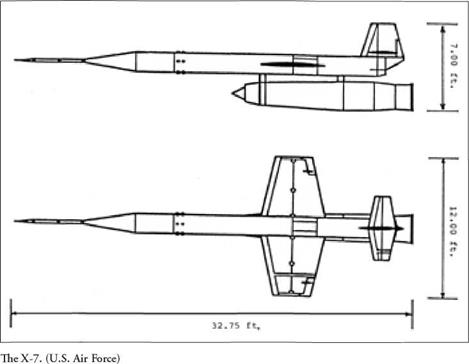
Other materials were already part of mainstream aviation, even in 1954. The Bell X-2 had probably been the first airplane to be built with heat-resistant metals, mounting wings of stainless steel on a fuselage of the nickel alloy К Monel. This gave it a capability of Mach 3.5. Navaho and the XF-103 were both to be built of steel and titanium, while the X-7, a ramjet testbed, was also of steel.34 But all these craft were to fly near Mach 3, whereas the X-15 was to reach Mach 7. This meant that in an era of accelerating change, the X-15 was plausibly a full generation ahead of the most advanced designs that were under development.

The Air Force already had shown its commitment to support flight at high speed by building the Arnold Engineering Development Center (AEDC). Its back­ground dated to the closing days of World War II, when leaders in what was then the Army Air Forces became aware that Germany had been well ahead of the United States in the fields of aerodynamics and jet propulsion. In March 1946, Brigadier General H. I. Hodes authorized planning an engineering center that would be the Air Forces own.

This facility was to use plenty of electrical power to run its wind tunnels, and a committee selected three possible locations. One was Grand Coulee near Spokane, Washington, but was ruled out as being too vulnerable to air attack. The second was Arizona’s Colorado River, near Hoover Dam. The third was the hills north of Alabama, where the Tennessee Valley Authority had its own hydro dams. Senator Kenneth McKellar, the president pro tempore of the Senate and chairman of its

Armed Services Committee, won the new AEDC for his home state of Tennessee by offering to give the Air Force an existing military base, the 40,000-acre Camp Forrest. It was located near Tullahoma, far from cities and universities, but the Air Force was accustomed to operating in remote areas. It accepted this offer in April 1948, with the firm of ARO, Inc. providing maintenance and operation.35

There was no interest in reproducing the research facilities of NACA, for the AEDC was to conduct its own activities. Engine testing was to be a specialty, and the first facility at this center was an engine test installation that had been “liber­ated” from the German firm of BMW But the Air Force soon was installing its own equipment, achieving its first supersonic flow within its Transonic Model Tunnel early in 1953. Then, during 1954, events showed that AEDC was ready to conduct engi­neering development on a scale well beyond anything that NACA could envision.36

That year saw the advent of the 16-Foot Propulsion Wind Tunnel, with a test section 16 feet square. NACA had larger tunnels, but this one approached Mach 3-5 and reached Mach 4.75 under special operating conditions. A Mach of 4.75 had conventionally been associated with the limited run times of blowdown tun­nels, but this tunnel, known as 16S, was a continuous-flow facility. It was unparal­leled for exercising full-scale engines for realistic durations over the entire supersonic range.37

In December 1956 it tested the complete propulsion package of the XF-103, which had a turbojet with an afterburner that functioned as a ramjet. This engine had a total length of 39 feet. But the test section within 16S had a length of 40 feet, which gave room to spare.38 In addition, the similar Engine Test Facility accommo­dated the full-scale SRJ47 engine of Navaho, with a 51-inch diameter that made it the largest ramjet engine ever built.39

The AEDC also jumped into hypersonics with both feet. It already had an Engine Test Facility, a Gas Dynamics Facility (renamed the Von Karman Gas Dynamics Facility in 1959), and a Propulsion Wind Tunnel, the 16S. During 1955 it added a ramjet center to the Engine Test Facility, which many people regarded as a fourth major laboratory.40 Hypersonic wind tunnels were also on the agenda. Two 50-inch installations were in store, to operate respectively at Mach 8 and Mach 10. Both were continuous-flow facilities that used a 92,500-horsepower compressor system. Tunnel B, the Mach 8 facility, became operational in October 1958. Tunnel C, the Mach 10 installation, prevented condensation by heating its air to 1,450°F using a combustion heater and a 12-megawatt resistance heater. It entered operation in May I960.41

The AEDC also conducted basic research in hypersonics. It had not intended to do that initially; it had expected to leave such studies to NACA, with its name reflecting its mission of engineering development. But the fact that it was off in the wilds ofTullahoma did not prevent it from attracting outstanding scientists, some of whom went on to work in hypersonics.

Facilities such as Tunnels В and C could indeed attain hypersonic speeds, but the temperatures of the flows were just above the condensation point of liquid air. There was much interest in achieving far greater temperatures, both to add realism at speeds below Mach 10 and to obtain Mach numbers well beyond 10. Beginning in 1953, the physicist Daniel Bloxsom used the exploding-wire technique, in which a powerful electric pulse vaporizes a thin wire, to produce initial temperatures as high as 5900 K.

This brought the advent of a new high-speed flow facility: the hotshot tunnel. It resembled the shock tube, for the hot gas was to burst a diaphragm and then reach high speeds by expanding through a nozzle. But its run times were considerably longer, reaching one-twentieth of a second compared to less than a millisecond for the shock tube. The first such instrument, Hotshot 1, had a 16-inch test section and entered service early in 1956. In March 1957, the 50-inch Hotshot 2 topped “escape velocity.”42

Against this background, the X-15 drew great interest. It was to serve as a full – scale airplane at Mach 7, when the best realistic tests that AEDC could offer was full-scale engine test at Mach 4.75. Indeed, a speed of Mach 7 was close to the Mach 8 of Tunnel B. The X-15 also could anchor a program of hypersonic studies that soon would have hotshot tunnels and would deal with speeds up to orbital velocity and beyond. And while previous X-planes were seeing their records broken by jet fighters, it would be some time before any other plane flew at such speeds.

The thermal environment of the latest aircraft was driving designers to the use of titanium and steel. The X-15 was to use Inconel X, which had still better properties. This nickel alloy was to be heat-treated and welded, thereby developing valuable shop-floor experience in its use. In addition, materials problems would be pervasive in building a working X-15. The success of a flight could depend on the proper choice of lubricating oil.

The performance of the X-15 meant that it needed more than good aerodynam­ics. The X-2 was already slated to execute brief leaps out of the atmosphere. Thus, in September 1956 test pilot Iven Kincheloe took it to 126,200 feet, an altitude at which his ailerons and tail surfaces no longer functioned.43 In the likely event that future interceptors were to make similar bold leaps, they would need reaction controls—which represented the first really new development in the field of flight control since the Wright Brothers.44 But the X-15 was to use such controls and would show people how to do it.

The X-15 would also need new flight instruments, including an angle-of-attack indicator. Pilots had been flying with turn-and-bank indicators for some time, with these gyroscopic instruments enabling them to determine their attitude while flying blind. The X-15 was to fly where the skies were always clear, but still it needed to determine its angle with respect to the oncoming airflow so that the pilot could set up a proper nose-high attitude. This instrument would face the full heat load of re­entry and had to work reliably.

It thus was not too much to call the X-15 a flying version of AEDC, and high – level Air Force representatives were watching developments closely. In May 1954 Hugh Dryden, Director of NACA, wrote a letter to Lieutenant General Donald Putt, who now was the Air Forces Deputy Chief of Staff, Development. Dryden cited recent work, including that of Beckers group, noting that these studies “will lead to specific preliminary proposals for a new research airplane.” Putt responded with his own letter, stating that “the Scientific Advisory Board has done some think­ing in this area and has formally recommended that the Air Force initiate action on such a program.”45

The director of Wright Air Development Center (WADC), Colonel V. R. Haugen, found “unanimous” agreement among WADC reviews that the Langley concept was technically feasible. These specialists endorsed Langleys engineering solutions in such areas as choice of material, structure, thermal protection, and stability and control. Haugen sent his report to the Air Research and Development Command (ARDC), the parent of WADC, in mid-August. A month later Major General F. B. Wood, an ARDC deputy commander, sent a memo to Air Force Headquarters, endorsing the NACA position and noting its support at WADC. He specifically recommended that the Air Force “initiate a project to design, construct, and operate a new research aircraft similar to that suggested by NACA without delay.”46

Further support came from the Aircraft Panel of the Scientific Advisory Board. In October it responded to a request from the Air Force Chief of Staff, General Nathan Twining, with its views:

“[A] research airplane which we now feel is ready for a program is one involving manned aircraft to reach something of the order of Mach 5 and altitudes of the order of 200,000 to 500,000 feet. This is very analogous to the research aircraft program which was initiated 10 years ago as a joint venture of the Air Force, the Navy, and NACA. It is our belief that a similar co-operative arrangement would be desirable and appropriate now.”47

The meetings contemplated in the Dryden-Putt correspondence were also under way. There had been one in July, at which a Navy representative had presented results of a Douglas Aircraft study of a follow-on to the Douglas Skyrocket. It was to reach Mach 8 and 700,000 feet.48

Then in October, at a meeting of NACA’s Committee on Aerodynamics, Lock­heed’s Clarence “Kelly” Johnson challenged the entire postwar X-planes program. His XF-104 was already in flight, and he pulled no punches in his written statement:

“Our present research airplanes have developed startling performance only by the use of rocket engines and flying essentially in a vacuum. Testing airplanes designed for transonic flight speeds at Mach numbers between 2 and 3 has proven, mainly, the bravery of the test pilots and the fact that where there is no drag, the rocket engine can propel even mediocre aerodynamic forms at high Mach numbers.

I am not aware of any aerodynamic or power plant improvements to air – breathing engines that have resulted from our very expensive research airplane program. Our modern tactical airplanes have been designed almost entirely on NACA and other wind-tunnel data, plus certain rocket model tests….”49

Drawing on Lockheed experience with the X-7, an unpiloted high-speed missile, he called instead for a similar unmanned test aircraft as the way to achieve Mach 7. However, he was a minority of one. Everyone else voted to support the committees resolution:

BE IT HEREBY RESOLVED, That the Committee on Aerodynamics endorses the proposal of the immediate initiation of a project to design and construct a research airplane capable of achieving speeds of the order of Mach number 7 and altitudes of several hundred thousand feet 50

The Air Force was also on board, and the next step called for negotiation of a Memorandum of Understanding, whereby the participants—which included the Navy—were to define their respective roles. Late in October representatives from the two military services visited Hugh Dryden at NACA Headquarters, bringing a draft of this document for discussion. It stated that NACA was to provide techni­cal direction, the Air Force would administer design and construction, and the Air Force and Navy were to provide the funds. It concluded with the words, “Accom­plishment of this project is a matter of national urgency.”51

The draft became the final MOU, with little change, and the first to sign it was Trevor Gardner. He was a special assistant to the Air Force Secretary and had mid – wifed the advent of Atlas a year earlier. James Smith, Assistant Secretary of the Navy for Air, signed on behalf of that service, while Dryden signed as well. These signa­tures all were in place two days before Christmas of 1954. With this, the ground­work was in place for the Air Forces Air Materiel Command to issue a Request for Proposal and for interested aircraft companies to begin preparing their bids.52

As recently as February, all that anyone knew was that this new research air­craft, if it materialized, would be something other than an uprated X-2. The project had taken form with considerable dispatch, and the key was the feasibility study of Beckers group. An independent review at WADC confirmed its conclusions, whereupon Air Force leaders, both in uniform and in mufti, embraced the concept. Approval at the Pentagon then came swiftly.

In turn, this decisiveness demonstrated a willingness to take risks. It is hard today to accept that the Pentagon could endorse this program on the basis of just that one study. Moreover, the only hypersonic wind tunnel that was ready to provide sup­porting research was Becker’s 11-inch instrument; the AEDC hypersonic tunnels were still several years away from completion. But the Air Force was in no mood to hold back or to demand further studies and analyses.

This service was pursuing a plethora of initiatives in jet bombers, advanced fight­ers, and long-range missiles. Inevitably, some would falter or find themselves super­seded, which would lead to charges of waste. However, Pentagon officials knew that the most costly weapons were the ones that America might need and not have in time of war. Cost-benefit analysis had not yet raised its head; Robert McNamara was still in Detroit as a Ford Motor executive, and Washington was not yet a city where the White House would deliberate for well over a decade before ordering the B-l bomber into limited production. Amid the can-do spirit of the 1950s, the X-15 won quick approval.

Designing the Shuttle

In its overall technologies, the space shuttle demanded advances in a host of areas: rocket propulsion, fuel cells and other onboard systems, electronics and com­puters, and astronaut life support. As an exercise in hypersonics, two issues stood out: configuration and thermal protection. The Air Force supported some of the early studies, which grew seamlessly out of earlier work on Aerospaceplane. At

Douglas Aircraft, for instance, Melvin Root had his two-stage Astro, a fully-reusable rocket-powered concept with both stages shaped as lifting bodies. It was to carry a payload of 37,150 pounds, and Root expected that a fleet of such craft would fly 240 times per year. The contemporary Astrorocket of Martin Marietta, in turn, looked like two flat-bottom Dyna-Soar craft set belly to belly, foreshadowing fully – reusable space shuttle concepts of several years later.23

These concepts definitely belonged to the Aerospaceplane era. Astro dated to 1963, whereas Martin’s Astrorocket studies went forward from 1961 to 1965. By mid-decade, though, the name “Aerospaceplane” was in bad odor within the Air Force. The new concepts were rocket-powered, whereas Aerospaceplanes generally had called for scramjets or LACE, and officials referred to these rocket craft as Inte­grated Launch and Re-entry Vehicles (ILRVs).24

Early contractor studies showed a definite preference for lifting bodies, generally with small foldout wings for use when landing. At Lockheed, Hunter’s Star Clipper introduced the stage-and-a-half configuration that mounted expendable propellant tanks to a reusable core vehicle. The core carried the flight crew and payload along with the engines and onboard systems. It had a triangular planform and fitted neatly into a large inverted V formed by the tanks. The McDonnell Tip Tank concept was broadly similar; it also mounted expendable tanks to a lifting-body core.25

At Convair, people took the view that a single airframe could serve both as a core and, when fitted with internal tankage, as a reusable carrier of propellants. This led to the Triamese concept, whereby a triplet of such vehicles was to form a single ILRV that could rise into the sky. All three were to have thermal protection and would re-enter, flying to a runway and deploying their extendable wings. The concept was excessively hopeful; the differing requirements of core and tankage vehicles proved to militate strongly against a one-size-fits-all approach to airframe design. Still, the Triamese approach showed anew that designers were ready to use their imaginations.26

NASA became actively involved in the ongoing ILRV studies during 1968. George Mueller, the Associate Administrator for Manned Space Flight, took a par­ticular interest and introduced the term “space shuttle” by which such craft came to be known. He had an in-house design leader, Maxime Faget of the Manner Space­craft Center, who was quite strong-willed and had definite ideas of his own as to how a shuttle should look. Faget particularly saw lifting bodies as offering no more than mixed blessings: “You avoid wing-body interference,” which brings problems of aerodynamics. “You have a simple structure. And you avoid the weight of wings.” He nevertheless saw difficulties that appeared severe enough to rule out lifting bodies for a practical design.

They had low lift and high drag, which meant a dangerously high landing speed. As he put it, “I don’t think it’s charming to come in at 250 knots.” Deployable wings could not be trusted; they might fail to extend. Lifting bodies also posed serious difficulties in development, for they required a fuselage that could do the work of a wing. This ruled out straightforward solutions to aerodynamic problems; the attempted solutions would ramify throughout the entire design. “They are very difficult to develop,” he added, “because when you’re trying to solve one problem, you’re creating another problem somewhere else.”27 His colleague Milton Silveira, who went on to head the Shuttle Engineering Office at MSC, held a similar view;

“If we had a problem with the aerodynamics on the vehicle, where the body was so tightly coupled to the aerodynamics, you couldn’t simply go out and change the wing. You had to change the whole damn vehicle, so if you make a mistake, being able to correct it was a very difficult thing to do.”28

Faget proposed instead to design his shuttle as a two-stage fully-reusable vehicle, with each stage being a winged airplane having low wings and a thermally-protected flat bottom. The configuration broadly resembled the X-15, and like that craft, it was to re-enter with its nose high and with its underside acting as the heat shield.

Faget wrote that “the vehicle would remain in this flight attitude throughout the entire descent to approximately 40,000 feet, where the velocity will have dropped to less than 300 feet per second. At this point, the nose gets pushed down, and the vehicle dives until it reaches adequate velocity for level flight.” The craft then was to approach a runway and land at a moderate 130 knots, half the landing speed of a lifting body.29

During 1969 NASA sponsored a round of contractor studies that examined anew the range of alternatives. In June the agency issued a directive that ruled out the use of expendable boosters such as the Saturn V first stage, which was quite costly. Then in August, a new order called for the contractors to consider only two – stage fully reusable concepts and to eliminate partially-reusable designs such as Star Clipper and Tip Tank. This decision also was based in economics, for a fully-reus­able shuttle could offer the lowest cost per flight. But it also delivered a new blow to the lifting bodies.30

There was a strong mismatch between lifting-body shapes, which were dictated by aerodynamics, and the cylindrical shapes of propellant tanks. Such tanks had to be cylindrical, both for ease in manufacturing and to hold internal pressure. This pressure was unavoidable; it resulted from boiloff of cryogenic propellants, and it served such useful purposes as stiffening the tanks’ structures and delivering propel­lants to the turbopumps. However, tanks did not fit well within the internal volume of a lifting body; in Faget’s words, “the lifting body is a damn poor container.” The Lockheed and McDonnell designers had bypassed that problem by mounting their tanks externally, with no provision for reuse, but the new requirement of full reus­ability meant that internal installation now was mandatory. Yet although lifting bodies made poor containers, Faget’s wing-body concept was an excellent one. Its fuselage could readily be cylindrical, being given over almost entirely to propellant tankage.31

The design exercises of 1969 covered thermal protection as well as configuration. McDonnell Douglas introduced orbiter designs derived from the HL-10 lifting body, examining 13 candidate configurations for the complete two-stage vehicle. The orbiter had a titanium primary structure, obtaining thermal protection from a hot-structure approach that used external panels of columbium, nickel-chromium, and Rene 41. This study also considered the use of tiles made of a “hardened com­pacted fiber,” which was unrelated to Lockheed’s RSI. However, the company did not recommend this. Those tiles were heavier than panels or shingles of refractory alloy and less durable.32

North American Rockwell took Faget’s two-stage airplane as its preferred approach. It also used a titanium primary structure, with a titanium hot structure protecting the top of the orbiter, which faced a relatively mild thermal environ­ment. For the thermally-protected bottom, North American adopted the work of Lockheed and specified LI-1500 tiles. The design also called for copious use of fiberglass insulation, which gave internal protection to the crew compartment and the cryogenic propellant tanks.33

Lockheed turned the Star Clipper core into a reusable second stage that retained its shape as a lifting body. Its structure was aluminum, as in a conventional airplane. The company was home to LI-1500, and designers considered its use for thermal protection. They concluded, though, that this carried high risk. They recommended instead a hot-structure approach that used corrugated Rene 41 along with shingles of nickel-chromium and columbium. The Lockheed work was independent of that at McDonnell Douglas, but engineers at the two firms reached similar conclusions.34

Convair, home of the Triamese concept, came in with new variants. These included a triplet launch vehicle with a core vehicle that was noticeably smaller than the two propellant carriers that flanked it. Another configuration placed the orbiter on the back of a single booster that continued to mount retractable wings. The orbiter had a primary structure of aluminum, with titanium for the heat-shield sup­ports on the vehicle underside. Again this craft used a hot structure, with shingles of cobalt superalloy on the bottom and of titanium alloy on the top and side surfaces.

Significantly, these concepts were not designs that the companies were prepared to send to the shop floor and build immediately. They were paper vehicles that would take years to develop and prepare for flight. Yet despite this emphasis on the future, and notwithstanding the optimism that often pervades such prelimi­nary design exercises, only North American was willing to recommend RSI as the baseline. Even Lockheed, its center of development, gave it no more than a highly equivocal recommendation. It lacked maturity, with hot structures standing as the approach that held greater promise.35

In the wake of the 1969 studies, NASA officials turned away from lifting bodies. Lockheed continued to study new versions of the Star Clipper, but the lifting body now was merely an alternative. The mainstream lay with Faget’s two-stage fully-reus­able approach, showing rocket-powered stages that looked like airplanes. Very soon, though, the shape of the wings changed anew, as a result of problems in Congress.

The space shuttle was apolitical program, funded by federal appropriations, and it had to make its way within the environment of Washington. On Capitol Hill, an influential viewpoint held that the shuttle was to go forward only if it was a national program, capable of meeting the needs of military as well as civilian users. NASA’s shuttle studies had addressed the agency’s requirements, but this proved not to be the way to proceed. Matters came to a head in the mid-1970 as Congressman Joseph Karth, a longtime NASA supporter, declared that the shuttle was merely the first step on a very costly road to Mars. He opposed funding for the shuttle in com­mittee, and when he did not prevail, he made a motion from the floor of the House to strike the funds from NASA’s budget. Other congressmen assured their colleagues that the shuttle had nothing to do with Mars, and Karth’s measure went down to defeat—but by the narrowest possible margin: a tie vote of 53 to 53. In the Senate, NASA’s support was only slightly greater.36

Such victories were likely to leave NASA undone, and the agency responded by seeking support for the shuttle from the Air Force. That service had tried and failed to build Dyna-Soar only a few years earlier; now it found NASA offering a much larger and more capable space shuttle on a silver platter. However, the Air Force was quite happy with its Titan III launch vehicles and made clear that it would work with NASA only if the shuttle was redesigned to meet the needs of the Pentagon. In particular, NASA was urged to take note of the views of the Air Force Flight Dynamics Laboratory (FDL), where specialists had been engaged in a run­ning debate with Faget since early 1969.

The FDL had sponsored ILRV studies in parallel with the shuttle studies of NASA and had investigated such concepts as Lockheed’s Star Clipper. One of its managers, Charles Cosenza, had directed the ASSET program. Another FDL sci­entist, Alfred Draper, had taken the lead in questioning Faget’s approach. Faget wanted his shuttle stages to come in nose-high and then dive through 15,000 feet to pick up flying speed. With the nose so high, these airplanes would be fully stalled, and the Air Force disliked both stalls and dives, regarding them as preludes to an out-of-control crash. Draper wanted the shuttle to enter its glide while still super­sonic, thereby maintaining much better control.

If the shuttle was to glide across a broad Mach range, from supersonic to sub­sonic, then it would face an important aerodynamic problem: a shift in the wing’s center of lift. Awing generates lift across its entire lower surface, but one may regard this lift as concentrated at a point, the center of lift. At supersonic speeds, this center is located midway between the wing’s leading and trailing edges. At subsonic speeds, this center moves forward and is much closer to the leading edge. To keep an airplane in proper balance, it requires an aerodynamic force that can compensate for this shift.

The Air Force had extensive experience with supersonic fighters and bombers that had successfully addressed this problem, maintaining good control and satisfac­tory handling qualities from Mach 3 to touchdown. Particularly for large aircraft— the B-58 and XB-70 bombers and the SR-71 spy plane—the preferred solution was a delta wing, triangular in shape. Delta wings typically ran along much of the length of the fuselage, extending nearly to the tail. Such aircraft dispensed with horizontal stabilizers at the tail and relied instead on elevons, control surfaces resembling aile­rons that were set at the wing’s trailing edge. Small deflections of these elevons then compensated for the shift in the center of lift, maintaining proper trim and balance without imposing excessive drag. Draper therefore proposed that both stages of Faget’s shuttle have delta wings.37

Faget would have none of this. He wrote that because the only real flying was to take place during the landing approach, a wing design “can be selected solely on the basis of optimization for subsonic cruise and landing.” The wing best suited to this limited purpose would be straight and unswept, like those of fighter planes in World War II. A tail would provide directional stability, as on a conventional airplane, enabling the shuttle to land in standard fashion. He was well aware of the center-of-lift shift but expected to avoid it by avoiding reliance on his wings until the craft was well below the speed of sound. He also believed that the delta would lose on its design merits. To achieve a suitably low landing speed, he argued that the delta would need a large wingspan. A straight wing, narrow in distance between its leading and trailing edges, would be light and would offer relatively little area demanding thermal protection. A delta of the same span, necessary for a moderate landing speed, would have a much larger area than the straight wing. This would add a great deal of weight, while substantially increasing the area that needed ther­mal protection.38

Draper responded with his own view. He believed that Faget’s straight-wing design would be barred on grounds of safety from executing its maneuver of stall, dive, and recovery. Hence, it would have to glide from supersonic speeds through the transonic zone and could not avoid the center-of-lift problem. To deal with it, a good engineering solution called for installation of canards, small wings set well for­ward on the fuselage that would deflect to give the desired control. Canards produce lift and would tend to push the main wings farther to the back. They would be well aft from the outset, for they were to support an airplane that was empty of fuel but that had heavy rocket engines at the tail, placing the craft’s center of gravity far to the rear. The wings’ center of lift was to coincide closely with this center of gravity.

Draper wrote that the addition of canards “will move the wings aft and tend to close the gap between the tail and the wing.” The wing shape that fills this gap is the delta, and Draper added that “the swept delta would most likely evolve.”39

Faget had other critics, while Draper had supporters within NASA. Faget’s thoughts indeed faced considerable resistance within NASA, particularly among the highly skilled test and research pilots at the Flight Research Center. Their spokes­man, Milton Thompson, was certainly a man who knew how to fly airplanes, for he was an X-15 veteran and had been slated to fly Dyna-Soar as well. But in addi­tion, these aerodynamic issues involved matters of policy, which drove the Air Force strongly toward the delta. The reason was that a delta could achieve high crossrange, whereas Fagets straight wing could not.

Crossrange was essential for single-orbit missions, launched from Vandenberg AFB on the California coast, which were to fly in polar orbit. The orbit of a space­craft is essentially fixed with respect to distant stars, but the Earth rotates. In the course of a 90-minute shuttle orbit, this rotation carries the Vandenberg site east­ward by 1,100 nautical miles. The shuttle therefore needed enough crossrange to cover that distance.

The Air Force had operational reasons for wanting once-around missions. A key example was rapid-response satellite reconnaissance. In addition, the Air Force was well aware that problems following launch could force a shuttle to come down at the earliest opportunity, executing a “once-around abort.” NASA’s Leroy Day, a senior shuttle manager, emphasized this point: “If you were making a polar-type launch out ofVandenberg, and you had Max’s straight-wing vehicle, there was no place you could go. You’d be in the water when you came back. You’ve got to go crossrange quite a few hundred miles in order to make land.”40

By contrast, NASA had little need for crossrange. It too had to be ready for once – around abort, but it expected to launch the shuttle from Florida’s Kennedy Space Center on trajectories that ran almost due east. Near the end of its single orbit, the shuttle was to fly across the United States and could easily land at an emergency base. A 1969 baseline program document, “Desirable System Characteristics,” stated that the agency needed only 250 to 400 nautical miles of crossrange, which Faget’s straight wing could deliver with straightforward modifications.41

Faget’s shuttle had a hypersonic L/D of about 0.5- Draper’s delta-wing design was to achieve an L/D of 1.7, and the difference in the associated re-entry trajec­tories increased the weight penalty for the delta. A delta orbiter in any case needed a heavier wing and a larger area of thermal protection, and there was more. The straight-wing craft was to have a relatively brief re-entry and a modest heating rate. The delta orbiter was to achieve its crossrange by gliding hypersonically, executing a hypersonic glide that was to produce more lift and less drag. It also would increase both the rate of heating and its duration. Hence, its thermal protection had to be more robust and therefore heavier still. In turn, the extra weight ramified through­out the entire two-stage shuttle vehicle, making it larger and more costly.42

NASA’s key officials included the acting administrator, George Low, and the Associate Administrator for Manned Space Flight, Dale Myers. They would will­ingly have embraced Faget’s shuttle. But on the military side, the Undersecretary of the Air Force for Research and Development, Michael Yarymovich, had close knowledge of the requirements of the National Reconnaissance Office. He played a key role in emphasizing that only a delta would do.

The denouement came at a meeting in Williamsburg, Virginia, in January 1971. At nearby Yorktown, in 1781, Britain’s Lord Charles Cornwallis had surrendered to General George Washington, thereby ending Americas war of independence. One hundred and ninety years later NASA surrendered to the Air Force, agree­ing particularly to build a delta-wing shuttle with full military crossrange of 1,100 miles. In return, though, NASA indeed won the support from the Pentagon that it needed. Opposition faded on Capitol Hill, and the shuttle program went forward on a much stronger political foundation.43

The design studies of 1969 had counted as Phase A and were preliminary in character. In 1970 the agency launched Phase B, conducting studies in greater depth, with North American Rockwell and McDonnell Douglas as the contractors. Initially they considered both straight-wing and delta designs, but the Williamsburg decision meant that during 1971 they were to emphasize the deltas. These remained as two-stage fully-reusable configurations, which were openly presented at an AIAA meeting in July of that year.

In the primary structure and outer skin of the wings and fuselage, both contrac­tors proposed to use titanium freely. They differed, however, in their approaches to thermal protection. McDonnell Douglas continued to favor hot structures. Most of the underside of the orbiter was covered with shingles of Hastelloy-X nickel superal­loy. The wing leading edges called for a load-bearing structure of columbium, with shingles of coated columbium protecting these leading edges as well as other areas that were too hot for the Hastelloy. A nose cap of carbon-carbon completed the orbiter’s ensemble.44

North American had its own interest in titanium hot structures, specifying them as well for the upper wing surfaces and the upper fuselage. Everywhere else possible, the design called for applying mullite RSI directly to a skin of aluminum. Such tiles were to cover the entire underside of the wings and fuselage, along with much of the fuselage forward of the wings. The nose and leading edges, both of the wings, and the vertical fin used carbon-carbon. In turn, the fin was designed as a hot structure with a skin of Inconel 718 nickel alloy.45

By mid-1971, though, hot structures were in trouble. The new Office of Man­agement and Budget had made clear that it expected to impose stringent limits on funding for the shuttle, which brought a demand for new configurations that could

cut the cost of development. Within weeks, the contractors did a major turnabout. They went over to primary structures of aluminum. They also abandoned hot struc­tures and embraced RSI. Managers were aware that it might take time to develop for operational use, but they were prepared to use ablatives for interim thermal protec­tion, switching to RSI once it was ready.46

What brought this dramatic change? The advent of RSI production at Lockheed was critical. This drew attention from Faget, who had kept his hand in the field of shuttle design, offering a succession of conceptual configurations that had helped to guide the work of the contractors. His most important concept, designated MSC – 040, came out in September 1971 and served as a point of reference. It used alumi­num and RSI.47

“My history has always been to take the most conservative approach,” Faget declared. Everyone knew how to work with aluminum, for it was the most familiar of materials, but titanium was literally a black art. Much of the pertinent shop – floor experience had been gained within the SR-71 program and was classified. Few machine shops had the pertinent background, for only Lockheed had constructed an airplane—the SR-71—that used titanium hot structure. The situation was worse for columbium and the superalloys because these metals had been used mostly in turbine blades. Lockheed had encountered serious difficulties as its machinists and metallurgists wrestled with the use of titanium. With the shuttle facing cost con­straints, no one wanted to risk an overrun while machinists struggled with the prob­lems of other new materials.48

NASA-Langley had worked to build a columbium heat shield for the shuttle and had gained a particularly clear view of its difficulties. It was heavier than RSI but offered no advantage in temperature resistance. In addition, coatings posed serious problems. Silicides showed promise of reusability and long life, but they were fragile and damaged easily. A localized loss of coating could result in rapid oxygen embrit­tlement at high temperatures. Unprotected columbium oxidized readily, and above the melting point of its oxide, 2,730°F, it could burst into flame.49 “The least little scratch in the coating, the shingle would be destroyed during re-entry,” said Faget. Charles Donlan, the shuttle program manager at NASA Headquarters, placed this in a broader perspective in 1983:

“Phase В was the first really extensive effort to put together studies related to the completely reusable vehicle. As we went along, it became increasingly evident that there were some problems. And then as we looked at the development problems, they became pretty expensive. We learned also that the metallic heat shield, of which the wings were to be made, was by no means ready for use. The slightest scratch and you are in trouble.”50

Other refractory metals offered alternatives to columbium, but even when pro­posing to use them, the complexity of a hot structure also militated against their selection. As a mechanical installation, it called for large numbers of clips, brackets, stand-offs, frames, beams, and fasteners. Structural analysis loomed as a formidable task. Each of many panel geometries needed its own analysis, to show with confi­dence that the panels would not fail through creep, buckling, flutter, or stress under load. Yet this confidence might be fragile, for hot structures had limited ability to resist overtemperatures. They also faced the continuing issue of sealing panel edges against ingestion of hot gas during re-entry.51

In this fashion, having taken a long look at hot structures, NASA did an about – face as it turned toward the RSI that Lockheed’s Max Hunter had recommended as early as 1965- The choice of aluminum for the primary structure reflected the excel­lent insulating properties of RSI, but there was more. Titanium offered a poten­tial advantage because of its temperature resistance; hence, its thermal protection might be lighter. However, the apparent weight saving was largely lost due to a need for extra insulation to protect the crew cabin, payload bay, and onboard systems. Aluminum could compensate for its lack of heat resistance because it had higher thermal conductivity than titanium. Hence, it could more readily spread its heat throughout the entire volume of the primary structure.

Designers expected to install RSI tiles by bonding them to the skin, and for this, aluminum had a strong advantage. Both metals form thin layers of oxide when exposed to air, but that of aluminum is more strongly bound. Adhesive, applied to aluminum, therefore held tightly. The bond with titanium was considerably weaker and appeared likely to fail in operational use at approximately 500°E This was not much higher than the limit for aluminum, 350°F, which showed that the tempera­ture resistance of titanium did not lend itself to operational use.52

The move toward RSI and aluminum simplified the design and cut the develop­ment cost. Substantially larger cost savings came into view as well, as NASA moved away from full reusability of its two-stage concepts. The emphasis now was on par­tial reusability, which the prescient Max Hunter had advocated as far back as 1965 when he placed the liquid hydrogen of Star Clipper in expendable external tanks. The new designs kept propellants within the booster, but they too called for the use of external tankage for the orbiter. This led to reduced sizes for both stages and had a dramatic impact on the problem of providing thermal protection for the shuttles booster.

On paper, a shuttle booster amounted to the world s largest airplane, combining the size of a Boeing 747 or C-5A with performance exceeding that of the X-15- It was to re-enter at speeds well below orbital velocity, but still it needed thermal pro­tection, and the reduced entry velocities did not simplify the design. North Ameri­can, for one, specified RSI for its Phase В orbiter, but the company also had to show

T(.*~ JJJJJ SfcICA riD[P J№ *T

™b*F

СОЛГИН1 . BCnoVLlCV E IIHj4Fj

ИЧЮЕ fcHt-QMlCA* «ЯРЧДТ-Сі ^r-HCWUl-ELl

MLLO вли – COATICl 4JUU FILT (СКІШ-ВМи-ГСИ^ГийІ и№41« IHtVi SH. IDCMI

Designing the Shuttle

JfcL3


Thermal-protection tiles for the space shuttle. (NASA)


■ hlrt>4 гни: іеііся ivim


Designing the Shuttle

Designing the Shuttle

that it understood hot structures. These went into the booster, which protected its hot areas with titanium, Inconel 718, carbon-carbon, Rene 41, Haynes 188 steel— and coated columbium.

The move toward external tankage brought several advantages, the most impor­tant of which was a reduction in staging velocity. When designing a two-stage rocket, standard methods exist for dividing the work load between the two stages so as to achieve the lowest total weight. These methods give an optimum staging veloc­ity. A higher value makes the first stage excessively large and heavy; a lower velocity means more size and weight for the orbiter. Ground rules set at NASA’s Marshall Space Flight Center, based on such optimization, placed this staging velocity close to 10,000 feet per second.

But by offloading propellants into external tankage, the orbiter could shrink considerably in size and weight. The tanks did not need thermal protection or heavy internal structure; they might be simple aluminum shells stiffened with internal pressure. With the orbiter being lighter, and being little affected by a change in stag­ing velocity, a recalculation of the optimum value showed advantage in making the tanks larger so that they could carry more propellant. This meant that the orbiter was to gain more speed in flight—and the booster would gain less. Hence, the booster also could shrink in size. Better yet, the reduction in staging velocity eased the problem of booster thermal protection.

Grumman was the first company to pursue this line of thought, as it studied alternative concepts alongside the mainstream fully reusable designs of McDonnell Douglas and North American. Grumman gave a fully-reusable concept of its own, for purposes of comparison, but emphasized a partially-reusable orbiter that put the liquid hydrogen in two external tanks. The liquid oxygen, which was dense and compact, remained aboard this vehicle, but the low density of the hydrogen meant that its tanks could be bulky while remaining light in weight.

The fully-reusable design followed the NASA Marshall Space Flight Center ground rules and showed a staging velocity of 9,750 feet per second. The external – tank configuration cut this to 7,000 feet per second. Boeing, which was teamed with Grumman, found that this substantially reduced the need for thermal protection as such. The booster now needed neither tiles nor exotic metals. Instead, like the X – 15, it was to use its structure as a heat sink. During re-entry, it would experience a sharp but brief pulse of heat, which a conventional aircraft structure could absorb without exceeding temperature limits. Hot areas continued to demand a titanium hot structure, which was to cover some one-eighth of the booster. However, the rest of this vehicle could make considerable use of aluminum.

How could bare aluminum, without protection, serve in a shuttle booster? It was common understanding that aluminum airframes lost strength due to aerodynamic heating at speeds beyond Mach 2, with titanium being necessary at higher speeds. However, this held true for aircraft in cruise, which faced their temperatures con­

tinually. The Boeing booster was to re-enter at Mach 7, matching the top speed of the X-l 5. Even so, its thermal environment resembled a fire that does not burn your hand when you whisk it through quickly Across part of the underside, the vehicle was to protect itself by the simple method of metal with more than usual thickness to cope with the heat. Even these areas were limited in extent, with the contractors noting that “the material gauges [thicknesses] required for strength exceed the mini­mum heat-sink gauges over the majority of the vehicle.”53

McDonnell Douglas went further. In mid-1971 it introduced its own external – tank orbiter that lowered the staging velocity to 6,200 feet per second. Its winged booster was 82 percent aluminum heat sink. Their selected configuration was opti­mized from a thermal standpoint, bringing the largest savings in the weight of ther­mal protection.54 Then in March 1972 NASA selected solid-propellant rockets for the boosters. The issue of their thermal protection now went away entirely, for these big solids used steel casings that were 0.5 inch thick and that provided heat sink very effectively.55

Amid the design changes, NASA went over to the Air Force view and embraced the delta wing. Faget himself accepted it, making it a feature of his MSC-040 con­cept. Then the Office of Management and Budget asked whether NASA might return to Faget’s straight wing after all, abandoning the delta and thereby saving money. Nearly a year after the Williamsburg meeting, Charles Donlan, acting direc­tor of the shuttle program office at Headquarters, ruled this out. In a memo to George Low, he wrote that high crossrange was “fundamental to the operation of the orbiter.” It would enhance its maneuverability, greatly broadening the opportu­nities to abort a mission and perhaps save the lives of astronauts. High crossrange would also provide more frequent opportunities to return to Kennedy Space Center in the course of a normal mission.

Delta wings also held advantages that were entirely separate from crossrange. A delta orbiter would be stable in flight from hypersonic to subsonic speeds, through­out a wide range of nose-high attitudes. The aerodynamic flow over such an orbiter would be smooth and predictable, thereby permitting accurate forecasts of heating during re-entry and giving confidence in the design of the shuttle’s thermal protec­tion. In addition, the delta vehicle would experience relatively low temperatures of 600 to 800°F over its sides and upper surfaces.

By contrast, straight-wing configurations produced complicated hypersonic flow fields, with high local temperatures and severe temperature changes on the wing, body, and tail. Temperatures on the sides of the fuselage would run from 900 to 1,300°F, making the design and analysis of thermal protection more complex. During transition from supersonic to subsonic speeds, the straight-wing orbiter would experience unsteady flow and buffeting, making it harder to fly. This combi­nation of aerodynamic and operational advantages led Donlan to favor the delta for reasons that were entirely separate from those of the Air Force.56

The Loss of Columbia

Thermal protection was delicate. The tiles lacked structural strength and were brittle. It was not possible even to bond them directly to the underlying skin, for they would fracture and break due to their inability to follow the flexing of the skin under its loads. Designers therefore placed an intermediate layer between tiles and skin that had some elasticity and could stretch in response to shuttle skin flexing without transmitting excessive strain to the tiles. It worked; there never was a serious accident due to fracturing of tiles.57

The same was not true of another piece of delicate work: a thermal-protection panel made of carbon that had the purpose of protecting one of the wing leading edges. It failed during re-entry in virtually the final minutes of a flight of Columbia, on 1 February 2003. For want of this panel, that spacecraft broke up over Texas in a shower of brilliant fireballs. All aboard were killed.

The background to this accident lay in the fact that for the nose and leading edges of the shuttle, silica RSI was not enough. These areas needed thermal protec­tion with greater temperature resistance, and carbon was the obvious candidate. It was lighter than aluminum and could be protected against oxidation with a coating. It also had a track record, having formed the primary structure of the Dyna-Soar nose cap and the leading edge of ASSET. Graphite was the standard form, but in contrast to ablative materials, it failed to enter the aerospace mainstream. It was brit­tle and easily damaged and did not lend itself to use with thin-walled structures.

The development of a better carbon began in 1958, with Vought Missiles and Space Company in the forefront. The work went forward with support from the Dyna-Soar and Apollo programs and brought the advent of an all-carbon composite consisting of graphite fibers in a carbon matrix. Existing composites had names such as carbon-phenolic and graphite-epoxy; this one was carbon-carbon.

It retained the desirable properties of graphite in bulk: light weight, tempera­ture resistance, and resistance to oxidation when coated. It had the useful property of actually gaining strength with temperature, being up to 50 percent stronger at 3,000°F than at room temperature. It had a very low coefficient of thermal expansion, which reduced thermal stress. It also had better damage tolerance than graphite.

Carbon-carbon was a composite. As with other composites, Vought engineers fabricated parts of this material by forming them as layups. Carbon cloth gave a point of departure, produced by oxygen-free pyrolysis of a woven organic fiber such as rayon. Sheets of this fabric, impregnated with phenolic resin, were stacked in a mold to form the layup and then cured in an autoclave. This produced a shape made of laminated carbon cloth phenolic. Further pyrolysis converted the resin to its basic carbon, yielding an all-carbon piece that was highly porous due to the loss of volatiles. It therefore needed densification, which was achieved through multiple cycles of reimpregnation under pressure with an alcohol, followed by further pyroly­sis. These cycles continued until the part had its specified density and strength.58

Researchers at Vought conducted exploratory studies during the early 1960s, investigating resins, fibers, weaves, and coatings. In 1964 they fabricated a Dyna – Soar nose cap of carbon-carbon, with this exercise permitting comparison of the new nose cap with the standard versions that used graphite and zirconia tiles. In 1966 this firm crafted a heat shield for the Apollo afterbody, which lay leeward of the curved ablative front face. A year and a half later the company constructed a wind-tunnel model of a Mars probe that was designed to enter the atmosphere of that planet.59

These exercises did not approach the full-scale development that Dyna-Soar and ASSET had brought to hot structures. They definitely were in the realm of the pre­liminary. Still, as they went forward along with Lockheed’s work on silica RSI and GE’s studies of mullite, the work at Vought made it clear that carbon-carbon was likely to take its place amid the new generation of thermal-protection materials.

The shuttle’s design specified carbon-carbon for the nose cap and leading edges, and developmental testing was conducted with care. Structural tests exercised their methods of attachment by simulating flight loads up to design limits, with design temperature gradients. Other tests, conducted within an arc-heated facility, determined the thermal responses and hot-gas leakage characteristics of interfaces between the carbon-carbon and RSI.60

Подпись: Trends in carbon-fiber propertiesПодпись: diesis:: гпмнздіПодпись: КҐЧDesigning the ShuttleПодпись:Подпись: : КОПодпись: SKIПодпись: mm ІЧЛІНЯ ■ Подпись:Подпись: H£>Подпись: Improvements in strength of carbon-carbon after 1981. (AIAA)Other tests used articles that represented substantial portions of the orbiter. An important test item, evaluated at NASA-John – son, reproduced a wing leading edge and measured five by eight feet. It had two leading-edge panels of carbon-carbon set side by side, a section of wing struc­ture that included its main spars, and aluminum skin covered with RSI. It had insulated attachments, internal insulation, and interface seals between the carbon-carbon and the RSI. It withstood simu­lated air loads, launch acoustics, and mission temperature-pres­sure environments, not once but many times.61

There was no doubt that left to themselves, the panels of carbon-carbon that protected the leading edges would have continued to do so. Unfortunately, they were not left to themselves. During the ascent of Columbia, on 16 January 2003, a
large piece of insulating foam detached itself from a strut that joined the external tank to the front of the orbiter. The vehicle at that moment was slightly more than 80 seconds into the flight, traveling at nearly Mach 2.5. This foam struck a carbon – carbon panel and delivered what proved to be a fatal wound.

Ground controllers became aware of this the following day, during a review of high-resolution film taken at the time of launch. The mission continued for two weeks, and in the words of the accident report, investigators concluded that “some localized heating damage would most likely occur during re-entry, but they could not definitively state that structural damage would result.”62

Yet the damage was mortal. Again, in words of the accident report,

Columbia re-entered Earth’s atmosphere with a pre-existing breach

in the leading edge of its left wing_____ This breach, caused by the foam

strike on ascent, was of sufficient size to allow superheated air (probably exceeding 5,000°F) to penetrate the cavity behind the RCC panel. The breach widened, destroying the insulation protecting the wing’s leading edge support structure, and the superheated air eventually melted the thin aluminum wing spar. Once in the interior, the superheated air began to

destroy the left wing___ Finally, over Texas,…the increasing aerodynamic

forces the Orbiter experienced in the denser levels of the atmosphere overcame the catastrophically damaged left wing, causing the Orbiter to fall out of control.63

It was not feasible to go over to a form of thermal protection, for the wing lead­ing edges, that would use a material other than carbon-carbon and that would be substantially more robust. Even so, three years of effort succeeded in securing the foam and the shuttle returned to flight in July 2006 with foam that stayed put.

In addition, people took advantage of the fact that most such missions had already been intended to dock with the International Space Station. It now became a rule that the shuttle could fly only if it were to go there, where it could be inspected minutely prior to re-entry and where astronauts could stay, if necessary, until a dam­aged shuttle was repaired or a new one brought up. In this fashion, rather than the thermal protection being shaped to fit the needs of the missions, the missions were shaped to fit the requirements of having safe thermal protection.64

Designing the Shuttle

X-15: The Technology

Four companies competed for the main contract, covering design and construc­tion of the X-15: Republic, Bell, Douglas, and North American. Each of them brought a substantial amount of hands-on experience with advanced aircraft. Republic, for example, had Alexander Kartveli as its chief designer. He was a highly imaginative and talented man whose XF-105 was nearly ready for first flight and whose XF-103 was in development. Republic had also built a rocket plane, the XF – 91- This was a jet fighter that incorporated the rocket engine of the X-l for an extra boost in combat. It did not go into production, but it flew in flight tests.

Still, Republic placed fourth in the competition. Its concept rated “unsatisfac­tory” as a craft for hypersonic research, for it had a thin outer fuselage skin that appeared likely to buckle when hot. The overall proposal rated no better than aver­age in a number of important areas, while achieving low scores in Propulsion System and Tanks, Engine Installation, Pilot’s Instruments, Auxiliary Power, and Landing Gear. In addition, the company itself was judged as no more than “marginal” in the key areas of Technical Qualifications, Management, and Resources. The latter included availability of in-house facilities and of an engineering staff not committed to other projects.53

Bell Aircraft, another contender, was the mother of research airplanes, having built the X-l series as well as the X-2. This firm therefore had direct experience both with advanced heat-resistant metals and with the practical issues of powering piloted aircraft using liquid-fuel rocket engines. It even had an in-house group that was building such engines. Bell also was the home of the designers Robert Woods and Walter Dornberger, with the latter having presided over the V-2.

Dornberger’s Bomi concept already was introducing the highly useful concept of hot structures. These used temperature-resistant alloys such as stainless steel. Wings might be covered with numerous small and very hot metal panels, resembling shin­gles, that would radiate heat away from the aircraft. Overheating would be particu­larly severe along the leading edges of wings; these could be water-cooled. Insulation could protect an internal structure that would withstand the stresses and forces of flight; active cooling could protect a pilot’s cockpit and instrument compartment. Becker described these approaches as “the first hypersonic aircraft hot structures concepts to be developed in realistic meaningful detail.”54

Even so, Bell ranked third. Historian Dennis Jenkins writes that within the pro­posal, “almost every innovation they proposed was hedged in such a manner as to make the reader doubt that it would work. The proposal itself seemed rather poorly organized and was internally inconsistent (i. e., weights and other figures frequently differed between sections).”55 Yet the difficulties ran deeper and centered on the specifics of its proposed hot structure.

Bell adopted the insulated-structure approach, with the primary structure being of aluminum, the most familiar of aircraft materials and the best understood. Cor­rugated panels of Inconel X, mounted atop the aluminum, were to provide insula­tion. Freely-suspended panels of this alloy, contracting and expanding with ease, were to serve as the outer skin.

Yet this concept was quite unsuitable for the X-15, both on its technical merits and as a tool for research. A major goal of the program was to study aircraft struc­tures at elevated temperatures, and this would not be possible with a primary struc­ture of cool aluminum. There were also more specific deficiencies, as when Bell’s thermal analysis assumed that the expanding panels of the outer shell would prevent leakage of hot air from the boundary layer. However, the evaluation made the flat statement, “leakage is highly probable.” Aluminum might not withstand the result­ing heating, with the loss of even one such panel leading perhaps to destructive heating. Indeed, the Bell insulated structure appeared so sensitive that it could be trusted to successfully complete only three of 13 reference flights.56

Another contender, Douglas Aircraft, had shared honors with Bell in building previous experimental aircraft. Its background included the X-3 and the Skyrocket, which meant that Douglas also had people who knew how to integrate a liquid rocket engine with an airplane. This company’s concept came in second.

Its design avoided reliance on insulated structures, calling instead for use of a heat sink. The material was to be a lightweight magnesium alloy that had excellent

X-15: The Technology

The North American X-15. (NASA)

heat capacity. Indeed, its properties were so favorable that it would reach tempera­tures of only 600°F, while an Inconel X heat-sink airplane would go to 1,200°F.

Again, though, this concept missed the point. Managers wanted a vehicle that could cope successfully with temperatures of 1,200°F, to lay groundwork for opera­tional fighters that could fly well beyond Mach 3. In addition, the concept had virtually no margin for temperature overshoots. Its design limit of 600°F was right on the edge of a regime of which its alloy lost strength rapidly. At 680°F, its strength could fall off by 90 percent. With magnesium being flammable, there was danger of fire within the primary structure itself, with the evaluation noting that “only a small area raised to the ignition temperature would be sufficient to destroy the aircraft.”57

Then there was North American, the home of Navaho. That missile had not flown, but its detailed design was largely complete and specified titanium in hot areas. This meant that that company knew something about using advanced metals. The firm also had a particularly strong rocket-engine group, which split off during 1955 to form a new corporate division called Rocketdyne. Indeed, engines built by that association had already been selected for Atlas.58

North American became the winner. It paralleled the thinking at Douglas by independently proposing its own heat-sink structure, with the material being Inco­nel X. This concept showed close similarities to that of Becker’s feasibility study a year earlier. Still, this was not to say that the deck was stacked in favor of Beck­er’s approach. He and his colleagues had pursued conceptual design in a highly impromptu fashion. The preliminary-design groups within industry were far more experienced, and it had appeared entirely possible that these experts, applying their seasoned judgment, might come up with better ideas. This did not happen. Indeed, the Bell and Douglas concepts failed even to meet an acceptable definition of the new research airplane. By contrast, the winning concept from North American amounted to a particularly searching affirmation of the work of Becker’s group.59

How had Bell and Douglas missed the boat? The government had set forth per­formance requirements, which these companies both had met. In the words of the North American proposal, “the specification performance can be obtained with very moderate structural temperatures.” However, “the airplane has been designed to tolerate much more severe heating in order to provide a practical temperature band within which exploration can be conducted.”

In Jenkins’s words, “the Bell proposal…was terrible—you walked away not entirely sure that Bell had committed themselves to the project. The exact opposite was true of the North American proposal. From the opening page you knew that North American understood what was trying to be accomplished with the X-15 program and had attempted to design an airplane that would help accomplish the task—not just meet the performance specifications (which did not fully describe the intent of the program).”60 That intent was to build an aircraft that could accomplish research at 1,200°F and not merely meet speed and altitude goals.

The overall process of proposal evaluation cast the competing concepts in sharp relief, heightening deficiencies and emphasizing sources of potential difficulty. These proposals also received numerical scores, while another basis for comparison involved estimated program costs:

North American

81.5 percent

$56.1 million

Douglas Aircraft

80.1

36.4

Bell Aircraft

75.5

36.3

Republic Aviation

72.2

47.0

North Americans concept thus was far from perfect, while Republic’s repre­sented a serious effort. In addition, it was clear that the Air Force—which was to foot most of the bill—was willing to pay for what it would get. The X-15 program thus showed budgetary integrity, with the pertinent agencies avoiding the tempta­tion to do it on the cheap.61

On 30 September 1955, letters went out to North American as well as to the unsuccessful bidders, advising them of the outcome of the competition. With this, engineers now faced the challenge of building and flying the X-15 as a practical exercise in hypersonic technology. Accordingly, it broke new ground in such areas as metallurgy and fabrication, onboard instruments, reaction controls, pilot training, the pilots pressure suit, and flight simulation.62

Inconel X, a nickel alloy, showed good ductility when fully annealed and had some formability. When severely formed or shaped, though, it showed work-hardening, which made the metal brittle and prone to crack. Workers in the shop addressed this problem by forming some parts in stages, annealing the workpieces by heating them between each stage. Inconel X also was viewed as a weldable alloy, but some welds tended to crack, and this problem resisted solution for some time. The solution lay in making welds that were thicker than the parent material. After being ground flat, their surfaces were peened—bombarded with spherical shot—and rolled flush with the parent metal. After annealing, the welds often showed better crack resistance than the surrounding Inconel X.

A titanium alloy was specified for the internal structure of the wings. It proved difficult to weld, for it became brittle by reacting with oxygen and nitrogen in the air. It therefore was necessary to enclose welding fixtures within enclosures that could be purged with an inert gas such as helium and to use an oxygen-detecting device to determine the presence of air. With these precautions, it indeed proved possible to weld titanium while avoiding embrittlement.63

Greases and lubricants posed their own problems. Within the XT5, journal and antifriction bearings received some protection from heat and faced operat­ing temperatures no higher than 600°F. This nevertheless was considerably hotter than engineers were accustomed to accommodating. At North American, candidate lubricants underwent evaluation by direct tests in heated bearings. Good greases protected bearing shafts for 20,000 test cycles and more. Poor greases gave rise to severe wearing of shafts after as few as 350 cycles.64

In contrast to conventional aircraft, the X-15 was to fly out of the sensible atmo­sphere and then re-enter, with its nose high. It also was prone to yaw while in near­vacuum. Hence, it needed a specialized instrument to determine angles of attack and of sideslip. This took form as the “Q-ball,” built by the Nortronics Division of Northrop Aircraft. It fitted into the tip of the X-15’s nose, giving it the appearance of a greatly enlarged tip of a ballpoint pen.

The ball itself was cooled with liquid nitrogen to withstand air temperatures as high as 3,500°F. Orifices set within the ball, along yaw and pitch planes, measuring differential pressures. A servomechanism rotated the ball to equalize these pressures by pointing the balls forward tip directly into the onrushing airflow. With the direction of this flow thus established, the pilot could null out any sideslip. He also could raise the nose to a desired angle of attack. “The Q-ball is a go-no go item,” the test pilot Joseph Walker told Time magazine in 1961. “Only if she checks okay do we go.”65

To steer the aircraft while in flight, the X-15 mounted aerodynamic controls. These retained effectiveness at altitudes well below 100,000 feet. However, they lost

effectiveness between 90,000 and 100,000 feet. The X-15 therefore incorporated reac­tion controls, which were small thrusters fueled with hydrogen peroxide. Nose-mounted units controlled pitch and yaw. Other units, set near the wingtips, gave control of roll.

X-15: The TechnologyNo other research airplane had ever flown with such thrust­ers, although the X-1B con­ducted early preliminary experi­ments and the X-2 came close to needing them in 1956. During a flight in September of that year, the test pilot Iven Kinche – loe took it to 126,200 feet. At that altitude, its aerodynamic controls were useless. Kincheloe

, . . , . . flew a ballistic arc, experiencing

Attitude control or a hypersonic airplane using aerody – г 1

namic controls and reaction controls. (U. S. Air Force) near-weightlessness for close to

a minute. His airplane banked to the left, but he did not try to counter this movement, for he knew that his X-2 could easily go into a deadly tumble.66

In developing reaction controls, an important topic for study involved determin­ing the airplane handling qualities that pilots preferred. Initial investigations used an analog computer as a flight simulator. The “airplane” was disturbed slightly; a man used a joystick to null out the disturbance, achieving zero roll, pitch, and yaw. These experiments showed that pilots wanted more control authority for roll than for pitch or yaw. For the latter, angular accelerations of 2.5 degrees per second squared were acceptable. For roll, the preferred control effectiveness was two to four times greater.

Flight test came next. The X-2 would have served splendidly for this purpose, but only two had been built, with both being lost in accidents. At NACA’s High – Speed Flight Station, investigators fell back on the X-lB, which was less capable but still useful. In preparation for its flights with reaction controls, the engineers built a simulator called the Iron Cross, which matched the dimensions and inertial characteristics of this research plane. A pilot, sitting well forward along the central arm, used a side-mounted control stick to actuate thrusters that used compressed
nitrogen. This simulator was mounted on a universal joint, which allowed it to move freely in yaw, pitch, and roll.

Reaction controls went into the X-1B late in 1957. The test pilot Neil Arm­strong, who walked on the Moon 12 years later, made three flights in this research plane before it was grounded in mid-1958 due to cracks in its fuel tank. Its peak altitude during these three flights was 55,000 feet, where its aerodynamic controls readily provided backup. The reaction controls then went into an F-104, which reached 80,000 feet and went on to see much use in training X-15 pilots. When the X-15 was in flight, these pilots had to transition from aerodynamic controls to reaction controls and back again. The complete system therefore provided overlap. It began blending in the reaction controls at approximately 85,000 feet, with most pilots switching to reaction controls exclusively by 100,000 feet.67

Since the war, with aircraft increasing in both speed and size, it had become increasingly impractical for a pilot to exert the physical strength to operate a plane’s ailerons and elevators merely by moving the control stick in the cockpit. Hydrauli­cally-boosted controls thus were in the forefront, resembling power steering in a car. The X-15 used such hydraulics, which greatly eased the workload on a test pilots muscles. These hydraulic systems also opened the way for stability augmentation systems of increasing sophistication.

Stability augmentation represented a new refinement of the autopilot. Conven­tional autopilots used gyroscopes to detect deviations from a plane’s straight and level course. These instruments then moved an airplane’s controls so as to null these deviations to zero. For high-performance jet fighters, the next step was stability augmentation. Such aircraft often were unstable in flight, tending to yaw or roll; indeed, designers sometimes enhanced this instability to make them more maneu­verable. Still, it was quite wearying for a pilot to have to cope with this. A stability augmentation system made life in the cockpit much easier.

Such a system used rate gyros, which detected rates of movement in pitch, roll, and yaw at so many degrees per second. The instrument then responded to these rates, moving the controls somewhat like before to achieve a null. Each axis of this control had “gain,” defining the proportion or ratio between a sensed rate of angu­lar motion and an appropriate deflection of ailerons or other controls. Fixed-gain systems worked well; there also were variable-gain arrangements, with the pilot set­ting the value of gain within the cockpit. This addressed the fact that the airplane might need more gain in thin air at high altitude, to deflect these surfaces more strongly.68

The X-15 program built three of these aircraft. The first two used a stability aug­mentation system that incorporated variable gain, although in practice these aircraft flew well with constant values of gain, set in flight.69 The third replaced it with a more advanced arrangement that incorporated something new: adaptive gain. This

was a variable gain, which changed automatically in response to flight conditions. Within the Air Force, the Flight Control Laboratory at WADC had laid ground­work with a program dating to 1955- Adaptive-gain controls flew aboard F-94 and F-101 test aircraft. The X-15 system, the Minneapolis Honeywell MH-96, made its first flight in December 1961.70

How did it work? When a pilot moved the control stick, as when changing the pitch, the existing value of gain in the pitch channel caused the aircraft to respond at a certain rate, measured by a rate gyro. The system held a stored value of the optimum pitch rate, which reflected preferred handling qualities. The adaptive-gain control compared the measured and desired rates and used the difference to deter­mine a new value for the gain. Responding rapidly, this system enabled the airplane to maintain nearly constant control characteristics over the entire flight envelope.71

The MH-96 made it possible to introduce the X-15’s blended aerodynamic and reaction controls on the same control stick. This blending occurred automatically in response to the changing gains. When the gains in all three channels—roll, pitch, and yaw—reached 80 percent of maximum, thereby indicating an imminent loss of effectiveness in the aerodynamic controls, the system switched to reaction controls. During re-entry, with the airplane entering the sensible atmosphere, the system returned to aerodynamic control when all the gains dropped to 60 percent.72

The X-15 flight-control system thus stood three steps removed from the conven­tional stick-and-cable installations of World War II. It used hydraulically-boosted controls; it incorporated automatic stability augmentation; and with the MH-96, it introduced adaptive gain. Fly-by-wire systems lay ahead and represented the next steps, with such systems being built both in analog and digital versions.

Analog fly-by-wire systems exist within the F-16A and other aircraft. A digital system, as in the space shuttle, uses a computer that receives data both from the pilot and from the outside world. The pilot provides input by moving a stick or sidearm controller. These movements do not directly actuate the ailerons or rudder, as in days of old. Instead, they generate signals that tell a computer the nature of the desired maneuver. The computer then calculates a gain by applying control laws, which take account of the planes speed and altitude, as measured by onboard instruments. The computer then sends commands down a wire to hydraulic actua­tors co-mounted with the controls to move or deflect these surfaces so as to comply with the pilot’s wishes.73

The MH-96 fell short of such arrangements in two respects. It was analog, not digital, and it was a control system, not a computer. Like other systems executing automatic control, the MH-96 could measure an observed quantity such as pitch rate, compare it to a desired value, and drive the difference to zero. But the MH-96 was wholly incapable of implementing a control law, programmed as an algebraic expression that required values of airspeed and altitude. Hence, while the X-15 with

MH-96 stood three steps removed from the fighters of the recent war, it was two steps removed from the digital fly-by-wire control of the shuttle.

The X-l 5 also used flight simulators. These served both for pilot training and for development of onboard systems, including the reaction controls and the MH-96. The most important flight simulator was built by North American. It replicated the X-l5 cockpit and included actual hydraulic and control-system hardware. Three analog computers implemented equations of motion that governed translation and rotation of the X-l 5 about all three axes, transforming pilot inputs into instrument displays.74

Flight simulators dated to the war. The famous Link Trainer introduced over half a million neophytes to their cockpits. The firm of Link Aviation added analog computers in 1949, within a trainer that simulated flight in a jet fighter.75 In 1955, when the X-l 5 program began, it was not at all customary to use flight simulators to support aircraft design and development. But program managers turned to such simulators because they offered effective means to study new issues in cockpit dis­plays, control systems, and aircraft handling qualities.

Flight simulation showed its value quite early. An initial X-l5 design proved excessively unstable and difficult to control. The cure lay in stability augmentation. A 1956 paper stated that this had “heretofore been considered somewhat of a luxury for high-speed aircraft,” but now “has been demonstrated as almost a necessity,” in all three axes, to ensure “consistent and successful entries” into the atmosphere.76

The North American simulator, which was transferred to the NACA Flight Research Center, became critical in training X-l 5 pilots as they prepared to execute specific planned flights. A particular mission might take little more than 10 min­utes, from ignition of the main engine to touchdown on the lakebed, but a test pilot could easily spend 10 hours making practice runs in this facility. Training began with repeated trials of the normal flight profile, with the pilot in the simulator cock­pit and a ground controller close at hand. The pilot was welcome to recommend changes, which often went into the flight plan. Next came rehearsals of off-design missions: too much thrust from the main engine, too high a pitch angle when leav­ing the stratosphere.

Much time was spent practicing for emergencies. The X-l 5 had an inertial refer­ence unit that used analog circuitry to display attitude, altitude, velocity, and rate of climb. Pilots dealt with simulated failures in this unit, attempting to complete the normal mission or, at least, execute a safe return. Similar exercises addressed failures in the stability augmentation system. When the flight plan raised issues of possible flight instability, tests in the simulator used highly pessimistic assumptions concern­ing stability of the vehicle. Other simulated missions introduced in-flight failures of the radio or Q-ball. Premature engine shutdowns imposed a requirement for safe landing on an alternate lakebed, which was available for emergency use.77

The simulations indeed were realistic in their cockpit displays, but they left out an essential feature: the g-loads, produced both by rocket thrust and by deceleration during re-entry. In addition, a failure of the stability augmentation system, during re-entry, could allow the airplane to oscillate in pitch or yaw. This would change its drag characteristics, imposing a substantial cyclical force.

To address such issues, investigators installed a flight simulator within the gon­dola of a centrifuge at the Naval Air Development Center in Johnsville, Pennsylva­nia. The gondola could rotate on two axes while the centrifuge as a whole was turn­ing. It not only produced g-forces, but its g-forces increased during the simulated rocket burn. The centrifuge imposed such forces anew during reentry, while adding a cyclical component to give the effect of a yaw or pitch oscillation.78

Not all test pilots rode the centrifuge. William “Pete” Knight, who stood among the best, was one who did not. His training, coupled with his personal coolness and skill, enabled him to cope even with an extreme emergency. In 1967, during a planned flight to 250,000 feet, an X-l5 experienced a complete electrical failure while climbing through 107,000 feet at Mach 4. This failure brought the shutdown of both auxiliary power units and hence of both hydraulic systems. Knight, the pilot, succeeded in restarting one of these units, which restored hydraulic power. He still had zero electrical power, but with his hydraulics, he now had both his aerody­namic and reaction controls. He rode his plane to a peak of 173,000 feet, re-entered the atmosphere, made a 180-degree turn, and glided to a safe landing on Mud Lake near Tonopah, Nevada.79

During such flights, as well as during some exercises in the centrifuge, pilots wore a pressure suit. Earlier models had already been good enough to allow the test pilot Marion Carl to reach 83,235 feet in the Douglas Skyrocket in 1953. Still, some of those versions left much to be desired. Time magazine, in 1952, discussed an Air Force model that allowed a pilot to breathe, but “with difficulty. His hands, not fully pressurized, swell up with blue venous blood. His throat is another trouble spot; the medicos have not yet learned how to pressurize a throat without strangling its owner.”80

The David G. Clark Company, a leading supplier of pressure suits for Air Force flight crews, developed a greatly improved model for the X-l5. Such suits tended to become rigid and hard to bend when inflated. This is also true of a child’s long balloon, with an internal pressure that only slightly exceeds that of the atmosphere. The X-l 5 suit was to hold five pounds per square inch of pressure, or 720 pounds per square foot. The X-l 5 cockpit had its own counterbalancing pressure, but it could (and did) depressurize at high altitude. In such an event, the suit was to pro­tect the test pilot rather than leave him immobile.

The solution used an innovative fabric that contracted in circumference while it stretched in length. With proper attention to the balance between these two effects,

the suit maintained a constant volume when pressurized, enhancing a pilot’s free­dom of movement. Gloves and boots were detachable and zipped to this fabric. The helmet was joined to the suit with a freely-swiveling ring that gave full mobility to the head. Oxygen flowed into the helmet; exhalant passed through valves in a neck seal and pressurized the suit. Becker later described it as “the first practical full-pres­sure suit for pilot protection in space.”81

Thus accoutered, protected for flight in near-vacuum, X-15 test pilots rode their rockets as they approached the edge of space and challenged the hypersonic frontier. They returned with results galore for project scientists—and for the nation.

The Fading,. the Comeback

During the 1960s and 1970s, work in re-entry went from strength to strength. The same was certainly not true of scramjets, which reached a peak of activity in the Aerospaceplane era and then quickly faded. Partly it was their sheer difficulty, along with an appreciation that whatever scramjets might do tomorrow, rockets were already doing today. Yet the issues went deeper.

The 1950s saw the advent of antiaircraft missiles. Until then, the history of air power had been one of faster speeds and higher altitudes. At a stroke, though, it became clear that missiles held the advantage. A hot fighter plane, literally hot from aerodynamic heating, now was no longer a world-class dogfighter; instead it was a target for a heat-seeking missile.

When antiaircraft no longer could outrace defenders, they ceased to aim at speed records. They still needed speed but not beyond a point at which this requirement would compromise other fighting qualities. Instead, aircraft were developed with an enhanced ability to fly low, where missiles could lose themselves in ground clutter, and became stealthy. In 1952, late in the dogfight era, Clarence “Kelly” Johnson designed the F-104 as the “missile with a man in it,” the ultimate interceptor. No one did this again, not after the real missiles came in.

This was bad news for ramjets. The ramjet had come to the fore around 1950, in projects such as Navaho, Bomarc, and the XF-103, because it offered Mach 3 at a time when turbojets could barely reach Mach 1. But Mach 3, when actually achieved in craft such as the XB-70 and SR-71, proved to be a highly specialized achievement that had little to do with practical air power. No one ever sent an SR-71 to conduct close air support at subsonic speed, while the XB-70 gave way to its predecessor, the B-52, because the latter could fly low whereas the XB-70 could not.

Ramjets also faltered on their merits. The ramjet was one of two new airbreath – ers that came forth after the war, with the other being the turbojet. Inevitably this set up a Darwinian competition in which one was likely to render the other extinct. Ramjets from the start were vulnerable, for while they had the advantage of speed, they needed an auxiliary boost from a rocket or turbojet. Nor was it small; the Navaho booster was fully as large as the winged missile itself.

The problem of compressor stall limited turbojet performance for a time. But from 1950 onward, several innovations brought means of dealing with it. They led to speedsters such as the F-104 and F-105, operational aircraft that topped Mach 2, along with the B-58 which also did this. The SR-71, in turn, exceeded Mach 3. This meant that there was no further demand for ramjets, which were not selected for new aircraft.

The ramjet thus died not only because its market was lost to advanced turbojets, but because the advent of missiles made it clear that there no longer was a demand for really fast aircraft. This, in turn, was bad news for scramjets. The scramjet was an advanced ramjet, likely to enter the aerospace mainstream only while ramjets remained there. The decline of the ramjet trade meant that there was no industry that might build scramjets, no powerful advocates that might press for them.

The scramjet still held the prospective advantage of being able to fly to orbit as a single stage. With Aerospaceplane, the Air Force took a long look as to whether this was plausible, and the answer was no, at least not soon. With this the scramjet lost both its rationale in the continuing pursuit of high speed and the prospect of an alternate mission—ascent to orbit—that might allow it to bypass this difficulty.

In its heyday the scramjet had stood on the threshold of mainstream research and development, with significant projects under way at General Electric and United Air­craft Research Laboratories, which was affiliated with Pratt & Whitney. As scram­jets faded, though, even General Applied Science Laboratories (GASL), a scramjet center that had been founded by Antonio Ferri himself, had to find other activities. For a time the only complete scramjet lab in business was at NASA-Langley.

And then—lightning struck. President Ronald Reagan announced the Strategic Defense Initiative (SDI), which brought the prospect of a massive new demand for access to space. The Air Force already was turning away from the space shuttle, while General Lawrence Skantze, head of the Air Force Systems Command, was strongly interested in alternatives. He had no background in scramjets, but he embraced the concept as his own. The result was the National Aerospace Plane (NASP) effort, which aimed at airplane-like flight to orbit.

In time SDI faded as well, while lessons learned by researchers showed that NASP offered no easy path to space flight. NASP faded in turn and with it went hopes for a new day for hypersonics. Final performance estimates for the prime NASP vehicle, the X-30, were not terribly far removed from the early and optimistic estimates that had made the project appear feasible. Still, the X-30 design was so sensitive that even modest initial errors could drive its size and cost beyond what the Pentagon was willing to accept.

Facing the Heat Barrier: a History of Hypersonics

It is a pleasure to note the numerous people who helped me with this book. My personal involvement in hypersonics dates to 1982. I wrote a number of free-lance articles, along with three book-length reviews, before beginning work on the present book in 1999. During these past two decades, several dozen people kindly granted interviews in the course of these assignments. This book draws on discussions with the following:

J. Leland Atwood, Robert Barthelemy, George Baum, Fred Billig, Richard Booton, Peter Bradshaw, William Cabot, Robert Cooper, Scott Crossfield,

Paul Czysz, William Dannevik, Anthony duPont, James Eastham, John Erdos, Maxime Faget, George Gleghorn, Edward Hall, Lawrence Huebner, Antony Jameson, Robert Jones, Arthur Kantrowitz, James Keller, George Keyworth, William “Pete” Knight, John Lumley, Luigi Martinelli, Robert Mercier, Parviz Moin, Gerhard Neumann, Louis Nucci, Philip Parrish, John Pike, Heinz Pitsch, Jerry Rising, Anatol Roshko, Paul Rubbert, Ron Samborsky, Robert Sanator, George Schairer, David Scott, Christian Stem – mer, Arthur Thomas, Steven Weinberg, and Robert Williams.

In the NASA History Division, NASA Chief Historian Steven Dick served effec­tively as my editor. NASA-Langley has an excellent library, where I received par­ticular help from Sue Miller and Garland Gouger. In addition, Dill Hunley, the historian at NASA-Dryden, hosted me for a week-long visit. The archivist, Archie DiFante, gave similar strong support during my visits to Maxwell Air Force Base. The Science and Technology Corporation, administered my work under subcon­tract, for which I give thanks to Andrea Carden, Carla Coombs, Sue Crotts, Marion Kidwell, and George Wood.

Dennis Jenkins provided me with documents and answered a number of ques­tions. The artists Don Dixon and Chris Butler, who helped me on previous book projects, provided valuable assistance on this one as well. In addition, as for previous books, Phyllis LaVietes served as my secretary.

This book reflects my interest in the National Aerospace Plane effort, which I covered as a writer beginning in 1985. It is a pleasure to recall my ongoing friend­ships with Robert Williams, who gave me access to sources; Fred Billig, who helped me learn the trade of hypersonics; and Arthur Kantrowitz, who was present at the beginning. These three stand out among the dozens of people with whom it has been my privilege to conduct interviews and discussions.