Category A VERTICAL EMPIRE

Introduction

It has been said that Britain acquired an empire in a fit of absent-mindedness. It might also be said that it acquired a rocketry programme in a similar fit of absent-mindedness. The UK space programme, or rocketry programme, has always been so low key that the public perception is that the UK has never even had a space programme. Yet for a time in the late 1950s and throughout the 1960s, the programme was technically as advanced as any in the world. If it did not achieve the high profiles of Sputnik, Vostok or Apollo, it is in the main because the projects were less ambitious, subject to much greater financial restrictions, and had a more modest goal. Most of the work was driven by the needs of the military. This was true too in the USA and USSR, but there the civilian effort also became caught up in the Cold War propaganda battles. Kennedy’s cry to arms ‘… to put a man on the moon before this decade is out …’ had no resonances in the UK, and the motives that drove many of the other projects in the US were also very often military in origin, even if they have been used in civilian guise. GPS began as a way for nuclear submarines to fix their position so they could launch their missiles more accurately.

It must be admitted at the outset that almost all the work described here began life as a military project designed to obliterate cities and their inhabitants. The biggest project of all described in this book is Blue Streak, whose sole purpose was to launch hydrogen bombs at the USSR. It was only later that its application to a satellite launcher was seized upon as a political fig leaf for an embarrassed Government, and even then many of the potential satellites might well have been military. Likewise, Blue Steel was intended to deliver megaton warheads. Black Knight was a research vehicle whose initial function was to act as a test bed for Blue Streak and to research re-entry vehicles for nuclear warheads. Black Arrow and Skylark were the only major projects discussed here whose applications were intended to be solely civilian and scientific.

In the end, though, the British work on rocketry and satellite launchers died, mainly as a consequence of lack of funding, political vacillation and a perceived lack of need either for satellites or other forms of space research, whether military or commercial. Although now there is a developing and thriving international commercial market for the launching of communications satellites in particular, the British rocketry programme is certainly now completely dead and there is no prospect of resurrection. All the engineers with any relevant experience have retired long ago. All the infrastructure has disappeared. It is ironic that the systems that were built and tested in the 1960s, and then abandoned, could have been commercially successful in the 1980s and 1990s. It was, perhaps, a penalty paid for being too early in the field.

To understand the story fully, we have to go back more than half a century, to the early days of the Cold War. During the Cold War era, the USA and USSR were driven by ideological pressures that the UK did not experience. Each feared the other and their systems of government. In addition, when it came to development and production of hardware, they had vastly greater resources than the UK. Indeed, the USSR can be said to have ‘lost’ the Cold War in the sense that it was driven into final collapse in part by the demands of the military and space programmes on its shaky economy. In some sense that was true for Britain as well: after Blue Streak, there was little further attempt to develop a purely indigenous deterrent system. Since the mid-1960s, the deterrent has been maintained at minimal expense.

Politically, missiles and the nuclear threat meant very different things to the UK compared with the USA and USSR. The UK had no hope of ‘winning’ a nuclear war, given its limited geography (no-one else did, but there was a perception among some in America that a nuclear war was ‘winnable’). America and Russia were driven by a paranoid fear that the one was intent on the other’s destruction, and the ideologies of the two were so far apart as to be virtually irreconcilable, despite ideas of ‘peaceful co-existence’.

The UK had no such geopolitical or ideological dynamic. It had a considerable interest in the state of Europe and the Continental balance of power, as it always has had, but that interest was to be subsumed into NATO, whose purpose, as its first Secretary General, Lord Ismay, put it, was ‘to keep the Americans in, the Russians out, and the Germans down’. The UK had also suffered tremendous economic damage in the Second World War, from which it took a long time to recover. In addition to the expenses of maintaining a far flung Empire, it also had to provide an army of occupation for Germany. One of the problems of wanting to be a Great Power is taking on the burdens and expenses of Great Power status, which Britain was less and less able to do after the war. And then the nuclear factor entered into the equation.

The story of the development of the Bomb is a complicated one, but most of the theoretical and practical work was carried out by European emigres, backed up by American know-how and resources. The UK sent many of its atomic scientists to America. The US and UK agreed to pool information, an agreement that was to fall foul of a later Act of Congress, the McMahon Act. But the British need for nuclear weapons in the immediate post-war period was not that pressing, since the only country that possessed such weapons at that time was America, Britain’s closest ally. Possession of nuclear weapons by the UK would have been useful for the influence they may have carried, but were not at that stage essential to the strategic balance, and would not have had much military significance. They have always been weapons of mass destruction, aimed more at cities than at armies.

As earlier noted, Britain’s interests were in her Empire and in Europe. In neither of these areas were nuclear weapons necessary or desirable. But that picture changed in 1949 with the explosion of the first Russian nuclear device. This was to be the first of the many scares that the Soviet Union was reaching parity with or overtaking the West technologically. The need for a British nuclear device now became that much more pressing since the Soviet Union was now perceived to be the most likely candidate for hostilities within the foreseeable future. Then came all the various nuclear scenarios that were so to bedevil military and political planners. In what circumstances would the UK need to use such weapons? In what circumstances might they be used on the UK? NATO doctrine held that an attack on one was an attack on all, but there was always the unspoken fear – would America risk nuclear annihilation for the sake of London? Or Bristol, or Birmingham? No one wanted to find out, and, fortunately, we never did.

Another factor, which should not be discounted, was that, as mentioned earlier, Britain still regarded herself as one of the leading Powers. If the other two had the Bomb, then Britain should have a Bomb too, not from any intrinsic merit of ownership, but so as to keep a seat at the Top Table. The ‘nuclear club’ was a club she felt she could not afford to be excluded from, yet could only just afford to join.

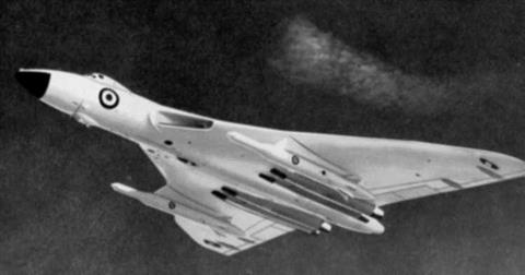
So work on a British nuclear device began very soon after the war. Soon Britain would have a working device. But there was the problem common to all three powers as to how the Bomb would be delivered. In the early post-war period, there was no alternative to the bomber, and the UK had produced some excellent jet bomber designs in the V bombers – the Valiant, Victor and Vulcan, which were to give sterling service to the UK for many years. Indeed, the Operational Requirement was issued at the end of the war, and nearly 40 years later, Vulcans were used in the Falklands conflict in the bombing role, with Victors in the tanker role.

It was realised in the early 1950s that with the increase in sophistication of missile defences, the V bombers, or bombers in general, would be increasingly vulnerable. Certainly it was expected that the likes of Moscow and other major cities would be surrounded by rings of guided weapons that could take out all but the most major bombing offensive – hence the issue of Operational Requirement OR 1132 in September 1954 for a stand-off missile, which would become Blue Steel. In 1954, the principal problem for such weapons was guidance over a long distance of flight (accuracy decreases with time of flight), and with that in mind, Blue Steel was designed with an operational range of 100 nautical miles. This would keep the bomber clear of Moscow and its attendant defences, although still leaving them with a large amount of hostile territory to cross.

At the same time, the Americans were working on various air-breathing long – range missiles, precursors of the later cruise missile. Ballistic missiles were being worked on by von Braun’s team, and by Convair under Brossart, but neither technology had advanced sufficiently to produce an effective weapons system that could deliver a nuclear device over a range of some thousands of miles. In

1954, Duncan Sandys of the UK and Charles Wilson of the US signed an agreement to share information on the development of ballistic missiles. By

1955, technology, particularly in guidance, had advanced far enough for serious design work to begin on a UK ballistic missile, Blue Streak, with a range sufficient to reach Moscow (the criterion for any UK nuclear delivery system) and beyond. At the same time, a parallel programme, called Black Knight, was also started to carry out some of the basic research, particularly on re-entry vehicles. And America began work on a much longer range missile, Atlas.

At that time, thermonuclear warheads were much more massive than they would subsequently become, and so all the early missiles designed by the US, by the USSR, and by the UK turned out to be far larger than was in the end necessary. This was to have important consequences as far as the Soviet Union and Sputnik were concerned. The enormous ballistic missile that had been developed by the Russians turned out to be much more effective as a satellite launcher. Neither the UK nor the US had designed anything quite as big as the Russian R-7, or Semiorka. Western politicians, often technically ignorant themselves and with axes to grind, assumed that these immensely powerful Russian boosters meant the Russians were that much further ahead in technology. In effect the reverse was true. The West had not built such large rockets because they were not necessary once lighter warheads had been developed.

Height/ft

Mass/lb

Thrust/lb

Semiorka R-7

98

588,000

874,000

Atlas E

92

260,000

385,000

Blue Streak*

~70*

198,000

270,000*

Thor

65

110,000

150000

* In its probable configuration if it had been deployed operationally.

All the early Western missiles such as Blue Streak, Thor, Atlas and Titan I, were designed to use kerosene and liquid oxygen as fuels, as did the first Soviet designs. Solid fuel rockets had not yet sufficient size or range given the weight of the warheads of the 1950s. (Minuteman and Polaris were designed assuming warheads would get lighter.) Such large rockets were also very vulnerable to a first strike attack, so would have to be stored in and fired from underground storage silos, hardened against nuclear attack. This added considerably to the expense of the system, and meant in addition that the missile and silo complex itself became a target.

All these missiles were close contemporaries in conception. Where they differed was that America and Russia pressed ahead with development despite the cost.

Development was carried on with Blue Streak as fast as funds allowed, although the whole project was bedevilled throughout its life by Treasury reluctance to release the necessary money. It could be said of the whole history of Blue Streak from 1955 to 1970 that the technical will was there, the political will was there intermittently, and the financial will was never there. It is astonishing how well the morale of those involved with the project stood up in the face of such political and financial uncertainty.

But in 1957 came the shock of Sputnik. The psychological effect on the Americans was considerable, and Atlas, among others, became a crash programme. In more than just the defence field, the US felt it had been overtaken. This led, among other things, to a massive effort in science and technical education. Its effect on British opinion was very much more muted. Britain did not see itself in any technological race, and was not perturbed by the thought of a satellite orbiting overhead. In the US, it was felt almost as an invasion of the country. Britain had suffered bombing of London as early as 1916, but the US had never experienced hostile aircraft in its skies. Sputnik was perceived in those terms.

Curiously enough, the Rand Corporation (and the RAE) had been undertaking studies into reconnaissance satellites, and had recognised that one legal problem might be that a satellite orbiting over another country may be taken as an invasion of the other country’s airspace. This is one of the reasons why the first planned US satellite was intended to be perceived as entirely civilian and part of the 1957 Geophysical Year. Sputnik had resolved this problem at a stroke. The Russians were in no position now to claim invasion of their airspace by American reconnaissance satellites.

Back in the UK, by 1958 the Black Knight rocket programme, intended to provide a lot of the basic research for Blue Streak, was up and running. It would yield a lot of useful information for the UK and the US on the physics of re-entry vehicles, necessary for any ballistic missile system, and also for studies into possible defences against them. The first flight of Blue Streak was planned for 1960, when the decision was taken by the Macmillan Government to cancel the system for military purposes. The reasons for this are complex and will be explored further in the Blue Streak chapters. In the same way that the USSR was eventually driven out of the arms race, so too was the UK, becoming increasingly reliant on the US for delivering its deterrent.

Mainly, I suspect, to minimise the political damage that ensued from the decision, it was announced that although Blue Streak had been cancelled as a weapons system, work would still continue, albeit at a much reduced rate, on developing a satellite launcher based on the missile. At least £60 million (all costs are given as of the period and not corrected for inflation), if not more, including large sums at Woomera by the Australians, had been spent on the project by this stage. A design, which would be known as Black Prince from the Saunders Roe brochure, or more inelegantly in official papers as the BSSLV (Blue Streak Satellite Launch Vehicle), had been under consideration for some time. It would have used Blue Streak as the first stage together with the proven technology of Black Knight as the second stage. Again, though, the major problem was money: one source mentioned that the development costs would amount to half the annual UK university budget, which even given the relatively small university sector in the UK at the time, gave pause for thought. And although the US military had found many uses for satellites, there was not the same perceived need by the UK military, particularly since British Intelligence had access to a good deal of the US information. Although the scientific community would have liked to launch various satellites (a stellar ultraviolet telescope was a favourite project), there were not the funds available in the civilian science research budget. Hence the UK was in danger of building a satellite launcher with no satellites to launch.

The decision was then taken to involve other nations in the project in the hope of sharing the costs. The Old Commonwealth countries were not interested, or lacked the finances and resources. France might be interested, but there was also the opportunity for France to acquire much needed data relevant to its own ballistic missile programme, which led to some difficulties and embarrassment. In the end, the European Launcher Development Organisation, ELDO, was born with little enthusiasm from many of its members. And the ELDO launcher ran into considerable criticism almost from the start, being widely perceived as unnecessary and based on obsolete technology.

The latter criticism was unfounded, although the much slower pace of development in the cash-strapped UK meant that the US tended to be there first. But Blue Streak remained irredeemably tarnished by its cancellation for military purposes. It had, however, the potential to be the equivalent of almost any American launcher until the Saturn vehicles. ELDO was both a political failure and a technical failure. Blue Streak itself performed almost flawlessly, but the same could not be said of the French and German upper stages. One of the reasons for this problem was that the other European countries were a good deal less experienced than Britain; another was that putting together a vehicle designed and built by three different teams of engineers in three different countries, speaking three different languages, was no mean feat. ELDO and its launcher died, never to be resurrected.

And what of the other project, Black Knight? After 22 successful firings, the project was declared at an end. But while the UK was still a member of ELDO, a decision was taken to proceed with an alternative, much smaller satellite launcher, and this would be based on Black Knight. The new design was called Black Arrow.

Two test vehicles were flown, one successful and one not, and then an orbital attempt failed by a small margin. On 29 July 1971, the announcement was made that Black Arrow was cancelled. However, the fourth vehicle was subsequently fired and achieved orbit on 28 October 1971, and that, effectively, was the end of rocketry in the UK. Skylark launches would continue for another 34 years, but there was little further development of the vehicle.

Space science has continued, and the UK has always been successful at building satellites. Indeed, Surrey Satellite Technology Ltd (SSTL) has been one of the major success stories of the past decade. It is also perhaps an exemplar of what the Treasury was maintaining – that if there is money to be made in space, then let private business get on with it.

Project Names

In the 1950s, the fashion in the UK was to give many of the military projects two word code names, the first of which was a colour: thus Orange Herald, Blue Streak, Yellow Sun, Red Duster, Violet Club, Green Flax and so on. A good code name should reveal nothing about the nature of the project. However, Yellow Sun for an H bomb was a bit of a giveaway, since the sun is a gigantic fusion reactor (or perhaps not: Mark 1 was not what is commonly understood by a ‘hydrogen bomb’, so perhaps there was an element of double bluff).

The rocketry projects covered in this book are Blue Steel, Blue Streak, Black Knight, Black Prince, Black Arrow and the various rocket interceptors. The ‘Black’ designations were applied, albeit unofficially, to research projects without a direct military application; indeed, Black Arrow was entirely civilian, but was named by extension from Black Knight, as probably was Black Prince.

The Rocket Propulsion Establishment (RPE) at Westcott, Buckinghamshire, produced many solid fuel rocket motors. A Superintendent who had been in charge of the Establishment had been a keen ornithologist, and so all the motors produced there were named after birds: Raven, Rook, Cuckoo, Waxwing etc.

Turbopumps or Pressure Feed

The pressure inside a combustion chamber can be very high – typically 500 psi or 33 bar. In the vacuum of space, a lower pressure can be used, but the efficiency of any rocket motor is reduced if used in the atmosphere, and one way of increasing the efficiency is by using as high a chamber pressure as possible. The question then is how to feed a large quantity of fuel into the chamber at such high pressure.

There are two options: a pump, or by pressurising the fuel tanks.

Pressurising the tanks had one big drawback: the tank walls had to be strong enough to withstand the pressure, which implies they are also going to be heavy.

The tanks can be pressurised from separate gas bottles, but, for large tanks at high pressure, that has a considerable weight penalty: the gas bottles themselves will be thick-walled and thus heavy. The alternative is a gas generator – two chemicals being mixed to produce large volumes of gas. The French stage of Europa used a gas generator; the German third stage was pressurised by helium in gas bottles. The great advantage of the system is that it is extremely simple and so there is little to go wrong.

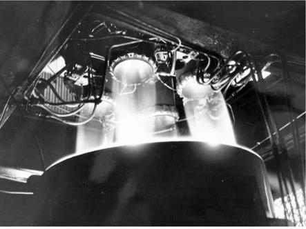
A pump has to be driven by something – there needs to be a turbine which is normally driven by fuel from the main tanks. In HTP motors, the kerosene and HTP were well suited to the purpose; the RZ 2 motors in Blue Streak had a turbine which used an excess of kerosene – that is, it burned fuel rich – to keep the temperature down. This can be seen very clearly in Blue Streak launches: the turbines produce bright yellow flames as a result of the excess of carbon.

The great advantage of pump versus pressure is that with a pump, the tanks can be as thin-walled as structurally possible (Atlas and Blue Streak took this rather to extremes). Some small pressure is still needed in the tank for the pump to function, but it is relatively small. One drawback is the extra weight of the turbine and pumps. Another is that the system is relatively complex, and provides another opportunity for something to go wrong.

One of the major problems, particularly with regard to the higher thrust engines, was producing pumps powerful enough to cope with the quantity of propellant at the high pressures needed, as this chart shows:

Flow rate (fuel + oxidant) Combustion chamber pressure

(lb/second)

(lbf/in2)

Snarler

10

300

Screamer

24

600

Beta

14

320

Gamma 1

39

450

Delta 1

205

500

RZ 2

560

525

The Missile Design

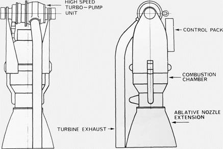
The rocket structure, like Ancient Gaul, could be thought of in three parts: the engine bay at the bottom, the main tank structure containing all the fuel in the missile, and the ancillary equipment, guidance and payload at the top. The engine bay, containing two RZ 2 motors, was 9 ft in diameter (so designed for transport by air), but the elegance of the final shape of the missile was rather spoiled by two panniers either side containing nitrogen to pressurise the kerosene tank. The liquid oxygen tank could be pressurised by oxygen gas derived from the liquid via heat exchangers. So in June 1957, de Havilland stated that

the propellant tanks, constructed of 0.019 inch thick stainless steel, remained unaltered. External stringers on the rear (kerosene) tank would permit the weight of the head to be supported without pressuring the rear tank. This would in turn allow the kerosene to be drained from the missile in the event of a failure occurring on the launcher.18

The upper tank had to be kept pressurised at all times to prevent the structure collapsing under its own weight. These 48 stringers also helped to give Blue Streak its distinctive appearance. Inside the fuel tanks were various baffles to prevent the sloshing of fuel, but missiles such as Blue Streak are not much more than gigantic thin-walled tanks.

For Atlas, skin gauges varied throughout the structure, being tailored to meet local stresses. The heaviest skin gauge was forty thousandths of an inch. By comparison, the skin gauge for Blue Streak was nineteen thousandths, but the lower section, the kerosene tank, was re-inforced with stringers. Blue Streak was simpler in being a pure cylinder, whereas the Atlas tanks tapered at the top. The most probable cause of the failure of such a structure in compression is what is known as Euler buckling – the process that occurs when you step onto an empty soft drinks can. But there were other reasons for the reinforcements.

A structure such as Blue Streak or Atlas is also very vulnerable to sideways bending forces, particularly when transmitting large loads vertically. These can originate from sideways gusts of winds, and also from the act of swivelling the rocket motors off centre for control purposes. Indeed, the two motors were to be inclined inwards slightly so that their thrust lines passed through the centre of gravity of the missile. Another problem to which liquid fuel rockets are prone is ‘sloshing’ which occurs when the liquid sloshes from side to side in the tanks as the vehicle rocks. Although it is often said that Blue Streak performed impeccably for ELDO in the 1960s and 1970s, this is not quite true. Sloshing of the fuel towards the very end of the first flight, F1, on 5 June 1964, overcame the control system and caused the missile to tumble uncontrollably.

The most important parameter for a ballistic rocket using no aerodynamic lift forces is the engine thrust. Two of the RZ 2 motors (see Figure 39) gave a thrust of 270,000 lb. Given that the smallest practicable initial acceleration is 0.3 g (and there is a good case to make this bigger in a missile) then the lift-off weight is of the order of 200,000 lb. Some of this, perhaps 4,000 lb, is payload. The rest is divided between fuel and structure, so that structure plus fuel amounts to 196,000 lb. Given 10% as structure, as an arbitrary figure, then this gives fuel weight as around 175,000 lb. Given the densities of the fuels, their volumes can be calculated. Given a diameter for the rocket – say 10 ft – then the length of the tanks can be estimated. Using these ‘back of the envelope’ calculations, then the outline of Blue Streak is quite easily arrived at. For comparison, the F1 vehicle with a dummy load of a ton, had a lift off mass of 205,000 lb, 190,000 lb of which was fuel. Detailed design is, of course, another matter.

Some of the design details were more obvious than others – for example, the tanks needed pressurising. For the oxygen tank this was simple enough: a small amount of the liquid can be vapourised in a heat exchanger and piped up to the tank. Pressurising the kerosene tank with oxygen gas would not have been a good idea: instead, nitrogen gas was used, being stored in spherical bottles in panniers either side of the engine bay.

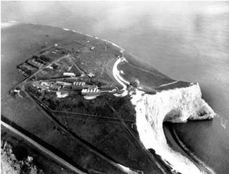
Whilst the tank section was to be built and tested at de Havilland’s site at Hatfield, testing the rocket motors was another matter. A purpose-built site would be needed for engine development and also for static firing of the complete vehicle. Not only would this be extremely noisy, it was potentially quite hazardous given the amount of combustible fuel contained within Blue Streak’s tanks. The site chosen was Spadeadam on the moors near Carlisle.

The Missile Design

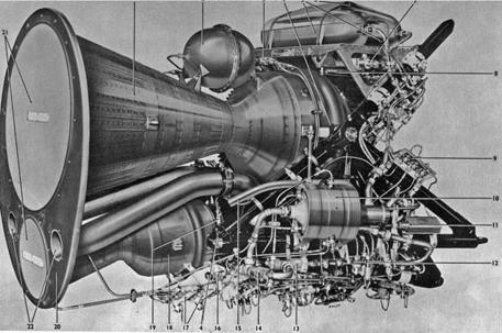
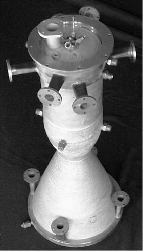
Figure 39. The Rolls Royce RZ 2 rocket motors that powered Blue Streak.

The Treasury was of course concerned with the cost: an estimate of £10.2 million for the construction of the Spadeadam site in April 1956 had become £12.3 million by October (and the final cost would be much higher). There is an interesting comment in a slightly later memo:

If a decision were taken to stop work on the MRBM… there would be a saving of some £70m. or more over the next ten years.19

If only the total cost had come to a mere £70 million! The decision to go ahead with Blue Streak was not yet firm at this time, and a further memo noted:

… it is probable that in the Policy Review a choice may have to be made between the supersonic bomber and the MRBM as research and development projects. The cost of R. and D. for the supersonic bomber would be about £70 million over the next 10 years – roughly the same figures as those for the MRBM, but the costs of producing and maintaining an appropriate number of supersonic bombers . would probably be higher than the costs of an appropriate number of MRBMs.20

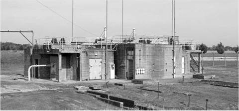
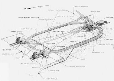
Spadeadam was split into five areas: the Administration area; the liquid oxygen factory, which was owned and run by the British Oxygen Company; the Component Test Area situated at Rushy Knowe; the Engine Test Area at Prior Lancy; and the Rocket Test Area situated at Greymare Hill.

The site is described in a Ministry of Aviation paper of November 1961 (the English is slightly eccentric at times):

The Spadeadam Rocket Establishment was built by the Ministry of Works on behalf of the Ministry of Aviation for the purpose of developing and the static testing of the British Ballistic Missile ‘Blue Streak’.

The Establishment is situated on the Cumberland Fells about twenty miles North-east of Carlisle and covers an area of approximately 8,000 acres. It comprises five main areas, three of which are test areas for the static testing of the complete missile, propulsion units and of the rocket engine component parts respectively.

As a safety measure these areas are separated by distances of up to one and three-quarter miles. This dispersion has required the construction of six miles of road connecting the ‘Areas’ on the Establishment.

MISSILE TEST AREA

This Test Area comprises two missile stands each with a traversing servicing tower on which the missiles are statically tested including the firing of the propulsion units.

By means of the gantry incorporated in the servicing tower, the missile is erected into the vertical firing position on the concrete emplacement situated at the end of a 300-ft concrete causeway.

Built into the emplacement is a steel flame deflector weighing nearly seventy tons for deflecting to the horizontal plane the jets of the rocket motors.

The large quantity of water required to maintain the temperature of the flame deflectors at a safe temperature level is pumped to the test stands via 36" diameter pipelines supplied from a one-million gallon reservoir situated adjacent to the Missile Test Area.

The necessary liquid propellants and high pressure nitrogen gas used for pressurising are stored in this area.

The Missile tests are instrumentated and controlled remotely from a central block­house situated approximately 1000-ft. from the test stands (both of which stands will be evacuated when firing is taking place on either stand) built of reinforced concrete. The tests may be observed from the Control Block-house by means of periscopes and closed-circuit television. In addition to the recording of test data on magnetic tape, film records of the tests are made by cine-cameras situated at strategic points around the test stand.

The main Instrumentation System comprises 19 Control Consoles, 4 Checkout Consoles, (46 Chart-type Recorders) with a capacity of 285 channels and three types of magnetic tape recorders with a total of 32 Information Channels. The Control Centre and each test Stand are connected by over 3,500 wires.

ENGINE TEST AREA

This area, in which the individual propulsion units are test fired, consists of three engine test stands… spaced 250-ft apart. A fourth test stand is partially complete.

Each stand consists of a massive concrete and steel structure in which the liquid propellant rocket engines are mounted to fire vertically downwards into a water cooled flame deflector which deflects the flame into the horizontal plane. The propellants used are Kerosine for the fuel and liquid oxygen for the oxidant. The early engine produced and evaluated by R-R Ltd. developed 135,000-lb thrust.

The Missile Design

Figure 40. The picture above shows a flight model Blue Streak (note the painted spiral) on a test stand at Spadeadam. The vehicle would be assembled, filled with fuel, and static fired before being shipped out to Woomera in Australia for launch.

The quantity of water used for flame deflector cooling, storage facilities and transfer systems are similar to those provided in the Missile Test Area.

At a distance of 600-ft from the nearest Engine Test Stand is the Control Block­house constructed of 2-ft thick reinforced concrete. This building is equipped with 130 chart-type recording instruments, four 24-channel oscillographs and, when fully equipped, eight control consoles for the remote control of the test equipment and the rocket engine during test. A large number of chart recording instruments are needed to obtain the maximum amount of technical data during the short duration of the test.

An underground concrete duct, 7-ft square and 1,100-ft in length, inter-connects the test stands with the control room for the routing of approximately 8,000 instrumentation and control cables.

The test firings are also recorded by cine-cameras from various locations around the test stands, the cameras being controlled remotely from the control room. These filmed records in addition to the other test records are processed and analysed in the Establishment.

Improving Europa

The first geosynchronous communications satellite was Syncom 2, in July 1963 (since the orbit was inclined to the equator, it was not, strictly speaking, geostationary). The first geostationary communications satellite was Syncom 3, launched in August 1964, and used to transmit the 1964 Olympics in Tokyo to the United States.

It was the French who, as early as 1964, realised the limitations of Europa and proposed that it should be dropped in favour of a more powerful design. To be fair, the design had been put together without much of a rationale behind the overall concept other than to produce a satellite launcher, and there had been no clear idea of what satellites it might be launching. Although Europa might be able to put a respectable payload into low earth orbit, there was simply no demand in Europe for such a capability. On the other hand, the French were quick to see the possibilities in communications satellites (unlike the British, who remained sceptical for a long time). ELDO A’s capacity for geostationary orbit was minimal or non-existent.

The French Government’s proposal was to replace the planned upper stages of ELDO A with what were usually referred to as ‘high energy stages’ – in other words, liquid hydrogen. An ELDO review paper of 1964 shows the thinking behind these designs [translated from the original French by the author]:

By 1963, the Secretariat had requested proposals from the member states for the

design of launchers using upper stages with high energy propellants.

The feasibility studies were placed by the Secretariat in November 1963. They

consisted essentially of two types of launchers:

– a launcher ELDO-B whose design used as first stage the Blue Streak of the Initial Programme. This launcher should be able to place at least 2 tonnes in low orbit and, with an apogee motor, at least 500kg in a synchronous orbit.

Подпись:a launcher ELDO-C which had been defined by its performance (6 to 10 tonnes in low orbit – 1.7 tonnes to escape velocity).

The reports corresponding to these studies have been studied by the Secretariat. Work complementary to these studies on these launchers has also been undertaken.

As a consequence, a general line of conduct can now be shown, which is based on the following principles:

1) using liquid hydrogen/oxygen gives advantages which can be seen from many points of view (high performance at a relatively modest cost, experience already acquired, function proved by launchers in the USA etc.)

2) an economic way of using this propulsion in different high energy stages by using one motor which can be grouped together and most importantly can follow the dimensions of the stages in question…

Whatever the choice of definitive designs for the launcher ELDO B, it appears that it is now possible to envisage beginning development work by the start of 1965.

This would involve. the development of a motor: it seems that a motor of thrust of 6 to 7 tonnes would be optimal… It is therefore the intention of the Secretariat to place in very general terms, within the body of the budget of the Future Programme 1964, three contracts for the study of such a motor; the development could begin, after the choice of the best design, at the start of 1965.6

One of the contracts issued was to Rolls Royce, who then developed the RZ 20 motor, intended for the upper stages of ELDO B.7

There were in effect two proposed designs which were closely linked: B1 and B2. The third design, ELDO C, was much sketchier.

B1 would have one upper stage, B2 would have two. Each of the stages would use the same rocket motor – as mentioned above, with a thrust of 6-7 tonnes (60-70 kN, or around 14,000 lb). By comparison, the American Centaur stage, first attempted launch 1962, had two motors each of 15,000 lb thrust. The B1 stage
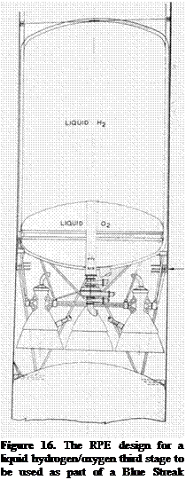
would have one of these motors, the B2 stage would have four such motors, and the B1 stage would be the third stage of the B2 design.

One problem was the large volume which liquid hydrogen occupies. This meant that the relatively light B1 stage was almost the same length of the first stage, and to assist aerodynamic stability at low speeds just after lift-off, it was proposed to fit four fins onto the kerosene tank of Blue Streak, although this idea only appears in early sketches for ELDO B. Another was that the maximum weight Blue Streak could carry in the form of upper stages was limited by the first stage thrust to 16,100 kg, and the extra weight on top of the vehicle meant that the stresses were greater so that thicker gauge stainless steel would be needed, making the first stage heavier.

ELDO B2 meant pushing Blue Streak to its limit – and perhaps beyond! The weight of the upper stages meant that the launcher would only be possible if the RZ 2 motor were uprated from 150,000 lb thrust to 165,000 lb, and the resultant vehicle would have a lift off acceleration of only 0.25 g. This implies a lift-off weight of the order of 265,000 lb. It would also mean strengthening the liquid oxygen tank by increasing the skin thickness from 0.6 mm to 1.5 mm, with a weight penalty of 0.85 tons. (Another solution was, of course, the strap-on boosters already described.)

The French failed to gather enough support from the other member states to switch the programme from Europa to ELDO B: at the Intergovernmental Conference in July 1966, a five-year revised programme for ELDO A and PAS vehicles was agreed; the B1 and B2 launchers were effectively abandoned at the same conference.

A little money was still available for ‘studies’. In the following years, different firms produced a plethora of designs for an ELDO B launcher, some not much more than sketches, others fully worked out designs, but as a consequence of the intransigence of the British Government, none of these were to come to fruition. However, they were to appear once again when studies began for a Europa III.

For a variety of reasons, opposition to ELDO B was led by the UK. Firstly, the new Wilson Government were against ELDO in itself; the last thing they and the Treasury wanted was an open-ended commitment to further spending. Secondly, it did not share the French view that the future lay in communications satellites, and moreover, even if it did, it was not convinced that there would be sufficient demand for a second, competing system. Thirdly, it did not believe that it would be ‘economic’ in the sense that the United States could always undercut ELDO in price. (There is a further discussion about this in the section about the Treasury.)

There was a fourth factor too: the UK had no inherent objection to using American launchers (the early military Skynet satellites were launched using Delta and Titan launchers, although later ones have used Ariane 4 and Ariane 5). The French, on the other hand, were very resistant to the idea of relying on the United States. In particular, they were wary of the restrictions that might be placed on competing commercial systems.

There was one other requirement if Europa was to be used to launch communications satellites: a new launch site. Firstly, whatever site was chosen would have to be as close to the equator as possible – unless the satellite is in an equatorial orbit, it will appear to ‘wander’ north and south in the sky. Secondly, communications satellites need to be launched in an easterly direction to take advantage of the spin of the Earth. The difference this makes is quite considerable: the speed of rotation of the Earth at the equator is close to half a kilometre a second. A clear launch corridor is also needed: the first stage of the satellite launcher will fall to the ground not that far from the launch site, and if the flight has to be terminated for any reason, or the launcher explodes, then the debris cannot be allowed to fall on populated areas. Woomera had very restricted launch corridors, which were mainly in a northerly direction. As a range for testing rockets and missiles, Woomera was ideal, but it had considerable geographical limitations as a satellite launching base.

Effectively then the site had to be on the eastern seaboard of a large ocean, where spent stages could fall without hazard (except to passing shipping!). ELDO considered several sites, although only two were serious contenders. One was the Australian proposal of Darwin in northern Australia, and the other was the French proposal of Kourou in French Guiana, an overseas region and departement of France located in South America. The choice fell on Kourou, which is now used for the Ariane launchers. Darwin was ruled out on various counts. One was that it was technically inadequate (this seems rather odd – the infrastructure at Kourou cannot have been very advanced at that stage), from the safety angle as being too heavily populated, and cost – which again seems a little odd. Woomera had cost ELDO nothing as it was being provided by the Australians, and it might well be expected that Australia would pay for a large part of the new site. One valid technical point was that it was further from the equator (12°S as opposed to 5°N).

The impression here and elsewhere is that the French are in the driving seat, and that choices were often made for political reasons, with technical reasons coming second (and the reasoning often questionable: would northern Australia be ‘technically inadequate’ compared with the South American jungle?). The new vehicle was given the title of Europa II, although the changes were fairly

Improving Europa

Figure 74. ‘Arcs of fire’ from Darwin and from Kourou.

minimal. The British objected to even this fairly modest proposal on the grounds that the PAS system was not part of the ‘original programme’. This was a mantra that the British Government would produce time and again.

Even so, 170 kg was not a particularly substantial payload for a communications satellite. To be of much use, this would have to be increased, and one cheap and easy way of doing this was to add strap-on boosters.

Indeed, as early as January 1963 the Italians came up with a proposal for 10 ft diameter solid fuel motors to be strapped on to Blue Streak, rather in the style of Titan III. The proposal was passed through to RAE, where Harold Robinson thought some of the assumptions rather optimistic.8 The Italians thought the combination could put 10 tons into orbit; Robinson was more pessimistic at 6.25 tons. Making motors this size with no prior experience would have been a considerable challenge, and in addition, Blue Streak would have to be strengthened quite considerably to take such a load.9

Since the French were now the leading lights in ELDO, it was inevitable that most of the proposals for uprating the launcher would come from them. Of the
many proposals made to improve Europa, the most significant from French companies such as SEREB (Societe pour l’Etude et la Realisation d’Engins Balistiques). One such proposal used P16 solid fuel boosters (P for French poudre, early solid fuel rockets being made from gunpowder) derived from the first stage of the French silo-based ballistic missile. The L17 liquid fuel boosters derived from the Diamant satellite launcher.

Figure 75. On the left is Europa with the French P16 boosters. Drawn on the right is the version with French L17 boosters.

Blue Streak

P16

L17

Diameter/m

3.1

1.5

1.4

Propellants/kg

88,500

16,440

33,500

Thrust/kN

1335

550[11]

668

Burn time/second

160

75

111

Total impulse/MNs

213

41 x 2 = 82

74 x 2 = 148

Payload[12]

170

300

290

Improving Europa

modern communications satellite. On the other hand, only two boosters are being considered. Ariane had a ‘pick and mix’ approach to boosters, with two or four solid or liquid boosters. Four boosters would certainly increase the payload a good deal further – and give the opportunity to stretch the upper stages at the same time.

Even larger boosters were being considered, as this talk by Dr K Iserland of ELDO in 1968, given to the Royal Aeronautical Society, shows:

… on the other hand, the use of liquid boosters is also being studied, and, in particular, two practical solutions – one based on Blue Streak, in other words using two Blue Streaks as additional boosters, and the other based on the technique of Diamant B, using the first stage of the improved version of the French Diamant B

Подпись: Figure 76. On the left: three Blue Streaks strapped together, and on the right, Blue Streak might weh have been to design with French Diamant strap on boosters. Both a bigger core - which is what versions have a liquid hydrogen upper stage. Europa III was all about. launcher… in the first case three Blue Streaks are attached together side by side and they would all be lit up together from the start. Propellant would be pumped continuously from the outer boosters to the engine of the central Blue Streak so that, at booster jettisoning, the central or core stage is still full and continues to burn for a full burning time. The version deriving from Diamant B type uses four boosters clustered around the central Blue Streak. They each have a diameter of 2.4 m, as compared with the 3 m of Blue Streak, and have 4 engines of 36 tonnes thrust each. The outer four boosters are functioning as a zero stage… i. e., the core stage is lit up at the end of the booster phase only.

It might be said that having to resort to these rather extreme measures points up the inadequacy of Blue Streak as the main core. A better approach

In December 1969, an ELDO report outlined various feasibility studies for a Europa III design10. It was stipulated that the new vehicle should have the capacity to launch 400-700 kg into geostationary orbit, and a brief history of previous proposals was outlined – the most significant of which had been made in 1969, when there was a proposal to replace Blue Streak with a French designed first stage designated the L135, which burned N2O4/UDMH. It would have a diameter greater than 3 m and the capacity to put a payload of 600 kg into geostationary orbit.

The report also thought that the proposal to uprate Europa II with boosters for relatively low cost to give around a 280 kg geostationary payload would not meet the payload criterion. A new booster would be needed, and four possibilities for the first stage were then considered (in the context of this discussion, ‘high energy’ can be read to mean ‘liquid hydrogen’).

A: This would be based around Blue Streak with a high energy stage, which would have been capable of putting 500 kg into geostationary orbit. The problem was that this design lay at the lower end of the performance spectrum.

With strap-on boosters, the payload was increased to 750-800 kg, but there were two drawbacks: firstly, that the design had been stretched as far as it would go and so no further development was possible; and second, that the 3 m diameter of the stage was thought to be a disadvantage.

There was also the consideration of the availability of Blue Streak after 1976 given the British Government’s attitude to ELDO – although no doubt Rolls Royce and HSD could have produced them easily enough on a commercial basis. The running costs of Spadeadam might also have been a problem, since it was currently being funded by Britain.

B: this was based on the French L135 design already mentioned, with a diameter of 3.6 m, and a capability of launching 700-750 kg to geostationary orbit.

C: the first stage would have been powered by four RZ 2 chambers, downrated back to 137,000 lb (it is not made clear why the downrating was thought to have been a good idea). It was thought that this vehicle was capable of 850-900kg to geostationary orbit. The report shows a distinct lack of enthusiasm for the design, with the comment that Europe was ‘more experienced in N2O4/UDMH technology than in lox/kerosene’. This is an odd comment, since liquid oxygen/kerosene is hardly the most sophisticated of technologies, and the motors were to be provided by Rolls Royce, which did have a fair amount of experience in the technology. It was probably the political dimension which ruled this design out – the main motors for the vehicle would have been produced in a country which was not a member, and which had done its best to wreck the organisation! The tank structure would have been light alloy rather than the stainless steel balloon design of Blue Streak.

The timescale for each of these three designs would be set by the high energy upper stage – that is, the liquid hydrogen upper stage.

D: this was an all hydrogen design, which looked distinctly aspirational – in other words, whereas engineers might relish the challenge of producing such a design; politically and economically it represented a distinct challenge.

The estimated cost of each design (in MMU) was:

A

B

C

D

641*

770

747

852

629**

* with solid boosters

** with liquid boosters

MMU = Million Monetary Units, the notional currency of ELDO, effectively equivalent to one American dollar. 1 MU = £0.413

On the other hand, given the speculative nature of most of these designs, any attempt to cost them seems distinctly futile. They are probably in the right order, but that is about as much as can be said for them..

The conclusion of the report ran roughly as follows. Option A was viable only if cost were a consideration. B represents the best compromise – although, again, it was not made clear what the compromise was. C matched the performance criterion but ‘represents from the engineering standpoint a compromise with the EUROPA I and II vehicle system’. This is another fairly political point, since the only part of Europa that had worked without fault on every flight was the RZ 2 motor, and that was the only point of commonality. As for D – it was acknowledged that the design was not very realistic at the present time.

Despite these figures, the report of EUROPA II AD HOC group in May 1972 came to very different conclusions. (The ‘low cost configurations’ being referred to are upgrades of Europa, or option A in the previous report.)

The EUROPA II ad hoc group concludes that, even without making provision for additional development launchings, the low cost configurations will most probably not result in a significant saving with respect to EUROPA II; if provision is made for additional firings – the necessity of which is accepted, except by the German delegation – all low cost launchers will be more expensive than EUROPA III.

Improving Europa

The ad hoc group notes that the low cost launchers do not have the same growth potential as the EUROPA III launcher whose performance increase would be more cost effective.

Under the circumstances, the majority of the EUROPA II ad hoc group cannot recommend further study of the so-called low cost configurations.11

Whether or not Blue Streak-based options were technically adequate or financially viable, there is a very strong likelihood that they would be politically unacceptable, given the past attitude of the UK Government.

As is well known, option B was chosen, and after further evolution of the design, went on to become Ariane I – but that is another story.

More interesting from the British point of view was option C. Unlike Blue Streak, it would have light alloy tanks rather than stainless steel, but still with stringers to the kerosene tank (it was not made clear why stringers would be needed with conventional tanks). The main stage motor would have four RZ 2 Mk III engines each of 62.2 tonnes (137,000 lb) thrust, with the ability to swivel in the tangential plane only (this feature might have been borrowed from the Gamma 201 of Black Knight). Quite why the thrust had been down rated from

150,0 lb back to the original 137,000 lb was also not made clear.

The estimated cost of the new motor was £7,536,500 (18.1 MMU), and the annual cost of running Spadeadam was put at 2.25 MMU. There would be a completely open engine bay, 3.6 m diameter, with each motor having a separate pump and turbine.12

Val Cleaver of Rolls Royce produced the brochure, which he sent with a covering letter. The letter did not display a great deal of enthusiasm for the proposition, describing the RZ 2 as ‘1950s technology’, and hinting strongly that a motor using high energy propellants would be far more interesting. Cleaver might have been a good engineer, but he was obviously not so good as a salesman! Whatever his feelings about being asked to produce a design of that sort, he might have done better to keep them to himself.

The ironic part of the story is that a four engined RZ 2 first stage would have almost certainly have been cheaper to develop than the L135 design which became Ariane and would have kept the UK in the launcher business. With any luck, it could have been as successful as Ariane was. Unfortunately, the British Government was actively hostile to the idea of a new launcher, and the new design was effectively a French vehicle. Thus ELDO died, and Ariane was born. [13] [14]

BK11

Single stage. Launched 17 October 1963. Apogee 322 miles.

This was launched in support of the ELDO programme, and was designed to test the safety systems and the broadband telemetry. The interim report issued after the flight had this to say:

Two WREBUS [Weapons Research Establishment Break Up System] command destruct systems were tested with a comprehensive programme during the whole of the flight. One WREBUS system was commanded by a transmitter located at Red Lake, and the other by a temporary low-power installation at the rangehead. The test programme featured both manual and automatic command functions.

… During the whole of the flight the broadband telemetry system… functioned well and records of equipment monitoring were obtained.4

A second vehicle, BK10, was in reserve in case the tests had to be repeated. Since the flight had met all its objectives, BK10 was never fired and is now in the World Museum, Liverpool.

BK11

BK11

Figure 99. The re-entry heads of Project Dazzle.


Подпись:The final six Black Knight launches were part of Project Dazzle, and the various re-entry heads can be seen in Figure 99 above. The range instrumentation was greatly improved, as can be seen in the pictures above.5 The purpose of these flights was to study re­entry phenomena more closely. Dazzle was a joint UK/US/Australian project – the UK providing the vehicles and re-entry heads, Australia supplying the range facilities, and the US supplying much of the instrumentation.

A Black Knight IRBM

One rather unusual proposal surfaced at the time when Skybolt was cancelled. At the subsequent Nassau conference in December 1962, Macmillan was able to persuade President Kennedy to provide Polaris, effectively without strings. This seemed to be distinctly improbable at the outset, and there was obviously a short period of almost panic in the British delegation. Without Skybolt and without Polaris, Britain would have been thrown back entirely on its own resources, which were then very few. Sir James Lighthill, at that time Director of RAE, came up with a proposal for a missile based on Black Knight and wrote a note for Macmillan headed ‘A Possible British Deterrent’. It begins by saying:

Advances in technology make it possible, today, to do Blue Streak’s job with a rocket at one tenth of Blue Streak’s weight. The main advances have been in reduction of weight of warhead, and the perfection of the technique of the two-stage rocket, whose first stage is shed after it has burnt itself out.1

He then put forward the idea that:

… The very successful research vehicle BLACK KNIGHT (an entirely British development began in 1956 as a ‘lead into’ BLUE STREAK and first fired 2U years later) could now do the job with a small second stage. Several two stage rockets with BLACK KNIGHT as first stage have actually been fired. In the last three firings, all systems (including first and second stage separation, and complex data processing and transmission systems) worked as planned. In all fourteen firings of BLACK KNIGHT, the first stage flew successfully.

For delivery of nuclear warheads over 1500 nautical miles (the London Moscow distance), a suitable second stage would be one using the extremely well tried Gamma 201 engine (of 4000 pound thrust). Guidance would be based on the Ferranti miniature stable platform, of which the prototype has already been satisfactorily tested.

The fuels would be kerosene and hydrogen peroxide (which can be stored at room temperature for a whole month). The missiles can be fired from small hardened sites (a tenth of the size contemplated for BLUE STREAK), and would be vulnerable to a megaton explosion only if it took place less than half a mile away.

The system suggested would use proven components that started development in 1956. It would probably reach the first flight after two years of further development (at high priority), and begin to come into service after another two years (and some 30 test flights).

A tentative estimate of research and development cost includes £15m. spent on the missiles plus £20m. on the Woomera range, which I add together around up to £50m. The cost of operational missiles and launch sites is estimated at £200,000 and £500,000 respectively, which I add together around up to £1m. per missile. These figures suggest that for £100m. (essentially what remains to be spent by us on SKYBOLT) we could have 50 of these rockets. (They would be simpler and cheaper than the US rocket Minuteman because of the much shorter range required).2

In the end, Britain did acquire Polaris without strings, but Lighthill’s suggestion was probably the most viable if Britain wanted to retain its deterrent yet ‘go it alone’. Certainly some form of Black Knight would be the only ballistic missile which could have been developed in less than five or six years, and by far the cheapest.

Obviously RAE followed up this idea later, when the dust had settled:

An investigation was recently made into the possible use of Black Knight as an IRBM Two cases were considered, both based on the 54" Black Knight with a sea level thrust of 25,000 lb weight. The first assumes that HTP and kerosene were the propellants, with a vacuum specific impulse of 250 secs; the second that the specific impulse can be raised to 280 secs by using propellants such as NTO/UDMH. In both cases the second stage used the same propellants as the first stage. The maximum range of an 800 lb re-entry vehicle was found to be just over 1000 n. miles with the HTP/kerosene combination and 1500 n. miles with NTO/UDMH.3

And later in the report: ‘It was found that a second stage weight of 3500 lb at a thrust of 6000 lb was about the optimum.’

Changing fuels would have negated one of the major advantages of the proposal: it was simple, cheap and made use of existing and proven hardware.

It is curious that a much more useful proposal was not pressed into service at this point. The 1958 proposal for an IRBM from Armstrong Siddeley, resurrected in 1960 (described in the Black Arrow chapter), would have been eminently suitable. The design is basically a much enlarged Black Knight, but instead of the small Gamma engine (4,000 lb thrust), it uses the large Stentor chamber: 24,000 lb thrust. Thus the proposed vehicle is six times more massive. It would have been easy enough to put a small second stage on top, and it would certainly have had the range to reach Moscow.

As an alternative missile to Blue Streak, it had the advantage that the propellants are storable, or reasonably so. Certainly, HTP would be easier to handle than liquid oxygen within a silo, and could be stored in the missile for long periods – months rather than weeks.

Certainly, an alternative history or counter-factual for Nassau would be interesting: what would Macmillan have done if Polaris was not available, or at least hampered by a sufficient number of strings as to make it political unpalatable? The only possibilities were some sort of air-launched missile (a ramjet cruise missile, the X-12 or Pandora, was being suggested at the time), or (with a large number of people having to eat quite a few words) a land-based missile, and here a Black Knight derivative is an obvious choice. Like Titan II and unlike Blue Streak, the fuels were storable in the missile, making for a much more credible weapon.

It is interesting, although coincidental, that such a missile would have looked very much like Black Arrow, whose development costs were a mere £10 million. The first flight of Black Arrow was in June 1968, and, given proper funding, this could have been reduced by at least two years or more. Lighthill had noted that it was now possible ‘to do Blue Streak’s job with a rocket at one tenth of Blue Streak’s weight’. That was perhaps a touch optimistic, but Black Arrow at 40,000 lb was actually a fifth of the weight of Blue Streak’s 200,000 lb.

Rocket Fuels

Liquid fuel rockets need a fuel and an oxidant. The UK used kerosene as a fuel almost exclusively, although a lot of work was done on liquid hydrogen, but sadly no use was made of this work. HTP (High Test Peroxide) was the most common oxidant: this was an 85% solution of hydrogen peroxide (H2O2) in water. The hydrogen peroxide decomposes to steam and oxygen on a catalyst (silver mesh gauze) and kerosene injected into the resultant hot gases ignited spontaneously. However, Blue Streak used engines (see Figure 1 below) licensed from the US and re-engineered, which burned oxygen and kerosene. The measure of the effectiveness of a rocket motor or fuel combination is called Specific Impulse. This was always written in documents of the period as S. I., but nowadays is usually written as Isp. This can be defined in many different ways: one is thrust times burn time divided by mass of fuel burnt. Another way of looking at it is the thrust obtained from each pound of fuel burned per second. The HTP/kerosene combination had a relatively low S. I., around 210-220 at sea level. Oxygen/kerosene gives an S. I. of around 245 at sea level. The effectiveness of a rocket motor is increased at high altitude or in vacuum. This is because the thrust from a rocket engine derives from the pressure difference between the pressure inside the combustion chamber and the pressure outside. In a vacuum there is no outside pressure. Thus S. I. is sometimes quoted at sea level and sometimes in vacuum. Vacuum S. I. is typically 10-15% higher than sea level. Hydrogen/oxygen is the most effective combination of all, reaching S. I.s of at least 400. This means double the thrust for the same weight of fuel (and burn time). Against that, there are weight penalties in the use of liquid hydrogen, since it has a very low density and needs large tanks. It is also very cold, boiling at -253 °C or 20 K, so the tanks usually need extra insulation, which in turn implies a further weight penalty.

Rocket Fuels

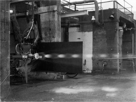
Figure 1. Rolls Royce RZ 2 rocket motors in a test stand at Spadeadam.

Cooling

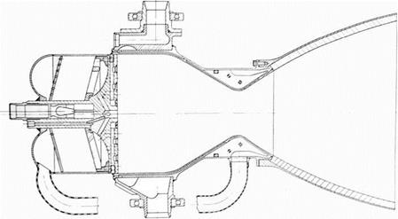
Rocket chambers will, not surprisingly, get very hot, and ways have to be found to stop them getting too hot. One method is to use film cooling. At the top of the chamber is an injector, where the fuel and oxidant enter the chamber, and it usually resembles a shower head. It is designed so that the fuel and oxidant can mix and burn as quickly as possible. In film cooling, the injector feeds in only fuel at the very edge of the chamber, so that the sides of the chamber wall will be in contact with relatively cool unburnt gas. This usually means a slightly reduced efficiency, as the motor is running fuel rich. The next and most obvious method is to use the incoming fuel to cool the chamber walls before being injected into the chamber. This is called regenerative cooling. One way to do this is to have a double walled chamber, with the fuel flowing between the two walls. This tends to be rather heavy – the pressure in the chamber is obviously quite high, and so the walls need to be robust. This is illustrated in the de Havilland Spectre motor shown in Figure 6.

A refinement on this method was to make a chamber of thin nickel tubes brazed together. Reinforcing bands were usually attached around the tubes, but overall, the construction was much lighter. This technique was first used in the RZ 2 motor for Blue Streak and the chambers of the Stentor motor for the Blue Steel missile. Fuel or oxidant then flows through the tubes to cool the chamber.

Sometimes the expansion cone for upper stages is left as plain metal, and this is sometimes referred to as ‘radiation cooling’ – in other words, the metal is left to glow red hot and literally radiates its heat away into the vacuum of space.

Cooling

Figure 5. A double walled chamber. In this de Havilland Spectre motor, HTP is used as the coolant.

Cooling

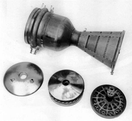
Figure 6. A sectioned example of a liquid hydrogen chamber made at RPE. It has been fabricated from a series of nickel tubes pressed into shape and brazed together. Fuel would flow through the tubes as a coolant.

Lubbock and his co-workers at the Fuel Oil Technical Laboratory in Fulham, London, were the first in the UK to work on liquid fuelled rocket motors. Their first design, called Lizzie, was fuelled by LOX (liquid oxygen) and petrol. It was a very simple device: the propellants were forced into the combustion chamber using high pressure nitrogen, so no pumps and other ancillary equipment were needed. It was intended for rocket assisted take-off in aircraft such as the Wellington. In 1946 it was the first liquid fuelled rocket motor to be test fired at the RPD Westcott, and was eventually developed to give thrusts of up to 2000 lb.

Подпись: Figure 7. ‘Lizzie in a test shed at Westcott. Lizzie was used to power the Liquid Oxygen Petrol/

Guided Aerial Projectile, or LOP/GAP, which was an

early test vehicle, fired from

Aberporth in Wales, and later, the Rocket Test Vehicle 1 or RTV-1. Problems cooling the engine led to a change of fuel to a methanol/water mixture. As a consequence of work with Lizzie, it was realised that hydrocarbons did not act as good coolants for rocket engines, and that their flame temperatures are also relatively high, exacerbating the cooling problem. Kerosene was not considered again for rocket motors in Britain for some years.

LIQUID OXYGEN MANUFACTURING PLANT

To provide for the large consumption of liquid oxygen, a manufacturing plant has been constructed at Spadeadam. The plant is capable of producing a total of approx. 100-tons of liquid oxygen per 24-day in addition to liquid and gaseous nitrogen. The liquid oxygen is transported by road tankers from the plant to the storage tanks in the test areas, the nitrogen gas is pumped by pipeline to high pressure reservoirs in each of the areas.21

LIQUID OXYGEN MANUFACTURING PLANT

Figure 41. Rocket test stands at Spadeadam.

Spadeadam was built by the Ministry of Works under the supervision of the Ministry of Supply. It was one of the few areas of the whole MRBM programme over which the Treasury had direct control. (It was probably also the most expensive – the estimate of the cost at the time of cancellation was around £24 million). They kept spending under a tight rein, an example of this being when PFG Twinn of the Ministry of Supply wrote to the Treasury asking to be able to spend up to £10,000 on particular items without seeking direct Treasury authorisation. Reluctantly, the Treasury agreed.

Spadeadam was obviously extremely remote, which is why it was chosen in the first place. This did lead to transport difficulties, particularly when showing visitors round. Twinn requested authorisation for some transport in the form of:

1 Ford Consul Black with Heater Saloon 4-6 seats £556

1 Ford Prefect ditto ditto 4 seats £42422

To which the Treasury replied:

We approve the purchase of the Ford Consul, but would be grateful if you would substitute a Ford Popular for the proposed Ford Prefect. Hundreds of Populars are in use in Government service, and we would rather keep to this cheaper 4-seater model.

It really is quite extraordinary that the ministries should be debating the relative merits of a Ford Prefect or a Ford Popular. One cannot quite see the same problem arising at Cape Canaveral.

In July 1959, an official from the Treasury, Mr JA Marshall, set off to inspect Spadeadam in the company of Mr William Downey from the Ministry of Supply. ‘The visit was enjoyable (in spite of almost continual rain) and instructive,’23 he remarked.

In general, he approved: ‘The administrative block is a modest and simple construction as far as I saw it, and there certainly appears to be nothing lavish here.’

But later he was to observe one example of:

… what I would regard as some extravagance.

This is in the housing of the lines which run from the control and recording centre to each of the four stands. It has been put wholly underground. in a tunnel some 400 yards along.

Other cables had been put in an over ground duct. Mr Marshall enquired why this had not been done here. He was told: ‘. had it not been so placed, it would have obscured the view of those in the control centre’.

It also had to be carried under a road, but Mr Armstrong was not entirely convinced it had been necessary to put the entire length of cable underground.

Despite this particular example of ‘extravagance’, Mr Marshall seemed satisfied with his visit. He was ‘well impressed by all I saw’, which included the control rooms, full of:

electronic instrumentation provided to record every possible facet of the test for subsequent analysis. To the layman this produces a hopelessly bewildering mass of knobs, buttons, recording graphs, lights etc’

He goes on:

Mr. Downey had the courage to ask the schoolboy question: “Which is the button which actually sets it going?”. The scientist who was showing us round was utterly at a loss for about a quarter of a minute!

There were other problems. ‘Commander Williams, the senior Rolls Royce representative, who is the general manager of the place, had a go at me on two minor things’.

This related to the housing which had been built for those working at Spadeadam.

He said he thought the Treasury were unduly mean in not allowing them to build a higher proportion of garages… a number of people who have no garages… do have cars and keep them standing in the street… Since the streets are fairly narrow – the whole estate is on very modest lines – this could be a serious nuisance…

And also:

He also thought we underestimated the difficulties they faced when we insisted on a certain proportion of the houses having two bedrooms instead of allowing them to be all three, or in a small number of cases, four-bedroomed.

How much was the Treasury saving? Mr Marshall noted that ‘… the additional capital cost of the three bedroomed house is only £70 …’, but on the other hand, ‘we get an extra 5s. a week rent back from it’.

5s. means 5 shillings, or 25p in decimal money. The extra room would have paid for itself in just over five years.

If Blue Streak had gone ahead in its military guise, then a considerable number (no figure has been found, but a reasonable estimate might be between 10 and 20) of experimental and proving vehicles would be needed, as well as the 60 or so production missiles, starting in 1960 and ending by about 1966. Somewhat optimistically, the development schedule had called for the first missile to be fired from Woomera around mid-1960. As it was, the first vehicle was not fired until 1964, and there were a total of 11 firings by 1971 (in practice, more were built and tested, as there were some basic, non-flight, development vehicles, and also some which were used to check at the sites at Woomera and Kourou).

Thus after the cancellation, the tempo of work slowed considerably, and only one of the missile test stands, C3, was completed. There were also inevitable redundancies and a considerable drop in morale. In May 1967, Val Cleaver, Chief Engineer of the Rocket Department at Rolls Royce, wrote of the need ‘to raise morale and inspire some confidence in the future of the establishment’24, but apart from the test site for the liquid hydrogen RZ 20 motor, no further development work was carried out at Spadeadam.

LIQUID OXYGEN MANUFACTURING PLANT

Figure 42. RZ 1 chamber on P site at RPE Westcott.

Spadeadam would take time to build, so whilst it was being constructed, Rolls Royce used the P stand at Westcott for preliminary testing of the Rocketdyne derived RZ 1. Most of the runs were of very short duration – usually just a few seconds. Progress was delayed by a spillage of liquid oxygen onto the steel girders, which caused them to crack. One of the longest test runs was also the last, on an open day at which the Press was present. A motor was fired for 20 seconds, and on being checked after the firing, it was found that the gear box between the turbines and the pumps had disintegrated. A fraction of a second more, and the firing might have become very spectacular.

So from mid-1957, testing and development proceeded apace. At Hatfield in

Hertfordshire, large structures were built to house the testing of early, non-flight vehicles. These were for checking the strength of the vehicle structure and for such tasks as determining whether half a ton of fuel could be pumped from the tanks each second. Engine testing was carried out separately by Rolls Royce, first at a test site at Westcott and then at the purpose-built facility at Spadeadam in Cumbria. Here, in addition to engine development, assembled vehicles could be static fired. Once tested, they would then be taken apart for transport to Woomera.

Transport proved to be a difficulty. The large size of the tanks meant that very few aircraft would be suitable, and those which were, such as the Bristol Freighter, had limited range. This meant a great many countries would be overflown on the route from the UK to the Antipodes, and, given the nature of the cargo, political difficulties were foreseen. The problem was solved when the RAAF bought Fockheed Hercules aircraft: one of these could be leased from Australia for the purpose. And given the extra range of the Hercules, the overflying problem could be reduced by going westward round the world, over Canada and the US. As it would turn out, the tank of the first missile was at Fos Angeles when the cancellation was announced, and it was returned to the UK. All subsequent civil vehicles were transported by road and sea.

Another of the major problems in the early development was that of guidance. The contract had been given to Sperry, but they were struggling: ‘… accuracies being demanded from the inertial equipment for this project are extremely high and very marginal. It does seem that these accuracies are just

Figure 43. Cutaway view about obtainable,..’25 in January 1956. There is a of Blue Streak. despairing cry from the Director of Air Navigation in

October 1956: ‘There does not yet exist, I believe, anywhere in the world a gyroscope suitable for Blue Streak.’26 This was not quite true: American gyroscopes were very much more advanced, and Ferranti was eventually given the job of adapting Kearfott gyroscopes for the guidance system. Although these were probably not the best the Americans had under development, they were perhaps the best they were prepared to make available to the UK. And in November 1956: ‘It will thus be seen that, though the Blue Steel situation is parlous, the Blue Streak position is even more desperate’. A working design was finally produced, although in the end it was never used: the guidance system was cancelled at the same time as the missile. A satellite launcher needed a much less complicated system, and scrapping the Blue Streak inertial guidance could save money.

As the 1960s progressed, inertial navigation was to become much improved: a system designed for the TSR 2 aircraft was adapted for Black Arrow. Blue Steel was left to soldier on with a much earlier design, which, with its valves, was very power hungry. Again, the penalty was being paid for being early in the field.

Подпись: Figure 44. An early test vehicle being lifted up into the stand at the de Havilland factory at Hatfield. But the next, and most controversial, point about Blue Streak was to be its proposed means of deployment. To have the missile sited on the ground in the open, as the Thor missiles were, was pointless. A pre­emptive strike by relatively few Russian missiles would have destroyed every site before a missile could be fired in retaliation. As all sides in the Cold War realised, land-based missiles would have to be sited in ‘invulnerable’ silos, although the word ‘silo’ was not in usage in the UK at that time. Indeed, the two phrases used became code phrases, showing which side of the controversy you were on. ‘Underground launcher’ was the phrase used by those in

Подпись: 11 12 TNA: PRO T 225/1775. Guided weapons development contracts: Blue Streak and Black Knight. 13 Ibid. 14 Ibid. 15 TNA: PRO T 225/1150. ‘Blue Streak’ medium range ballistic missile: Spadeadam test site. Memo by DR Serpell, 18 October 1956. 16 TNA: PRO T 225/1775. Guided weapons development contracts: Blue Streak and Black Knight. 17 TNA: PRO AVIA 65/714. Spadeadam engine testing: Rolls Royce Ltd. 18 TNA: PRO AIR 20/10299. Ballistic missiles: minutes of Joint US/UK Medium Range Ballistic Missile Advisory Committee and related papers. 19 TNA: PRO T 225/1150. ‘Blue Streak’ medium range ballistic missile: Spadeadam test site. Memo by DR Serpell, 30 October 1956. 20 Ibid. Memo by DR Serpell, 3 November 1956. 21 TNA: PRO AVIA 65/715. Spadeadam engine testing: Rolls Royce Ltd. 22 TNA: PRO T 225/1150. ‘Blue Streak’ medium range ballistic missile: Spadeadam test site. PGF Twinn to JA Marshall 17 March 1958. favour of the project, ‘fixed sites’ if you were against. ‘Fixed sites’ were perceived as being vulnerable. Airfields, somehow, were not perceived as being vulnerable – although they were as ‘fixed’ as any missile launcher. [4]

23 TNA: PRO T 225/1424. ‘Blue Streak’ medium range ballistic missile: test site, Spadeadam. JA Marshall 10 July 1959.

24 TNA: PRO AVIA 92/232. Spadeadam: liquid hydrogen-liquid oxygen thrust chamber test facility. Cleaver to CGWL.

25 TNA: PRO AVIA 54/2135. Blue Streak development: inertia guidance.

26 Ibid.

Black Knight

What was Black Knight, and why was it necessary?

One of the many unknowns when work began on Blue Streak was what would happen when the vehicle carrying the warhead re-entered the atmosphere. To cover a range of 2,000 miles or more, the vehicle would have to be travelling at very high speed – around four kilometres a second. The time of flight would be of the order of 20 minutes, most of it spent in the vacuum of space. Various problems arise when the vehicle re-enters the atmosphere. Firstly, will it be aerodynamically stable? Secondly, will it be able to withstand the forces imposed by the deceleration? Thirdly, will it simply burn up, as a meteorite does?

The point at which all the aerodynamic forces of the vehicle act is called the ‘centre of pressure’. It is important that the centre of pressure is well behind the centre of gravity, otherwise the vehicle might ‘flip over’. Whichever shape is chosen, it must be stable, else its flight path cannot be predicted with any accuracy.

A sphere can be ruled out immediately: it is aerodynamically unstable and will tumble as it falls (Eiffel demonstrated this by dropping cannonballs off his tower). An alternative shape is a cone with a rounded base, and this can be oriented so it enters the atmosphere ‘blunt end first’ or ‘sharp end first’. The ‘blunt end first’ configuration is familiar from the Mercury, Gemini and Apollo capsules. The ‘blunt end first’ also has a much higher drag, or air resistance.

The ‘sharp end first’, having a lower drag, is not slowed down so much in the thinner upper layers of the atmosphere. Instead, it is still moving fast when it meets the denser air lower down. The result is that the deceleration is then more abrupt, the forces greater and the peak heating greater. The advantage from a military point of view is that it would be much more difficult to stop, and it would also be rather more accurate.

The heating effect was another unknown. Effectively, the kinetic energy of the vehicle is almost all converted to heat in a very short period of time. This does not happen by ‘friction’, as is commonly stated, but by a different mechanism. The air in front of the vehicle is being compressed, and when gases are compressed they heat up. To compress them, work has to be done; this work appears as heat. If the heat is given no chance to escape, then the heating is described as ‘adiabatic’. Heat is then transferred from the hot gases to the vehicle.

RAE decided to go for the ‘sharp end first’ design, and carried out calculations on the effects of re-entry.1 Calculations are one thing; what happens in reality is another. There was only one way to find out: fire a model re-entry head vertically upwards, and see what happens when it comes back down again. To achieve a speed of 4 km/s on re-entry meant sending the body 800 km high. In addition, RAE wanted to carry instruments in the head to measure temperatures and accelerations, so it had to be a reasonable size. A re-entry head weight of 200 lb was chosen.

Black Knight

Figure 78. The BK09 re-entry head, representative of the ‘sharp end’ first design.

An example of the shape chosen is shown above – this is a drawing of the re­entry head flown on BK09.2

The next question was what sort of vehicle could launch the model re-entry vehicle? Could a solid fuelled vehicle do the job? The advantage of using solid fuel motors is that they can be clustered together ‘off the shelf’. A further advantage is that of staging: it is quite easy to arrange a stack of solid fuel motors into a three or four stage vehicle.

One crude method of estimating the effectiveness of a rocket motor is to estimate its total impulse – that is, thrust x burn time. Black Knight as originally designed gave a total impulse of around 2,300,000 lbf. seconds, whereas one of the larger solid fuel motors of the time, the Raven VI, gave a total impulse of
around 450,000 lbf. seconds. Hence five Ravens would give the same impulse. Using solid fuel motors also made staging easier, producing a more efficient vehicle. The sketches on the left show some possible two stage vehicles.3

Подпись: Figure 79. Sketches for a solid fuelled test vehicle. These were only speculative and were not fully worked. On the other hand, another way of estimating the performance of rocket vehicles, as mentioned earlier, is the mass fraction or mass ratio, which is defined as (initial mass)/(final mass). Here Black Knight would have won hands down: any British solid fuelled vehicle of the time would have had a very poor mass ratio, whereas that of Black Knight was extremely good.

The RAE estimated that the mass ratio for a solid fuel motor of around one million lbf. seconds impulse would be in the region of five. For Black Knight, the ratio turns out to be 18. In performance terms, this means that, all other factors being equal, Black Knight would have a final velocity nearly double that of a solid fuel motor design (to be precise, 1.8 times greater). In addition, a large solid fuel vehicle would not have been so easy to steer, whereas Black Knight was steered by swivelling the liquid fuel chambers.

But there was also another reason, never quite spelled out, which was that Britain had never built a ballistic rocket before, let alone one on the scale of Blue Streak. Black Knight would be a chance to gain experience not only in the building of such rockets, but also other matters such as launch technique, and so on. Indeed, de Havilland was given the responsibility for the launches at Woomera, in anticipation of Blue Streak, and somewhat to the chagrin of Saunders Roe.

Since the specification4 was for a quick and inexpensive solution, then it was obvious HTP motors would be chosen, and since RAE was running the programme, then it was also fairly obvious that RPE’s motor, the Gamma, would be chosen. The Gamma had a thrust of around 4,100 lb; four of them clustered together gave a thrust of 16,400 lb. This set the weight of the vehicle: a lift off

Подпись: €> Figure 80. The Gamma 201, designed and built by Armstrong Siddeley using the Gamma chamber developed by the RPE. acceleration of 0.3 g meant an all-up weight of (16,400/1.3) lb or around 12,600 lb.

Armstrong Siddeley (as they then were) at Anstey were given the contract to build and test the new motor, which would be called the Gamma 201. When the motor for a particular vehicle was completed, it would be taken down from Anstey to Cowes, to be mated to the tank section. Saunders Roe then needed a site to carry out static testing – where the vehicle is filled with fuel and the motors fired, but without releasing it. The Needles battery at the end of the Isle of Wight was War Office property, but was now surplus to requirements. Saunders Roe proposed building the site close to the battery, just round to the south, in a natural amphitheatre formed in the chalk.5 The area was known as High Down, and Figure 81 below shows the site soon after completion. The two gantries were where the vehicles were held down for static testing. The site has not yet been landscaped, as can be seen from the areas of raw chalk.

Some of the site is still in existence, principally the curving concrete walkway in the amphitheatre. Figure 81 (bottom) shows the site as it was in 2010, more than 50 years after it was constructed.

In the centre was the control room: test firings were carried out from here and the various instrumentation read outs were recorded. In the 1950s, the main method of recording data was by using a pen recorder with a long strip of paper. All the instrumentation would have been analogue. At each end of the walkway
was a gantry, the bases of which remain today. The vehicle would have been mounted inside the gantry, and below was a large iron blast deflector, which could be water-cooled during engine tests. The gantries and control rooms were designed to be as identical to their Australian counterparts as possible so as to reduce the chance of problems on countdown or launch. There would also have been tanks behind the main site for the kerosene and HTP, as well as workshops and other facilities. According to the architect, the part of the site that gave him greatest difficulty was the water reservoir for cooling the blast deflectors: the water had to be pumped up from nearby Yarmouth through a very inadequate water main.6

Подпись: Figure 81. Top: the High Down test site under construction in 1957, and below, the site as it is today, now owned by the National Trust. In these days of Green Belt, planning permission, NIMBYism, and so on, it seems incredible that a rocket test site could be built on one of the most scenic sites in Britain without objection, but it was also obvious from the files that the idea of anyone objecting did not occur to the official mind. The site belonged to the War Office, was now surplus to requirements, and a test site was needed. Planning permission as we now know it was not necessary in those days.

It is indeed a scenic spot, now owned by the National Trust. Cars are not allowed along the cliff road up from Yarmouth, but there is a bus which runs up to the Needles Battery for those who do not care for the walk. The site overlooks the Needles rocks and lighthouse. Beyond the lighthouse is the Shingle Bank, and even on the calmest days, broken water can be seen here. In the far distance are the chalk cliffs of Studland Bay and Swanage, with the Purbeck Hills in the background. Equally, it must have been a bleak place in a southwesterly gale in winter.

The Saunders Roe brochure for the proposed test site stated: ‘The cost of renovating existing buildings, cutting the road and installing the complete test facility is estimated to be no more than £45,000.’7 This turned out to be somewhat optimistic, but to build a static test stand for that figure is good value for money.

Black KnightBlack Knight was a slim cylinder, 3 ft in diameter. Its exact height would vary depending on the payload, but it was 32 ft 3 inches to the top of the separation bay. Initially it was a single stage vehicle; later versions used a solid fuel Cuckoo motor as a second stage. Some also used some small Imp motors to push the re-entry head away from the main body, but to describe this as a three stage version, as some RAE reports did, is being a little optimistic.

Starting at the bottom, there was the propulsion bay, 36 inches diameter and 56 inches high, which held the four

Figure 82. An early Black Knight at rocket chambers, the turbine to drive the Woomera. This is an early ‘proving pumps, hydraulics and other equipment, round’, whh a non-separating head and was built by Armstrong Siddeley at

Anstey, before being taken down to Cowes to be attached to the tank section. It was easy to dismount for transport, and could be tested and calibrated before being assembled into the vehicle.

The thrust chambers were ‘toed in’ slightly so that the thrust line passed through the centre of gravity. Four fins were fastened to the engine bay; these were for aerodynamic stability during flight. Attached to two of the fins were pods. One held a radar transponder (a transponder receives the radar signals and rebroadcasts them to give a stronger signal), the other a telemetry transmitter to return data, and an electronic flashgun. This was set to flash every four seconds, and since the launch was at night, the vehicle’s progress could be followed

о

optically.

Above the engine bay was the HTP tank, 208 inches long along the cylindrical section. Two tubes of manganese dioxide were attached to the tank, and if the destruct signal was sent, explosive would drive the black powder into the tank. Manganese dioxide is a catalyst for the decomposition of hydrogen peroxide, and the resultant steam and oxygen gas would blow the tank apart.

Black KnightThe bay between the HTP and kerosene tanks contained air bottles which were used to pressurise the HTP tank. The kerosene tank was not directly pressurised, as the hydrostatic head was sufficient to prime the pumps. One striking feature is the size of the HTP tank compared with the kerosene tank: 208 inches compared with 48 inches. The mass of HTP was over eight times that of kerosene, although the greater density meant the volume ratio was smaller.

Above the kerosene tank was the pressurised electronics bay. This housed instrumentation, telemetry, control system electrics, autopilot gyroscopes, a command receiver and electrical power supplies well Figure 83. Etectronic fbsh gun away from the worst effects of engine induced installed in one of the pods attached vibration and heating. Above this would be

to the fins. the payload, which would differ from flight to

flight. The tubes running down the side of the vehicle were fibreglass fairings covering the kerosene feed pipe and the various electrical cables.

Initial ideas for the tank structure was to make it from very thin aluminium (26 Standard Wire Gauge (SWG), which is 0.018 inches or 0.46 mm) supported by 16 stringers.9 This may well have been by analogy with Blue Streak, although the stringers in the case for Blue Streak were there for a different reason. The RAE was uneasy about the structure, mainly because the stringers would experience aerodynamic heating on ascent, which would lead to a variety of problems with them, the main being expansion. If the stringers expanded and the tank did not, then unpredictable stresses would be set up. At least one such tank was constructed; photographs of the setting up of the gantries at High Down and
at Woomera show a white painted stringered missile body being used to check the facilities.

The change to 20 SWG (0.036 inches or 0.914 mm) tank thickness did incur a slight weight penalty, which was estimated at 50 lb. The initial weight breakdown for the vehicle was given as 1,100 lb vehicle weight plus 200 lb for the head, or 1,300 lb. 11,250 lb fuel gave a total weight of 12,550 lb. As is always the case, weights crept up during the detailed design process; the first vehicle, BK01, came in at 1,480 lb.10

Black Knight

Figure 84. An early non flight vehicle being used to test out the gantry at Woomera. This was a thin walled stringered version which was not put into production.

Close inspection shows a series of holes cut in the side of the motor bay. These were designed to reduce what is called ‘base drag’. When the vehicle is climbing up through the atmosphere, it encounters air resistance. If the rocket has a blunt end, the air will swirl around behind it, producing extra drag. The purpose of these ‘bleed holes’ was to let air flow in, reducing this base drag.

To test the idea, a small solid fuelled vehicle was prepared, which had four small rocket motors and a take-off weight of 140 lb, the rear section being a scaled version of the Black Knight propulsion bay. Several of these were test fired in Wales, with the conclusion that the bleed holes gave an estimated improvement in the final velocity of up to 200 ft per second. Further tests were needed to check on what is called ‘recirculation’ where hot exhaust gases get swept back into the engine bay.11

Black Knight

Figure 85. Base drag test vehicle in flight.

One effect which was not appreciated at the time was the expansion of the exhaust plumes in the near vacuum of high altitude. This did cause problems in some of the early launches, when the kerosene supply to the motors was cut, leading to a period of what was called ‘cold thrusting’ – that is, the motors were running on HTP only. This works, but is much less effective. The problem was investigated by firing a Gamma motor in a vacuum chamber at Westcott. The solution was to fit spring loaded flaps over the holes, so that they would open in the atmosphere, but as the air got thinner, the springs would force the flaps shut.

To improve performance further, a small solid fuel motor was added as a second stage. This was the Cuckoo – originally intended as a launch boost for the Skylark (the name apparently derived from the idea that the Cuckoo kicked the Skylark from out of its nest!). The original version was the Cuckoo IA, first flown in April 1960; the Cuckoo IB was identical apart from a changed interface from Skylark to Black Knight. It was replaced by the Cuckoo II, which had an improved performance. The Cuckoo would later go on to be developed further in extended versions of Skylark. The oddest feature is that the second stage is mounted pointing downwards. At the very top, under the jettisonable fairing, is a gas bottle with jets. This was used to spin up the Cuckoo motor after separation
from the main stage, which then coasted up to apogee then fell back to earth. An ionisation gauge was used to detect the start of the atmosphere, at which point the motor was fired. After motor cut off, the head was pushed away from the empty casing so that they would re­enter separately.

Подпись: Figure 86. BK16 layout. An even more elaborate system was used in later flights.

This involved a cradle which was referred to as a ‘sabot’

(French for ‘clog’, but in this context it has the artillery meaning of a device used in a firearm or cannon to fire a projectile which must be held in a precise position). The re-entry head was held in the sabot, which was attached to the Cuckoo motor by a long nylon rope. The aim was to propel the head well clear of the spent motor case.

The sabot system was necessary to keep the second stage re-entry out of the field of view of the instruments tracking the re-entry head. Separation took place at high altitude so as to give the head sufficient time to be at least 20,000 ft ahead of the second stage at 300,000 ft altitude. It was built on a magnesium alloy plate, on which there was an aluminium seat shaped to the re-entry head. It gave the head a velocity increment of the order of 400 ft/second using four Imp X motors. The thrust of the Imps blew off four panels on the separation bay, and in the case of BK20 it is possible that there was some interference at separation. Despite exhaustive ground testing on the range at Larkhill (Salisbury Plain) it was not possible to simulate the effects of vacuum and low temperature on the nylon.12

The lanyard as originally conceived consisted of 8 ft of steel wire followed by 120 ft of undrawn nylon. It was changed to 310 ft of slightly thinner nylon. The steel wire and first 20 ft of the nylon were covered with a woven asbestos sheath to protect it against the flame of the Imp motors, which had a burn time of a third of a second.

The final arrangement was sometimes and somewhat optimistically referred to as a three stage version: the Black Knight first stage, the Cuckoo second stage, and the Imp motors making the third stage. Starting at the top, below the nose cap is a gas bottle, which with attached jets, was used to spin the stage up. Below that is the Cuckoo motor, pointing Figure 87. The lanyard and sabot arrangement. downwards, then the sabot and lanyard arrangement, with the re-entry head itself at the very bottom.13

Black KnightAs we shall see in the next chapter, the lanyard system was not always a success for a variety of reasons.

Подпись: Figure 88. The upper stages for the later Dazzle flights. The head was pushed away from the Cuckoo second stage with small Imp motors, using a lanyard/sabot arrangement.

Changes to Black Knight were made incrementally throughout its life. The other major improvement was to replace the original rocket chambers with ones derived from the Stentor motor – the Stentor being developed by Armstrong Siddeley for the Blue Steel missile. The new chamber was lighter, but equally importantly, it was much easier to control the mixture ratio of HTP to kerosene in the new motor, making it more efficient. The maximum thrust was also greater – potentially 25,000 lb, but in practice an intermediate thrust level of 21,600 lb was used. The new motor was named the Gamma 301. A further refinement was proposed for the 54-inch Black Knight, the Gamma 304, which would have had only one turbine and pump feeding each chamber, rather than the four separate ones in the Gamma 301.

Black Knight

Figure 89. Gamma 301 motor using the small chamber from the Stentor motor.

5 TNA: PRO AVIA 48/57. Black Knight: re-entry test vehicle. Saunders Roe Technical Publication 144.

6 Personal communication.

7 TNA: PRO AVIA 48/57. Black Knight: re-entry test vehicle.

8 TNA: PRO AVIA 6/21517. Black Knight electronic flash installation for optical tracking.

9 TNA: PRO AVIA 13/1269. ‘Black Knight’: body tests.

10 Ibid.

11 TNA: PRO AVIA 6/19890. Ballistic test vehicle Black Knight. (Technical Note Number G. W. 503, HGR Robinson.)

12 TNA: PRO AVIA 6/21754. Black Knight vehicles of project DAZZLE and their flight behaviour. RAE Technical Report 68076.

13 TNA: PRO DSIR 23/36396. The Black Knight vehicles of project DAZZLE and their flight behaviour.