Europa
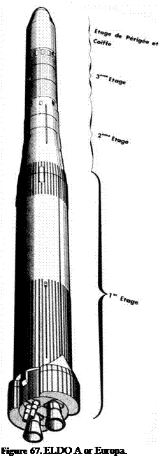
Europa was a three-stage vehicle (the Perigee Apogee System of Europa II was sometimes claimed as a fourth stage), the first stage being a modified Blue Streak, which had an overall length of 60 ft 4 inches (18.4 m) and a diameter of 10 ft (3.05 m). The take-off mass was 197,500 lb (89.4 tonnes), which included
126,0 lb (57 tonnes) of liquid oxygen and 56,300 lb (25.5 tonnes) of kerosene fuel. At the first stage engine cut-off, the mass remaining, including residual propellants and tank pressurisation gas, was 15,200 lb (6.8 tonnes).
The liquid oxygen was held in the upper tank, which was a pressurised shell without stringers or frames, constructed of welded stainless steel sections with a minimum thickness of 0.019 inch (0.48 mm). The kerosene tank was also of stainless steel but strengthened with internal frames and stiffeners and external longitudinal stringers. The two tanks were separated by a deep domed diaphragm built up of welded segments, and similar domes closed off the top and bottom ends of the tank assembly. The liquid oxygen tank was fitted with anti-slosh baffles.
The propulsion bay was attached to the tanks by a short cylindrical skirt structure which was designed to transfer the thrust loads to the tanks above. In the propulsion bay were two thrust beams from which the rocket engines were gimballed, and the ends of these beams, as well as transmitting the thrust loads, acted as support points for the vehicle in the launcher stand. The bay was of light alloy construction, and housed the combustion chambers, the propellant pump assemblies, the engine control systems, as well as the hydraulic pumps and servo – jacks for swivelling the combustion chambers. The bay was closed at the rear end by a heat shield to keep out exhaust gases and radiant heat from the rocket exhausts. Two panniers were placed on either side of the propulsion bay to house more equipment and instrumentation.
There was initially considerable technical discussion – and controversy – as to the best way to design the tanks, which were the major structural element, and the one where most weight could be saved. It was realised that the high internal pressure – about two atmospheres – required to avoid cavitation at the propellant turbopump inlets could be used to stiffen up a very light structure so that it could take heavy longitudinal and bending loads. A pressure of 30 psi over a 10 ft diameter circle represents a total force of 340,000 lb, which was quite adequate to accelerate upper stages of around 35,000 lb to an acceleration of some 7-8 g.
 The liquid oxygen tank was put forward of the kerosene tank in order to bring the centre of gravity as far forward as possible with respect to the centre of pressure, so as to ease the task of the control system. A lighter kerosene tank structure could be obtained if some of the end loading were taken by stringers and frames, since the mass of the liquid oxygen tank under acceleration would need excessively high pressures in the tank.
The choice of tank material, too, was the subject of considerable study, both light alloy and stainless steel being close contenders. It was essential for the tank material to have good strength at liquid oxygen temperature (-183 °C), to be able to withstand kinetic heating, to be readily and efficiently weldable, and be available in uniform sheets of closely controlled thickness. Stainless steel was eventually chosen, made by Firth
Vickers for railway coaches, and with very good physical properties over the range of temperatures required. Individual cylindrical sections were prefabricated from 36 inch wide strips of material.
The two Rolls Royce RZ 2 rocket engines each had a rated thrust at launch of
150,0 lb, giving a take-off acceleration of 1.3 g. The original thrust rating of the RZ 2 engine was 137,000 lb, and this was used for the single stage flights. The higher rating, obtained by an increase in combustion chamber pressure, was used in the later flights.
The turbines were driven by hot gases produced by fuel rich combustion of a small proportion of the main propellants in separate gas generators, and two turbopump units supplied the propellants to the regeneratively cooled thrust chambers. The bright yellow plumes produced from the gas generators can be seen very clearly as the vehicle lifts off. The total propellant flow rate was 1,210 lb/s for the two motors. At high altitudes, the thrust of an engine increases, due both to an improvement in specific impulse brought about by a more efficient expansion of the exhaust gases, and to increases in propellant flow rates as the hydrostatic heads at the propellant pumps rise with vehicle acceleration. Sea level S. I. was around 248, vacuum S. I. was around 285.
The main function of the pressurisation system was to provide pressure in the liquid oxygen tank to preserve its structural integrity, to provide sufficient pressure at the pump inlets to suppress cavitation, and to control boiling of the liquid oxygen. The pressurisation system operated in two principal modes: ‘standby’, with the tanks full of propellants, the pressure in the liquid oxygen tank was maintained at about 9 lb/in2 and about 5 lb/in2 in the kerosene tank; and ‘flight’, when the pressures were raised to 30 and 15 lb/in2 respectively, starting about one minute before lift-off. The ‘standby’ pressures were chosen to provide adequate stability of the vehicle under conditions of ground loading, winds, etc., and the liquid oxygen in its tank would be in a state of equilibrium boiling. For ‘flight’, a low-pressure vent valve on the liquid oxygen tank was closed, and the combined effects of atmospheric heat input and of nitrogen supply from the pneumatic control unit raised the pressure to flight level in about 30 seconds. During the raising of pressure in the liquid oxygen tank, the pressure in the kerosene tank was raised so that the differential pressure across the intertank diaphragm was maintained at a safe value. The engines were then started. During flight, internal supplies of gas were needed so that the pumps did not cavitate or the tanks collapse. This was done with two heat exchangers or evaporators, one of which used the waste heat in the exhaust gases from one turbine to provide gaseous oxygen for pressurising the liquid oxygen tank, using a feed from the liquid oxygen pump discharge. The other, associated with the other engine,
evaporated liquid nitrogen supplied from a storage bottle on the vehicle to pressurise the kerosene tank.
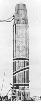
One distinguishing feature of the flight models of Blue Streak (and, later, Black Arrow) was the spiral painted around the vehicle, which can be seen in the photograph on the right. This was for the benefit of the cameras filming the launch, and was the brainchild of an Australian mathematician, Mary Whitehead. In an interview some years later, she had this to say of the pattern:

 The zig-zag pattern on the Blue Streak – that was at my request, because we were required to know whether the missile rolled as it went off [the launcher]. There were, I think, three or four cameras – they were called launcher high speed cameras – around [the launch site], so with that pattern, if the rocket rolled you could measure it really easily, depending on where that diagonal was relevant to the top and bottom stripes.
I had seen the black and white checks that were used on other missiles. I think that might have been in America, and this was the same sort of thing. But making a continuous line like that, you could measure to a degree whether or not it had rolled: as far as I know, I don’t think they did.
The interstage skirt was a stainless steel corrugated truncated cone, 1.23 m high, tapering from 2.8 m to
2.0 m, which weighed 137 kg. A small solid fuel motor was used to separate the two stages: it provided a thrust of 40 kN for 2 seconds.
The design of the second stage, also called Coralie, was constrained by several factors. Its size was set by the weight that Blue Streak could carry, and Blue Streak had been designed as a ballistic missile, not as the first stage of a satellite launcher. The 2 m (approximately 78 inches) diameter was certainly wider than the planned 54-inch Black Knight stage, which had the advantage that the vehicle was less flexible. The original brochure design had only one motor: the four motor design made control easier, particularly in the roll mode, and also meant that the interstage structure could be shorter and thus lighter.
The stage had a mass of 1,850 kg, of which 9,850 kg were fuel (100 kg of this was left at burn out) – 6,440 kg of dinitrogen tetroxide and 3,410 kg of UDMH. The chambers were pressure-fed from a gas generator, which used 41 kg of dinitrogen tetroxide together with 18.5 kg of UDMH and 98 kg of water, the water being used to lower the temperature of the gases to 350 °C. The pressure in the tanks was maintained at 18.6 bar (the combustion chamber pressure was 13.7 bar). Each chamber had a thrust of 68.1 kN (15,300lb) and a burn time of 75 seconds.
 There is no doubt that choice of pressurised tanks did make the stage structurally rather inefficient. The choice was made in part to save time – the French had had little experience with turbopumps. A gas generator was lighter than simply using compressed helium gas, and a similar system had been in use on the Veronique sounding rocket. In addition, the same gases were used to drive the steering mechanism for the chambers and to generate the on-board electrical power supply.
Attempts were made to test the stage separately, with a vehicle called Cora1. The Cora 1 version used only the French Coralie stage, while the Cora 2 version added the German Astris stage. The Italian Europa nose fairing was also tested. For these tests the rocket nozzles were shortened to allow sea-level operation and four fins were added for stability. In the event, only the Cora 1 version was tested, and this failed on two out of three attempts.
The interstage structure was a cylinder 1.23 m long with a mass of 137 kg. Separation of the third stage was by explosive bolts, which caused problems in some of the early flights.
The German third stage, also known as Astris, was powered by dinitrogen tetroxide and Aerozine 50, an equal mixture of hydrazine and UDMH. This was stored in a spherical titanium tank 1.2 mm thick. The helium gas was stored in two bottles made of glass re-inforced plastic pressurised to 300 bar. The main motor had a thrust of 22.5 kN and two small control chambers of 500 N thrust (in vacuum). Since the chambers were to run in vacuum, the pressure in the chambers was a relatively low 11 bar. For a small vacuum stage where a restart capability could be useful, a pressure feed had advantages over turbopumps. The all-up mass was 3,370 kg (7,420 lb) and the empty mass was 610 kg (1,340 lb).
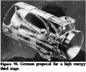
Germany had, of course, been the world leader in rocketry up to 1945, but the diaspora of rocket scientists and technicians, coupled with the perceived militaristic nature of rocketry development, meant that no significant work had been done since. On the other hand, there are advantages in starting again from scratch. Some of the initial German ideas for the third stage were very ambitious, and design studies for a high energy stage were outlined by Dietrich Koelle of Bolkow at a European Spaceflight Symposium in May 1963 . The paper mentioned that ‘Since 1961 intensive studies have been carried out at Bolkow Entwicklungen concerning an optimised high energy stage OPMOS’.
The three designs were ‘based on the propellant combinations H2/O2 and H2/F2 pressure-fed, and H2/O2 pump-fed. The results of the studies indicate that the payload capacity of the ELDO launch vehicle can be increased by the
 introduction of a high energy upper stage from the present 220 lb to some 1,550 lb for escape missions.’ The studies were not merely theoretical: ‘Small hydrogen cooled engines have been on test for some time at the firm of Bolkow’.
The motor chamber was also distinctly unusual. It would provide 8,650 lb thrust, and used an Expansion – Deflection nozzle, where the flow is expanded radially and then turned axially. It has the advantages that it is a good deal shorter than the conventional rocket chamber, as seen in the artist’s representation above, and also allows for a greater expansion of the exhaust gases.
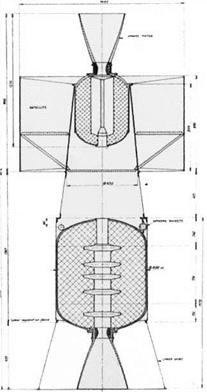
Calling the PAS a fourth stage was perhaps overdoing things slightly, but it was designed to enable Europa to put a satellite into geostationary orbit. It was described thus by J. Nouaille, who was the Project Management Director, in 1968:
… A lower metallic skirt attaches the stage to the top of the Europa I third stage. At the upper part of this skirt a separation mechanism releases the PAS system from the third stage when appropriate.
Four small rockets fixed on top of the perigee motor, approximately in the plane of the centre of gravity of the PAS system, spin up the vehicle, as soon as separated from the third stage, to a velocity of 120 rpm.
The perigee motor is then ignited, giving the vehicle an increment in velocity of approximately 2,450 m/s.
The main characteristics of this motor are:
empty mass 70 kg mass of propellant 685 kg
specific impulse 278 s maximum pressure 61 bar
maximum acceleration 10.3g
After burnout of the motor, a second separation occurs between the empty spinning perigee stage and the spinning satellite.
During the whole of its operation, the perigee stage is controlled and monitored by electronic equipments attached inside the upper skirt of the stage (equipment bay).
Apogee Motor.
The apogee motor is part of the satellite. It is ignited by a telecommand order at the most appropriate moment, taking into account the actual orbit and attitude data of the satellite.
Its main characteristics are:
empty mass 36 kg propellant mass 156 kg
specific impulse 270 s maximum pressure 42 bars
velocity increment 1470 m/s approximately.
The launching procedure of the ELDO-PAS satellite… includes
(a) an injection from Guiana into a parking orbit by the three lower stages of the launcher: after burn-out of the third stage, the attitude of the vehicle remains controlled by a cold gas jet system installed on the third stage. The platform of the Inertial Guidance system is used as a reference during this phase. Ground stations in Kourou (Guiana), Fortalezza (Brazil) and Brazzaville (Congo) are used to monitor the vehicle.
(b) When crossing the Equator, approximately at the longitude of Brazzaville, an accurate orientation of the PAS system is achieved, the PAS assembly is separated from the third stage, and then, immediately, the perigee motor is ignited, burnt out and separated.
(c)  The satellite is spinning on a transfer orbit about 300 km perigee and 35,000 km apogee. An accurate tracking is obtained from the Gove station (Australia) and the main data on this orbit and on the attitude of the satellite are collected.
These data are transmitted to the main Control Centre in Darmstadt. The optimum time of ignition of the apogee motor is then calculated. Ignition will take place somewhere over the Atlantic, either at the second apogee of the transfer orbit or more probably at the fourth apogee.


