Category NASA’S CONTRIBUTIONS TO AERONAUTICS

The Future of Dynamic Model Testing

Efforts by the NACA and NASA over the last 80 years with applications of free-flying dynamic model test techniques have resulted in signifi­cant contributions to the civil and military aerospace communities. The results of the investigations have documented the testing techniques and lessons learned, and they have been especially valuable in defining critical characteristics of radical new configurations. With the passing of each decade, the free-flight techniques have become more sophis­ticated, and the accumulation of correlation between model and full – scale results has rapidly increased. In view of this technical progress, it

The Future of Dynamic Model Testing

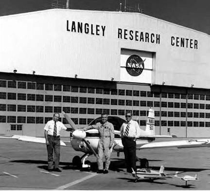
Langley researchers Long Yip, left, and David Robelen with a radio-controlled model used in a program on spin resistance with the DeVore Aviation Corporation. The model was equipped with NASA-developed discontinuous outboard droops and was extremely spin resistant. NASA.

is appropriate to reflect on the state of the art in free-flight technology and the challenges and opportunities of the future.

Bringing the Tunnel to Industry and Academia

NASA has always justified its existence by making itself available for outside research. In an effort to advertise the services and capabilities of Langley’s wind tunnels, NASA published the technical memorandum, "Characteristics of Major Active Wind Tunnels at the Langley Research Center,” by William T. Shaefer, Jr., in July 1965. Unlike the NACA’s goal of assisting industry through the use of its pioneering wind tunnels at a time when there were few facilities to rely upon, NASA’s wind tunnels first and foremost met the needs of the Agency’s fundamental research and development. Secondary to that priority were projects that were important to other Government agencies. Two specific committees han­dled U. S. Army, Navy, and Air Force requests concerning aircraft and missiles and propulsion projects. Finally, the aerospace industry had access to NASA facilities, primarily the Unitary Plan Wind Tunnels, on a fee basis for the evaluation of proprietary designs. No NASA wind tun­nel was to be used for testing that could be done at a commercial facil­ity, and all projects had to be "clearly in the national interest.”[625]

NASA continued to "sell” its tunnels on through the following decades. In 1992, the Agency confidently announced:

NASA’s wind tunnels are a national technological resource. They have provided vast knowledge that has contributed to the development and advancement of the nation’s aviation industry, space program, economy and the national security. Amid today’s increasingly fierce international, commercial and technological competi­tion, NASA’s wind tunnels are crucial tools for helping the United States retain its global leadership in aviation and space flight.[626]

According to this rhetoric, NASA’s wind tunnels were central to the continued leadership of the United States in aerospace.

As part of the selling of the tunnels, NASA initiated the Technology Opportunities Showcase (TOPS) in the early 1990s. The program distrib­uted to the aerospace industry a catalog of available facilities similar to a real estate sampler. A prospective user could check a box marked "Please Send More Information” or "Would Like To Discuss Facility Usage” as part of the process. NASA wind tunnels were used on a space-available basis. If the research was of interest to NASA, there would be no facility charge, and the Agency would publish the results. If a manufacturing concern had a proprietary interest and the client did not want the test results to be public, then it had to bear all costs, primarily the use of the facility.[627]

The TOPS evolved into the NASA Aeronautics Test Program (ATP) in the early 21st century to include all four Research Centers at Langley, Ames, Glenn, and Dryden.[628] The ATP offered Government, corpora­tions, and institutions the opportunity to contract 14 facilities, which included a "nationwide team of highly trained and certified staff, whose backgrounds and education encompass every aspect of aerospace test­ing and engineering,” for a "wide range” of experimental test services that reflected "sixty years of unmatched aerospace test history.” The ATP

and, by extension, NASA maintained that they could provide clients test results of "unparalleled superiority.”[629]

THE NASA AERONAUTICS TEST PROGRAM WIND TUNNELS, 2009

WIND TUNNEL

SPEED

LOCATION

9- by 15-Foot Low-Speed Wind Tunnel

Mach 0 to 0.2

Glenn

14- by 22-Foot Subsonic Tunnel

Mach 0 to 0.3

Langley

20-Foot Vertical Spin Tunnel

Mach 0 to 0.08

Langley

Icing Research Tunnel

Mach 0.06 to 0.56

Glenn

1 1-Foot Transonic Unitary Plan Facility

Mach 0.2 to 1.45

Ames

National Transonic Facility

Mach 0.1 to 1.2

Langley

Transonic Dynamics Tunnel

Mach 0.1 to 1.2

Langley

10- by 10-Foot Supersonic Wind Tunnel

Mach 0 to 0.4/2.0 to 3.5

Glenn

8- by 6-Foot Supersonic Wind Tunnel

Mach 0.25 to 2.0/0.0 to 0.1

Glenn

4-Foot Supersonic Unitary Plan Wind Tunnel

Mach 1.5 to 2.9/2.3 to 4.6

Langley

9- by 7-Foot Supersonic Wind Tunnel

Mach 1.55 to 2.55

Ames

Propulsion Systems Laboratory

Mach 4

Glenn

8-Foot High-Temperature Tunnel

Mach 3, 4, 5, 7

Langley

Aerothermodynamics Laboratory

Mach 6, 10

Langley

Crash Impact Research

In support of the Apollo lunar landing program, engineers at the Langley Research Center had constructed a huge steel A-frame gantry structure, the Lunar Landing Research Facility (LLRF). Longer than a football field and nearly half as high as the Washington Monument, this facility proved less useful for its intended purposes than free-flight jet-and-rocket powered training vehicles tested and flown at Edwards and Houston. In serendipitous fashion, however, it proved of tremendous value for aviation safety after having been resurrected as a crash-impact test facility, the Impact Dynamics Research Facility (IDRF) in 1974, coincident with the conclusion of the Apollo program.[851]

Подпись: Test Director Victor Vaughan studies the results of one 1 974 crash impact test at the Langley Impact Dynamics Research Facility. NASA. Подпись: 8

Over its first three decades, the IDRF was used to conduct 41 full – scale crash tests of GA aircraft and approximately 125 other impact tests of helicopters and aircraft components. The IDRF could pendulum-sling aircraft and components into the ground at precise impact angles and velocities, simulating the dynamic conditions of a full-scale accident

or impact.[852] In the first 10 years of its existence, the IDRF served as the focal point for a joint NASA-FAA-GA industry study to improve the crashworthiness of light aircraft. It was a case of making the best of a bad situation: a flood had rendered a sizeable portion of Piper’s single – and-twin-engine GA production at its Lock Haven, PA, plant unfit for sale and service.[853] Rather than simply scrap the aircraft, NASA and Piper worked together to turn them to the benefit of the GA industry and user communities. A variety of Piper Aztecs, Cherokees, and Navajos, and later some Cessna 172s, some adorned with colorful names like "Born to Lose,” were instrumented, suspended from cable harnesses, and then "crashed” at various impact angles, attitudes, velocities, and sink-rates, and against hard and soft surfaces. To gain greater fidelity, some were accelerated during their drop by small solid-fuel rockets installed in their engine nacelles.[854]

Later tests, undertaken in 1995 as part of the Advanced General Aviation Transport Experiment (AGATE) study effort (discussed subse­quently), tested Beech Starship, Cirrus SR-20, Lear Fan 2100, and Lancair aircraft.[855] The rapid maturation of computerized analysis programs led to its swift adoption for crash impact research. In partnership with NASA, researchers at the Grumman Corporation Research Center developed DYCAST (DYnamic Crash Analysis of STructures) to analyze structural response during crashes. DYCAST, a finite element program, was quali­fied during extensive NASA testing for light aircraft component testing, including seat and fuselage section analysis, and then made available for broader aviation community use in 1987.[856] Application of computa­
tional methodologies to crash impact research expanded so greatly that by the early 1990s, NASA, in partnership with the University of Virginia Center for Computational Structures Technology, held a seminal work­shop on advances in the field.[857] Out of all of this testing came better understanding of the dynamics of an accident and the behavior of air­craft at and after impact, quantitative data applicable to the design of new and more survivable aircraft structures, better seats and restraint systems, comparative data on the relative merits of conventional ver­sus composite construction, and computational methodologies for ever­more precise and informed analysis of crashworthiness.

Toward Precision Autonomous Spacecraft Recovery

From October 1991 to December 1996, a research program known as the Spacecraft Autoland Project was conducted at Dryden to determine the feasibility of autonomous spacecraft recovery using a ram-air parafoil system for the final stages of flight, including a precision landing. The latter characteristic was the focus of a portion of the project that called for development of a system for precision cargo delivery. NASA Johnson Space Center and the U. S. Army also participated in various phases of the program, with the Charles Stark Draper Laboratory of Cambridge, MA, developing Precision Guided Airdrop Software (PGAS) under contract to the Army.[989] Four generic spacecraft models (each called a Spacewedge, or simply Wedge) were built to test the concept’s feasibility. The proj­ect demonstrated precision flare and landing into the wind at a pre­determined location, proving that a flexible, deployable system that entailed autonomous navigation and landing was a viable and practical way to recover spacecraft.

Key personnel included R. Dale Reed, who participated in flight-test operations. Alexander Sim managed the project and documented the results. James Murray served as the principal Dryden investigator and as lead for all systems integration for Phases I and II. He designed and fabricated much of the instrumentation for Phase II and was the lead for flight data retrieval and analysis in Phases II and III. David Neufeld performed mechanical integration for the Wedge vehicles’ systems dur­ing all three phases and served as parachute rigger, among other duties. Philip Hattis of the Charles Stark Draper Laboratory served as the proj­ect technical director for Phase III. For the Army, Richard Benney was the technical point of contact, while Rob Meyerson served as the tech­nical point of contact for NASA Johnson and provided the specifica­tions for the Spacewedges.[990] The Spacewedge configuration consisted of a flattened biconic airframe joined to a ram-air parafoil with a cus­tom harness. In the manual control mode, the vehicle was flown using radio uplink. In the autonomous mode, it was controlled using a small computer that received inputs from onboard sensors. Selected sensor data were recorded onto several onboard data loggers.

Two Spacewedge shapes, resembling half cones with a flattened bot­tom, were used for four airframes that represented generic hypersonic vehicle configurations. Wedge 1 and Wedge 2 had sloping sides, and the underside of the nose sloped up slightly. Wedge 3 had flattened sides, to create a larger internal volume for instrumentation. The Spacewedge vehi­cles were 48 inches long, 30 inches wide, and 21 inches in height. The basic weight was 120 pounds, although various configurations ranged from 127 to 184 pounds during the course of the test program. Wedge 1 had a tubular steel structure, covered with plywood on the rear and underside that could withstand hard landings. It had a fiberglass-covered wooden nose and removable aluminum upper and side skins. Wedge 2, originally uninstrumented, was later configured with instrumentation. It had a fiberglass outer shell, with plywood internal bulkheads and bottom structure. Wedge 3 was constructed as a two-piece fiberglass shell, with a plywood and aluminum shelf for instrumentation.[991] A commercially available 288-square-foot ram-air parafoil of a type commonly used by sport parachutists was selected for Phase I tests. The docile flight charac­teristics, low wing loading, and proven design allowed the project team to concentrate on developing the vehicle rather than the parachute. With the exception of lengthened control lines, the parachute was not modi­fied. Its large size allowed the vehicle to land without flaring and without sustaining damage. For Phase II and III, a smaller (88 square feet) para­foil was used to allow for a wing loading more representative of space vehicle or cargo applications.

Spacewedge Phase I and II instrumentation system architecture was driven by cost, hardware availability, and program evolution. Essential items consisted of the uplink receiver, Global Positioning System (GPS) receiver and antenna, barometric altimeter, flight control computer, servo – actuators, electronic compass, and ultrasonic altimeter. NASA techni­cians integrated additional such off-the-shelf components as a camcorder, control position transducers, a data logger, and a pocket personal com­puter. Wedge 3 instrumentation was considerably more complex in order to accommodate the PGAS system.[992] Spacewedge control systems had programming, manual, and autonomous flight modes. The programming mode was used to initialize and configure the flight control computer. The manual mode incorporated a radio-control model receiver and uplink transmitter, configured to allow the ground pilot to enter either brake (pitch) or turn (yaw) commands. The vehicle reverted to manual mode whenever the transmitter controls were moved, even when the autono­mous mode was selected. Flight in the autonomous mode included four primary elements and three decision altitudes. This mode allowed the vehicle to navigate to the landing point, maintain the holding pattern while descending, enter the landing pattern, and initiate the flare maneu­ver. The three decision altitudes were at the start of the landing pattern, the turn to final approach, and the flare initiation.

NASA researchers initially launched Wedge 1 from a hillside near the town of Tehachapi, in the mountains northwest of Edwards, to evaluate general flying qualities, including gentle turns and landing flare. Two of these slope soar flights were made April 23, 1992, with approximately 15-knot winds, achieving altitudes of 10 to 50 feet. The test program was then moved to Rogers Dry Lake at Edwards and to a sport parachute drop zone at California City.115 A second vehicle (known as Inert Spacewedge, or Wedge 2) was fabricated with the same external geometry and weight as Wedge 1. It was initially used to validate parachute deployment, har­ness design, and drop separation characteristics. Wedge 2 was inexpen­sive, lacked internal components, and was considered expendable. It was first dropped from a Cessna U-206 Stationair on June 10, 1992. A sec­ond drop of Wedge 2 verified repeatability of the parachute deployment system. The Wedge 2 vehicle was also used for the first drop from a Rans S-12 ultralight modified as a RPV on August 14, 1992. Wedge 2 was later instrumented and used for ground tests while mounted on top of a van, becoming the primary Phase I test vehicle.116 Thirty-six flight tests were conducted during Phase I, the last taking place February 12, 1993. These flights, 11 of which were remotely controlled, verified the vehicle’s manual and autonomous landing systems. Most were launched from the Cessna U-206 Stationair. Only two flights were launched from the Rans S-12 RPV.

Phase II of the program, from March 1993 to March 1995, encom­passed 45 flights using a smaller parafoil for higher wing loading [993] [994] (2 lb/ft2) and incorporating a new guidance, control, and instrumentation system developed at Dryden. The remaining 34 Phase III flights evaluated the PGAS system using Wedge 3 from June 1995 to December 1996. The software was developed by the Charles Stark Draper Laboratory under contract to the U. S. Army to develop a guidance system to be used for precision offset cargo delivery. The Wedge 3 vehicle was 4 feet long and was dropped at weights varying from 127 to 184 pounds.[995] Technology developed in the Spacewedge program has numerous civil and military applications. Potential NASA users for a deployable, precision, autono­mous landing system include proposed piloted vehicles as well as plan­etary probes and booster-recovery systems. Military applications of autonomous gliding-parachute systems include recovery of aircraft ejec­tion seats and high-altitude, offset delivery of cargo to minimize danger to aircraft and crews. Such a cargo delivery system could also be used for providing humanitarian aid.[996] In August 1995, R. Dale Reed incor­porated a 75-square-foot Spacewedge-type parafoil on a 48-inch-long, 150-pound lifting body model called ACRV-X. During a series of 13 flights at the California City drop zone, he assessed the landing characteris­tics of Johnson Space Center’s proposed Assured Crew Return Vehicle design (essentially a lifeboat for the International Space Station). The instrumented R/C model exhibited good flight control and stable ground slide-out characteristics, paving the way for a larger, heavyweight test vehicle known as the X-38.[997]

XB-70 Supersonic Cruise Program Takes to the Air

Despite the AV-1 aircraft limitations, the XB-70 test program proceeded, now with NASA directing the effort with USAF support. Eleven flights were flown under NASA direction as Phase II of the original XB-70 planned flight-test program, ending January 31, 1967. Nine of the
flights were primarily dedicated to the NSBP. As the XB-70 was the only aircraft in the world with the speed, altitude capability, and weight of the U. S. SST, priority was given to aspects that supported that program. The sonic boom promised to be a factor that was drastically different from current jet airliner operations and one whose initial impact was underrated. It was thought that a rapid climb to high altitude before going supersonic would muffle the initial strong normal shock; once at high altitude, even at higher Mach numbers, the boom would be sufficiently attenuated by distance from the ground and the shock wave inclination "lay back” as Mach number increased, to not be a disturbance to ground observers. This proved not to be the case, as over­flights by B-58s and the XB-70 proved. Another case study in this vol­ume provides details on sonic boom research by NASA. Overpressure measurements on the ground during XB-70 overflights as well as the observer questionnaires and measurements in instrumented homes constructed at Edwards AFB indicated that overland supersonic cruise would produce unacceptable annoyance to the public on the ground. Overpressure beneath the flight path reached values of 1.5 to 2 pounds per square foot. A lower limit goal of not more than 0.5 pounds per foot to preclude ground disturbance seemed unachievable with current designs and technology.[1084]

Подпись: 10Supersonic cruise test missions proved challenging for pilots and flight-test engineers alike. Ideally, the test conductor on the ground would be in constant contact with the test pilots to assist in most efficient use of test time. But with an aircraft traveling 25-30 miles per minute, the aircraft rapidly disappeared over the horizon from test mission control. Fortunately, NASA had installed a 450-mile "high range” extending to Utah, with additional tracking radars, telemetry receivers, and radio relays for the hypersonic X-15 research rocket plane. The X-15 was typically released from the B-52 at the north end of the range and was back on the ground within 15 minutes. The high range provided extended mission command and control and data collection but was not optimized for the missions flown by the XB-70 and YF-12.

The XB-70 ground track presented a different problem for mission planners. The author flew the SR-71 Blackbird from Southern California for 5 years and faced the same problems in establishing a test ground track. The test aircraft would take over 200 miles to get to the test cruise speed and altitude. Then it would remain at test conditions, collecting data for 30-40 minutes. It then required an additional 200-250 miles to slow to "normal” subsonic flight. Ground tracks had to be estab­lished that would provide data collection legs while flying straight or performing planned turning maneuvers, and avoiding areas that would be sensitive to the increasingly contentious sonic booms. Examples of the areas included built-up cities and towns; the "avoidance radius” was generally 30 nautical miles. Less obvious areas included mink farms and large poultry ranches, as unexplained sudden loud noises could apparently interfere with breeding habits and egg-laying practices. The Western United States fortunately had a considerably lower population density than the area east of the Mississippi River, and test tracks could be established on a generally north-south orientation.

Подпись: 10The presence of Canada to the north and Mexico to the south, not to mention the densely populated Los Angeles/San Diego corridor and the "island” of Las Vegas, set further bounding limits. Planning a test profile that accounted for the limits/avoidance areas could be a challenge, as the turn radius of a Mach 3 aircraft at 30 degrees of bank was over 65 nautical miles. Experience and the sonic boom research showed that a sonic boom laid down by a turning or descending super­sonic aircraft would "focus” the boom on the ground, decreasing the area affected but increasing the overpressure on the ground within a smaller region. Because planning ground tracks was so complicated and arduous, once a track was established, it tended to be used numerous times. This in turn increased the frequency of residents being subjected to sudden loud noises, and complaints often appeared only after a track had been used several times. The USAF 9th Reconnaissance Wing operating the Mach 3+ SR-71 at Beale Air Force Base near Sacramento, CA, had the same problem as NASA flight-testing for developing training routes (but without the constraints of maintaining telemetry contact with a test control), and it soon discovered another category for avoidance areas: congressional complaints relayed from the Office of the Secretary of the Air Force.

For the limited XB-70 test program, a ground track was established that remained within radio and telemetry range of Edwards. As a result,
the aircraft at high Mach would only fly straight and level for 20 min­utes at best, requiring careful sequencing of the test points. The profile included California, Nevada, and Utah.[1085]

Подпись: 10This planning experience was a forerunner of what problems a fleet of Supersonic Transports would face on overland long-distance flights if they used their design speed. A factor to be overcome in supersonic cruise flight test, it would be critical to a supersonic airliner. Pending development of sonic boom reduction for an aircraft, the impact of off – design-speed operation over land would have to be factored into SST designs. This would affect both range performance and economics.

The flight tests conducted on the XB-70 missions collected data on many areas besides sonic boom impact. The research data were gen­erally focused on areas that were a byproduct of the aeronautical tech­nology inherent in a large airplane designed to go very fast for a long distance with a large payload. An instrumentation package was devel­oped to record research data.[1086] Later, boundary layer rakes were installed to measure boundary layer growth on the long fuselage at high Mach at

70,0 feet altitude; this would influence the drag and hence the range performance of a design. The long flexible fuselage of the XB-70 pro­duced some interesting aeroelastic effects when in turbulence, not to mention taxing over a rough taxiway, similar to the pilot being on a div­ing board. Two 8-inch exciter vane "miniature canards” were mounted near the cockpit as part of the Identically Located Acceleration and Force (ILAF) experiment for the final XB-70 flight-test sorties. These vanes could be programmed to oscillate to induce frequencies in the fuselage to explore its response. Additionally, frequencies could be pro­duced to cancel accelerations induced by turbulence or gusts, leading to a smoother ride for pilots and ultimately SST passengers. This sys­tem was demonstrated to be effective.[1087] A similar system was employed in the Rockwell B-1 Lancer bomber, the Air Force bomber eventually built instead of the B-70.

Inlet performance would have a critical effect on the specific fuel consumption performance, which had a direct effect on range achieved. In addition to collecting inlet data on all supersonic cruise sorties,
numerous test sorties involved investigating inlet unstarts deliberately induced by pilot action, as well as the "unplanned” events. This was important for future aircraft, as the Valkyrie used a two-dimensional (rectangular) inlet with mixed external (to the inlet)/internal compres­sion, with one inlet feeding multiple engines. As a comparison, the A-12/ SR-71 used an axisymmetric (round) inlet, also with external/internal compression feeding a single engine. There was a considerable debate in the propulsion community in general and the Boeing and Lockheed competitive SST designers in particular as to which configuration was better. Theoretical values of pressure recovery had been tested in propul­sion installations in wind tunnels, but the XB-70 presented an opportu­nity to collect data and verify wind tunnel results in extended supersonic free-flight operations, including "off-design” conditions during unstart operations. These data were also important as an operational SST fac­tor, as inlet unstarts were disconcerting to pilots, not to mention pro­spective passengers.

Подпись: 10Traditional aircraft flight-test data on performance, stability, con­trol, and handling qualities were collected, although AV-1 was limited to Mach 2.5 and eventually Mach 2.6. Data to Mach 3 were sometimes also available from AV-2 flights. As USAF-NASA test pilot Fitzhugh Fulton reported in a paper presented to the Society of Automotive Engineers (SAE) in 1968 in Anaheim, CA, on test results as applied to SST opera­tions, the XB-70 flew well, although there were numerous deficiencies that would have to be corrected.[1088] The airplane’s large size and delta wing high-incidence landing attitude required pilot adjustments in take­off, approach, and landing techniques but nothing extraordinary. High Mach cruise was controllable, but the lack of an autopilot in the XB-70 and the need of the pilot to "hand-fly” the airplane brought out another pilot interface problem; at a speed of nearly 3,000 feet per second, a change in pitch attitude of only 1 degree would produce a healthy climb or descent rate of 3,000 feet per minute (50 feet per second). Maintaining a precise altitude was difficult. Various expanded instrument displays were used to assist the task, but the inherent lag in Pitot-static instru­ments relying on measuring tiny pressure differentials (outside static pressure approximately 0.5 pounds per square inch [psi]) to indicate altitude change meant the pilot was often playing catchup.

High Mach cruise at 70,000 feet may have become routine, but it required much more careful flight planning than do contemporary sub­sonic jet operations. The high fuel flows at high Mach numbers meant that fuel reserves were critical in the event of unplanned excursions in flight. Weather forecasts at the extreme altitudes were important, as temperature differences at cruise had a disproportionate influence on fuel flows at a given Mach and altitude; 10 °F hotter than a standard day at altitude could reduce range, requiring an additional fuel stop, unless it was factored into the flight plan. (Early jet operations over the North Atlantic had similar problems; better weather forecasts and larger aircraft with larger fuel reserves rectified this within several years.) Supersonic cruise platforms traveling at 25-30 miles per minute had an additional problem. Although the atmosphere is generally portrayed as a "layer cake,” pilots in the XB-70 and Mach 3 Blackbird discovered it was more like a "carrot cake,” as there were localized regions of hot and cold air that were quickly traversed by high Mach aircraft This could lead to range performance concerns and autopilot instabilities in Mach hold because of the temperature changes encountered. The increase in stagnation temperatures on a hot day could require the aircraft to slow because of engine compressor inlet temperature (CIT) limitations, fur­ther degrading range performance.

Подпись: 10Fuel criticality and the over 200 miles required to achieve and descend from the optimum cruise conditions meant that the SST could brook no air traffic control delays, so merging SST operations with sub­sonic traffic would stress traffic flow into SST airports. Similar concerns about subsonic jet airliner traffic in the mid-1950s resulted in revamp­ing the ATC system to provide nationwide radar coverage and better automate traffic handoffs. To gather contemporary data on this problem for SST concerns, NASA test pilots flew a Mach 2 North American A-5A (former A3J-1) Vigilante on supersonic entry profiles into Los Angeles International Airport. The limited test program flying into Los Angeles showed that the piloting task was easy and that the ATC system was capable of integrating the supersonic aircraft into the subsonic flow.[1089]

One result mentioned in test pilot Fulton’s paper had serious impli­cations not only for the SST but also supersonic research. The XB-70
had been designed using the latest NASA theories (compression lift) and NASA wind tunnels. Nevertheless, the XB-70 as flown was deficient in achieving its design range by approximately 25 percent. What was the cause of the deficiency? Some theorized the thermal expansion in such a large aircraft at cruise Mach, unaccounted for in the wind tun­nels, increased the size of the aircraft to the point where the reference areas for the theoretical calculations were incorrect. Others thought the flexibility of the large aircraft was unaccounted for in the wind tunnel model configuration. Another possibility was that the skin friction drag on the large surface area at high Mach was higher than estimated. Yet another was that the compression lift assumption of up to 30-percent enhancement of lift at cruise speed was incorrect.

Подпись: 10The limited duration of the XB-70 test program meant that further flight tests could not be flown to investigate the discrepancy. Flight – test engineer William Schweikhard proposed a reverse investigation. He structured a program that would use specific flight-test conditions from the program and duplicate them in wind tunnels using high- fidelity models of the XB-70 built to represent the configuration of the aircraft as it was estimated to exist at Mach 2.5. The flight-test data would thus serve as a truth source for the tunnel results.[1090] This comparison showed good correlation between the flight-test data and the wind tun­nel, with the exception of a 20-percent-too-low transonic drag estimate, mainly caused by an incorrect estimate of the control surface deflec­tion necessary to trim the aircraft at transonic speeds. It was doubtful that that would account for the range discrepancy, because the aircraft spent little time at that speed.

The NASA test program with the XB-70 extended from June 16, 1966, to January 22, 1969, with the final flight being a subsonic flight to the Air Force Museum at Wright-Patterson Air Force Base in Dayton, OH. Thirty-four sorties were flown during the program. The original funding agreement with the USAF to provide B-58 chase support and mainte­nance was due to expire at the end of 1968, and the XB-70 would require extensive depot level maintenance as envisioned at the end of the 180- hour test program. NASA research program goals had essentially been
reached, and because of the high costs of operating a one-aircraft fleet, the program was not extended. The X-15 program was also terminated at this time.

Подпись: 10The legacy of the XB-70 program was in the archived mountains of data and the almost 100 technical reports written using that data. As late as 1992, the sonic boom test data generated in the NSBP flights were transferred to modern digital data files for use by researchers of high-speed transports.[1091] But it was fitting that the XB-70’s final super­sonic test sortie included collecting ozone data at high altitudes. The United States SST program that would use supersonic cruise research data was about to encounter something that the engineers had not con­sidered: the increasing interest of both decision makers and the public in the social consequences of high technology, exemplified by the rise of the modern environmental movement. This would have an impact on the direction of NASA supersonic cruise research. Never again in the 20th century would such a large aircraft fly as fast as the Valkyrie.

NASA and the Aircraft Icing Gap

At a conference in June 1955, Uwe H. von Glahn, the NASA branch chief in charge of icing research at the then-Lewis Research Center (now Glenn Research Center) in Cleveland boldly told fellow scientific investigators: "Aircraft are now capable of flying in icing clouds without difficulty. . . because research by the NACA and others has provided the engineering basis for ice-protection systems.”[1214]

That sentiment, in combination with the growing interest and need to support a race to the Moon, effectively shut down icing research by

the NACA, although private industry continued to use Government facilities for their own cold-weather research and certification activi­ties, most notably the historic Icing Research Tunnel (IRT) that still is in use today at the Glenn Research Center (GRC). The Government’s return to icing research began in 1972 at a meeting of the Society of Automotive Engineers in Dallas, during which an aeronautics-related panel was set up to investigate ice accretion prediction methods and define where improvements in related technologies could be made. Six years later the panel concluded that little progress in understanding icing had been accomplished since the NACA days. Yet since the for­mation of NASA in 1958, 20 years earlier, aircraft technology had fun­damentally changed. Commercial aviation was flying larger jet airliners and being asked to develop more fuel-efficient engines, and at the same time the U. S. Army was having icing issues operating helicopters in icy conditions in Europe. The Army’s needs led to a meeting with NASA and the FAA, followed by a July 1978 conference with 113 represen­tatives from industry, the military, the U. S. Government, and several nations. From that conference sparked the impetus for NASA restart­ing its icing research to "update the applied technology to the current state of the art; develop and validate advanced analysis methods, test facilities, and icing protection concepts; develop improved and larger testing facilities; assist in the difficult process of standardization and regulatory functions; provide a focus to the presently disjointed efforts within U. S. organizations and foreign countries; and assist in dissem­inating the research results through normal NASA distribution chan­nels and conferences.”[1215]

Подпись: 12While icing research programs were considered, proposed, planned, and in some cases started, full support from Congress and other stake­holders for the return of a major, sustained icing research effort by NASA did not come until after an Air Florida Boeing 737 took off from National Airport in Washington, DC, in a snowstorm and within seconds crashed on the 14th Street Bridge. The 1982 incident killed 5 people on the bridge, as well as 70 passengers and 4 crewmembers. Only five peo­ple survived the crash, which the National Transportation Safety Board blamed on a number of factors, assigning issues related to icing as a major cause of the preventable accident. Those issues included faulting

the flight crew for not activating the twin engine’s anti-ice system while the aircraft was on the ground and during takeoff, for taking off with snow and ice still on the airfoil surfaces of the Boeing aircraft, and for the lengthy delay between the final time the aircraft was de-iced on the tarmac and the time it took the crew to be in position to receive takeoff clearance from the control tower and get airborne. While all this was happening the aircraft was exposed to constant precipitation that at var­ious times could be described as rain or sleet or snow.[1216]

Подпись: 12The immediate aftermath of the accident—including the dramatic rescue of the five survivors who had to be fished out of the Potomac River—was all played out on live television, freezing the issue of air­craft icing into the national consciousness. Proponents of NASA renew­ing its icing research efforts suddenly had shocking and vivid proof that additional research for safety purposes was necessary in order to deal with icing issues in the future. Approval for a badly needed major ren­ovation of the IRT at GRC was quickly given, and a new, modern era of NASA aircraft icing investigations began.[1217]

New Challenges

Arguably, no other technical discipline is as sensitive to configuration features as high-angle-of-attack technology. Throughout World War II, the effects of configuration details such as wing airfoil, wing twist,
engine torque, propeller slipstream, and wing placement were critical and, if not properly designed, often resulted in deficient handing qual­ities accentuated by poor or even vicious stalling behavior. The NACA research staffs at Langley and Ames played key roles in advancing design methodology based on years of accumulated knowledge and lessons learned for straight winged, propeller-driven aircraft. Aberrations of design practice, such as flying wings, had posed new problems such as tumbling, which had also been addressed.[1280] However, just as it appeared that the art and science of designing for high-alpha condi­tions was under control, a wave of unconventional configuration fea­tures emerged in the jet aircraft of the 1950s to challenge designers with new problems. Foremost among these radical features was the use of swept-back and delta wings, long pointed fuselages, and the distribu­tion of mass primarily along the fuselage.

Подпись: 13Suddenly, topics such as pitch-up, inertial coupling, and direc­tional divergence became the focus of high-angle-of-attack technology. Responding to an almost complete lack of design experience in these areas, the NACA initiated numerous experimental and theoretical stud­ies. One of the more significant contributions to design methods was the development of a predictive criterion that used readily obtained aerodynamic wind tunnel parameters to predict whether a configura­tion would exhibit a directional divergence (departure) at high angles of attack.[1281] Typical of many NACA and NASA contributions, the criterion is still used today by designers of high-performance military aircraft.

As the 1950s progressed, it was becoming obvious that high-alpha maneuverability was becoming a serious challenge. Lateral-directional stability and control were difficult to achieve, and the spin and recovery characteristics of the new breed of fighter aircraft were proving to be extremely marginal. In addition to frequent encoun­ters with unsatisfactory spin recovery, dangerous new posstall motions such as disorienting oscillatory spins and fast flat spins were encountered, which challenged the ability of human pilots to effect recovery.[1282]

Подпись: Group photo of X-planes at Dryden in 1 953 exhibit configuration features that had changed dramatically from the straight winged X-1A and D-558-1, at left, to the delta wing XF-92A, top left, the variable-sweep X-5, the swept wing D-558-2, the tailless X-4, and the slender X-3. The changes had significant effects on high-alpha and spin characteristics. NASA. Подпись: 13

Automatic flight control systems were designed to limit the max­imum obtainable angle of attack to avoid these high-angle-of-attack deficiencies, but severe degradations in maneuver capability were imposed by this approach for some designs. Researchers considered automatic spin recovery concepts, but such systems required special sensors and control components not used in day-to-day operations at that time. Concerns over the cost, maintenance, and the impact of inad­vertent actuation of such systems on safety discouraged interest in the development of automatic spin prevention systems.

As the 1950s came to a close, the difficulty of designing for high- angle-of-attack conditions, coupled with the anticipated dominance of emerging air-to-air missile concepts, resulted in a new military perspec­tive on the need for maneuverability. Under this doctrine, maneuverabil­ity required for air-to-air engagements would be built into the missile system, and fighter or interceptor aircraft would be designed as stand­off missile launchers with no need for maneuverability or high-alpha
capability. Not only did this scenario result in a minimal analysis of high-angle-of-attack behavior for emerging designs, it resulted in a significant decrease in the advocacy and support for NASA research on stall/spin problems. In the late 1950s, Langley was even threatened with a closure of its spin tunnel.[1283]

NACA-NASA and Boundary Layer Control, Externally Blown Flap, and Upper Surface Blowing STOL Research

Short Take-Off and Landing flight research was primarily motivated by the desire of military and civil operators to develop transport air­craft with short-field operational capability typical of low-speed air­planes yet the high cruising speed of jets. For Langley and Ames, it was a natural extension of their earlier boundary layer control (BLC) activ­ity undertaken in the 1950s to improve the safety and operational effi­ciency of military aircraft, such as naval jet fighters that had to land on aircraft carriers, by improving their low-speed controllability and reduc­ing approach and landing speeds.[1338] Indeed, as NACA-NASA engineer-

Подпись: 14
NACA-NASA and Boundary Layer Control, Externally Blown Flap, and Upper Surface Blowing STOL Research

The Stroukoff YC-1 34A was the first large STOL research aircraft flown at NASA’s Ames Research Center. NASA.

historian Edwin Hartman wrote in 1970, "BLC was the first practical step toward achieving a V/STOL airplane.”[1339] This research had demon­strated the benefits of boundary layer flap-blowing, which eventually was applied to operational high-performance aircraft.[1340]

NASA’s first large-aircraft STOL flight research projects involved two Air Force-sponsored experimental transports: a Stroukoff Aircraft Corporation YC-134A and a Lockheed NC-130B Hercules. Both air­craft used boundary layer control over their flaps to augment wing lift.

Подпись: 14
NACA-NASA and Boundary Layer Control, Externally Blown Flap, and Upper Surface Blowing STOL Research

The NC-130B boundary layer control STOL testbed just before touchdown at Ames Research Center; note the wing-pod BLC air compressor, drooped aileron, and flap deflected 90 degrees. NASA.

The YC-134A was a twin-propeller radial-engine transport derived on the earlier Fairchild C-123 Provider tactical transport and designed in 1956. It had drooped ailerons and trailing-edge flaps that deflected 60 degrees, together with a strengthened landing gear. A J30 turbojet com­pressor provided suction for the BLC system. Tested between 1959 and mid-1961, the YC-134A confirmed expectations that deflected propel­ler thrust used to augment a wing’s aerodynamic lift could reduce stall speed. However, in other respects, its desired STOL performance was still limited, indicative of the further study needed at this time.[1341]

More promising was the later NC-130B, first evaluated in 1961 and then periodically afterward. Under an Air Force contract, the Georgia

Division of Lockheed Aircraft Corporation modified a C-130B Hercules tactical transport to a STOL testbed. Redesignated as the NC-130B, it featured boundary layer blowing over its trailing-edge flaps (which could deflect a full 90 degrees down), ailerons (which were also drooped to enhance lift-generation), elevators, and rudder (which was enlarged to improve low-speed controllability). The NC-130 was powered by four Allison T-56-A-7 turbine engines, each producing 3,750 shaft horsepower and driving four-bladed 13.5-foot-diameter Hamilton Standard propel­lers. Two YT-56-A-6 engines driving compressors mounted in outboard wing-pods furnished the BLC air, at approximately 30 pounds of air per second at a maximum pressure ratio varying from 3 to 5. Roughly 75 percent of the air blew over the flaps and ailerons and 25 percent over the tail surfaces.[1342] Thanks to valves and crossover ducting, the BLC air could be supplied by either or both of the BLC engines. Extensive tests in Ames’s 40- by 80-foot wind tunnel validated the ability of the NC-130B’s BLC flaps to enhance lift at low airspeeds, but uncertain­ties remained regarding low-speed controllability. Subsequent flight­testing indicated that such concern was well founded. The NC-130B, like the YC-134A before it, had markedly poor lateral-directional con­trol characteristics during low-speed approach and landing. Ames researchers used a ground simulator to devise control augmentation systems for the NC-130B. Flight test validated improved low-speed lateral – directional control.

Подпись: 14For a corresponding margin above the stall, the handling qualities of the NC-130B in the STOL configuration were changed quite mark­edly from those of the standard C-130 airplane. Evaluation pilots found the stability and control characteristics to be unsatisfactory. At 100,000 pounds gross weight, a conventional C-130B stalled at 80 knots; the BLC NB-130B stalled at 56 knots. Approach speed reduced from 106 knots for the unmodified aircraft to between 67 and 75 knots, though, as one NASA report noted, "At these speeds, the maneuvering capability of the aircraft was severely limited.”[1343] The most seriously affected character-

istics were about the lateral and directional axes, exemplified by prob­lems maneuvering onto and during the final approach, where the pilots found their greatest problem was controlling sideslip angle.[1344]

Landing evaluations revealed that the NC-130B did not conform well to conventional traffic patterns, an indication of what could be expected from other large STOL designs. Pilots were surprised at the length of time required to conduct the approach, especially when the final land­ing configuration was established before turning onto the base leg. Ames researchers Hervey Quigley and Robert Innis noted:

Подпись: 14The time required to complete an instrument approach was even longer, since with this particular ILS system the glide slope was intercepted about 8 miles from touchdown. The requirement to maintain tight control in an instrument landing system (ILS) approach in combination with the aircraft’s unde­sirable lateral-directional characteristics resulted in notice­able pilot fatigue. Two methods were tried to reduce the time spent in the STOL (final landing) configuration. The first and more obvious was suitable for VFR patterns and consisted of merely reducing the size of the pattern, flying the downwind leg at about 900 feet and close abeam, then transitioning to the STOL configuration and reducing speed before turning onto the base leg. Ample time and space were available for maneu­vering, even for a vehicle of this size. The other procedure con­sisted of flying a conventional pattern at high speed (120 knots) with 40° of flap to an altitude of about 500 feet, and then per­forming a maximum deceleration to the approach angle-of – attack using 70° flap and 30° of aileron droop with flight idle power. Power was then added to maintain the approach angle – of-attack while continuing to decelerate to the approach speed.

This procedure reduced the time spent in the approach and generally expedited the operation. The most noticeable adverse effect of this technique was the departure from the original approach path in order to slow down. This effect would com­promise its use on a conventional ILS glide path.[1345]

Flight evaluation of the NC-130B offered important experience and lessons for subsequent STOL development. Again, as Quigley and Innis summarized, it clearly indicated that

The flight control system of an airplane in STOL operation must have good mechanical characteristics (such as low fric­tion, low break-out force, low force gradients) with positive centering and no large non-linearities.

In order to aid in establishing general handling qualities criteria for STOL aircraft, more operational experience was required to help define such items as:

(1) Подпись: 14Minimum airport pattern geometry,

(2) Minimum and maximum approach and climb-out angles,

(3) Maximum cross wind during landings and take-offs, and

(4) All-weather operational limits.17

Overall, Quigley and Innis found that STOL tests of the NC-130B BLC testbed revealed

(1) With the landing configuration of 70° of flap deflection, 30° of aileron droop, and boundary-layer control, the test airplane was capable of landing over a 50-foot obstacle in 1,430 feet at a 100,000 pounds gross weight. The approach speed was 72 knots and the flight-path angle 5° for minimum total distance. The minimum approach speed in flat approaches was 63 knots.

(2) Take-off speed was 65 knots with 40° of flap deflection, 30° of aileron droop, and boundary-layer control at a gross weight of 106,000 pounds. Only small gains in take-off dis­tance over a standard C-130B airplane were possible because of the reduced ground roll acceleration associated with the higher flap deflections.

(3) The airplane had unsatisfactory lateral-directional han­dling qualities resulting from low directional stability and

damping, low side-force variation with sideslip, and low aile­ron control power. The poor lateral-directional characteristics increased the pilots’ workload in both visual and instrument approaches and made touchdowns a very difficult task espe­cially when a critical engine was inoperative.

(4) Neither the airplane nor helicopter military handling quality specifications adequately defined stability and control charac­teristics for satisfactory handling qualities in STOL operation.

(5) Several special operating techniques were found to be required in STOL operations:

(a) Подпись: 14Special procedures are necessary to reduce the time in the STOL configuration in both take-offs and landings.

(b) Since stall speed varies with engine power, BLC effec­tiveness, and flap deflection, angle of attack must be used to determine the margin from the stall.

(6) The minimum control speed with the critical engine inop­erative (either of the outboard engines) in both STOL landing and take-off configurations was about 65 knots and was the speed at which almost maximum lateral control was required for trim. Neither landing approach nor take-off speed was below the minimum control speed for minimum landing or take-off distance.18

During tests with the YC-134B and the NC-130B, NASA research­ers had followed related foreign development efforts, focusing upon two: the French Breguet 941, a four-engine prototype assault trans­port, and the Japanese Shin-Meiwa UF-XS four-engine seaplane, both of which used deflected propeller slipstream to give them STOL perfor­mance. The Shin-Meiwa UF-XS, which a NASA test team evaluated at Omura Naval Air Base in 1964, was built using the basic airframe of a Grumman UF-1 (Air Force SA-16) Albatross seaplane. It was a piloted scale model of a much larger turboprop successor that went on to a
distinguished career as a maritime patrol and rescue aircraft.[1346] However, the Breguet 941 did not, even though both America’s McDonnell com­pany and Britain’s Short firm advanced it for a range of civil and mil­itary applications. A NASA test team was allowed to fly and assess the 941 at the French Centre d’Essais en Vol (the French flight-test center) at Istres in 1963 and undertook further studies at Toulouse and when it came to America at the behest of McDonnell. In conjunction with the Federal Aviation Administration, the team undertook another evalua­tion in 1972 to collect data for a study on developing civil airworthiness criteria for powered-lift aircraft.[1347] The team members found that it had "acceptable performance,” thanks largely to its cross-shafted and oppo­site rotation propellers. The propellers minimized trim changes and asymmetric trim problems in the event of engine failure and ensured no lateral or directional moment changes with variations in airspeed and engine power. But they also found that its longitudinal and lateral – directional stability was "too low for a completely satisfactory rating” and concluded, "More research is required to determine ways to cope with the problem and to adequately define stability and control require­ments of STOL airplanes.”[1348] Their judgment likely matched that of the French, for only four production Breguet 941S aircraft were built; the last of which was retired in 1974. Undoubtedly, however, it was for its time a remarkable and influential aircraft.[1349]

Подпись: 14Another intriguing approach to STOL design was use of lift­enhancing rotating cylinder flaps. Since the early 1920s, researchers in

Подпись: 14Europe and America had recognized that the Magnus effect produced by a rotating cylinder in an airstream could be put to use in ships and airplanes.[1350] Germany’s Ludwig Prandtl, Anton Flettner, and Kurt Frey; the Netherlands E. B. Wolff; and NACA Langley’s Elliott Reid all exam­ined airflow around rotating cylinders and around wings with spanwise cylinders built into their leading, mid, and trailing sections.[1351] All were impressed, for, as Wolff noted succinctly, "The rotation of the cylinder had a remarkable effect on the aerodynamic properties of the wing.”[1352] Flettner even demonstrated a "Rotorschiff” (rotor-ship) making use of two vertical cylinders functioning essentially as rotating sails.[1353] However, because of mechanical complexity, the need for an independent propul­sion source to rotate the cylinder at high speed, and the lack of advan­tage in applying these to aircraft of the interwar era because of their modest performance, none of these systems resulted in more than lab­oratory experiments. However, that changed in the jet era, particularly as aircraft landing and takeoff speeds rose appreciably. In 1963, Alberto Alvarez-Calderon advocated using a rotating cylinder in conjunction with a flap to increase a wing’s lift and reduce its drag. The combination would serve to reenergize the wing’s boundary layer without use of the traditional methods of boundary-layer suction or blowing. Advances in propulsion and high-speed rotating shaft systems, he concluded, "indi­cated to this investigator the need of examining the rotating cylinder as a high lift device for VTOL aircraft.”[1354]

Подпись: 14 NACA-NASA and Boundary Layer Control, Externally Blown Flap, and Upper Surface Blowing STOL Research

In 1971, NASA Ames Program Manager James Weiberg had North American-Rockwell modify the third prototype, YOV-10A Bronco, a small STOL twin-engine light armed reconnaissance aircraft (LARA), with an Alvarez-Calderon rotating cylinder flap system. As well as installing the cylinder, which was 12 inches in diameter, technicians cross-shafted the plane’s two Lycoming T53-L-11 turboshaft engines for increased safety, using the drive train from a Canadair CL-84 Dynavert, a twin-engine tilt rotor testbed. The YOV-10As standard three-bladed propellers were replaced with the four-bladed propellers used on the CL-84, though reduced in diameter so as to furnish adequate clearance of the propeller disk from the fuselage and cockpit. The rotating cylinder, between the wing and flap, energized the plane’s boundary layer by accelerating airflow over the flap. The flaps were modified to entrap the plane’s propeller slipstream, and the combination thus enabled steep approaches and short landings.[1355]

Before attempting flight trials, Ames researchers tested the mod­ified YOV-10A in the Center’s 40- by 80-foot wind tunnel, measuring
changes in boundary layer flow at various rotation speeds. They found that at 7,500 revolutions per minute (rpm), equivalent to a rotational speed of 267.76 mph, the flow remained attached over the flaps even when they were set vertically at 90 degrees to the wing. But in the course of 34 flight-test sorties by North American-Rockwell test pilot Edward Gillespie and NASA pilot Robert Innis, researchers found significant dif­ferences between tunnel predictions and real-world behavior. Flight tests revealed that the YOV-10A had a lift coefficient fully a third greater than the basic YOV-10. It could land with approach speeds of 55 to 65 knots, at descent angles up to 8 degrees, and at flap angles up to 75 degrees. Researchers found that

Подпись: 14Rotation angles to flare were quite large and the results were inconsistent. Sometimes most of the sink rate was arrested and sometimes little or none of it was. There never was any tendency to float. The pilot had the impression that flare capa­bility might be quite sensitive to airspeed (CL)[1356] at flare initia­tion. None of the landings were uncomfortable.[1357]

The modified YOV-10A had higher than predicted lift and down – wash values, likely because of wind tunnel wall interference effects. It also had poor lateral-directional dynamic stability, with occasional lon­gitudinal coupling during rolling maneuvers, though this was a charac­teristic of the basic aircraft before installation of the rotating cylinder flap and had, in fact, forced addition of vertical fin root extensions on production OV-10A aircraft. Most significantly, at increasing flap angles, "deterioration of stability and control characteristics precluded attempts at landing,”[1358] manifested by an unstable pitch-up, "which required full nose-down control at low speeds” and was "a strong function of flap deflection, cylinder operation, engine power and airspeed.”[1359]

As David Few subsequently noted, the YOV-10A’s rotating cylinder flap-test program constituted the first time that: "a flow-entrainment and boundary-layer-energizing device was used for turning the flow down­ward and increasing the wing lift. Unlike all or most pneumatic bound­ary layer control, jet flap, and similar concepts, the mechanically driven rotating cylinder required very low amounts of power; thus there was little degradation to the available takeoff horsepower.”[1360]

Unfortunately, the YOV-10A did not prove to be a suitable research aircraft. As modified, it could not carry a test observer, had too low a wing loading—just 45 pounds per square foot—and so was "easily dis­turbed in turbulence.” Its marginal stability characteristics further hin­dered its research utility, so after this program, it was retired.[1361]

Подпись: 14NASA’s next foray in BLC research was a cooperative program between the United States and Canada that began in 1970 and resulted in NASA’s Augmentor Wing Jet STOL Research Aircraft (AWJSRA) pro­gram. The augmentor wing concept was international in origin, with significant predecessor work in Germany, France, Britain, Canada, and the United States.[1362] The augmentor wing included a blown flap on the trailing edge of a wing, fed by bleed air taken from the aircraft’s engines, accelerating ambient air drawn over the flap and directing it downward to produce lift, using the well-known Coanda effect. Ames researchers conducted early tunnel tests of the concept using a testbed that used a J85 engine powering two compressors that furnished air to the wind tunnel model.[1363] Encouraged, Ames Research Center and Canada’s Department of Industry, Trade, and Commerce (DTIC) moved to collaborate in flying

Подпись: The C-8A augmentor wing testbed on takeoff. NASA. Подпись: 14

a testbed system. Initially, researchers examined putting an augmentor wing on a modified U. S. Army de Havilland CV-7A Caribou twin-piston- engine light STOL transport. But after studying it, they chose instead its bigger turboprop successor, the de Havilland C-8A Buffalo.[1364] Boeing, de Havilland, and Rolls-Royce replaced its turboprop engines with Rolls – Royce Spey Mk 801-SF turbofan engines modified to have the rotating lift nozzle exhausts of the Pegasus engine used in the vectored-thrust P.1127 and Harrier aircraft. They also replaced its high aspect ratio wing with a lower aspect ratio wing with spoilers, blown ailerons, augmentor flaps, and a fixed leading-edge slat. Because it was intended strictly as a low-speed testbed, the C-8A was fitted with a fixed landing gear. As well, it had a long proboscis-like noseboom, which, given the fixed gear and classic T-tail high wing configuration of the basic Buffalo from which it was derived, endowed it with a quirky and somewhat thrown-together appearance. The C-8A project was headed by David Few, with techni-

cal direction by Hervey Quigley, who succeeded Few as manager in 1973. The NASA pilots were Robert Innis and Gordon Hardy. The Canadian pilots were Seth Grossmith, from the Canadian Ministry of Transport, and William Hindson, from the National Research Council of Canada.[1365]

Подпись: 14The C-8A augmentor wing research vehicle first flew on May 1, 1972, and subsequently enjoyed great technical success.[1366] It demonstrated thrust augmentation ratios of 1.20, achieved a maximum lift coefficient of 5.5, flew approach speeds as low as 50 knots, and took off and landed over 50-foot obstructions in as little as 1,000 feet, with ground rolls of only 350 feet. It benefitted greatly from the cushioning phenomena of ground effect, making its touchdowns "gentle and accurate.”[1367] Beyond its basic flying qualities, the aircraft also enabled Ames researchers to continue their studies on STOL approach behavior, flightpath tracking, and the landing flare maneuver. The Ames Avionics Research Branch used it to help define automated landing procedures and evaluated an experimental NASA-Sperry automatic flightpath control system that permitted pilots to execute curved steep approaches and landings, both piloted and automatic. Thus equipped, the C-8A completed its first auto­matic landing in 1975 at Ames’s Crows Landing test facility. Ames oper­ated it for 4 years, after which it returned to Canada, where it continued its own flight-test program.[1368]

Upper surface blowing (USB) constituted another closely related concept for using accelerated flows as a means of enhancing lift pro­duction. Following on the experience with the augmentor wing C-8A testbed, it became NASA’s "next big thing” in transport-related STOL

Подпись: Powered lift concepts. NASA. Подпись: 14

aircraft research. Agency interest in USB was an outgrowth of NACA – NASA research at Langley and Ames on BLC and the engine-bleed-air – fed jet flap, exemplified by tests in 1963 at Langley with a Boeing 707 jet airliner modified to have engine compressor air blown over the wing’s trailing-edge flaps. An Ames 40-foot by 80-foot tunnel research program in 1969 used a British Hunting H.126, a jet-flap research aircraft flight – tested between 1963 and 1967. It used a complex system of ducts and

nozzles to divert over half of its exhaust over its flaps.[1369] As a fully exter­nal system, the upper surface concept was simpler and less structurally intrusive and complex than internally blown systems such as the aug – mentor wing and jet flap. Consequently, it enjoyed more success than these and other concepts that NASA had pursued.[1370]

Подпись: 14In the mid-1950s, Langley’s study of externally blown flaps used in conjunction with podded jet engines, spearheaded by John P. Campbell, had led to subsequent Center research on upper surface blowing, using engines built into the leading edge of an airplane’s wing and exhausting over the upper surface. Early USB results were promising. As Campbell recalled, "The aerodynamic performance was comparable with that of the externally blown flap, and preliminary noise studies showed it to be a potentially quieter concept because of the shielding effect of the wing.” [1371] Noise issues meant little in the 1950s, so further work was dropped. But in the early 1970s, the growing environment noise issue and increased interest in STOL performance led to USB’s resurrection. In particular, the evident value of Langley’s work on externally blown flaps and upper surface blowing intrigued Oran Nicks, appointed as Langley Deputy Director in September 1970. Nicks concluded that upper sur­face blowing "would be an optimum approach for the design of STOL aircraft.”[1372] Nicks’s strong advocacy, coupled with the insight and drive of Langley researchers including John Campbell, Joseph Johnson, and

Arthur Phelps, William Letko, and Robert Henderson, swiftly resulted in modification of an existing externally blown flap (EBF) wind tunnel model to a USB one. The resulting tunnel tests, completed in 1971, confirmed that the USB concept could result in a generous augmentation of lift and low noise. Encouraged, Langley researchers expanded their USB studies using the Center’s special V/STOL tunnel, conducted tests of a much larger USB model in Langley’s Full-Scale Tunnel, and moved on to tests of even larger models derived from modified Cessna 210 and Aero Commander general-aviation aircraft to acquire data more closely matching full-size aircraft. At each stage, wind tunnel testing confirmed that the USB con­cept offered high lifting properties, warranting further exploration.[1373]

Подпись: 14Langley’s research on EBF and USB technology resulted in appli­cation to actual aircraft, beginning with the Air Force’s experimental Advanced Medium STOL Transport (AMST) development effort of the 1970s, a rapid prototyping initiative triggered by the Defense Science Board and Deputy Secretary of Defense David Packard. Out of this came the USB Boeing YC-14 and the EBF McDonnell-Douglas YC-15, evaluated in the 1970s in similar fashion to the Air Force’s Lightweight Fighter (LWF) competition between the General Dynamics YF-16 and Northrop YF-17. Unlike the other evaluation, the AMST program did not spawn a production model of either the YC-14 or YC-15. NASA research benefited the AMST effort, particularly Boeing’s USB YC-14, which first flew in August 1976. It demonstrated extraordinary perfor­mance during flight-testing and a 1977 European tour. The merits of YC-14-style USB impressed the engineers of the Soviet Union’s Antonov design bureau. They subsequently produced a transport, the An-72/74, which bore a remarkable similarity to the YC-14.[1374]

Подпись: 14 NACA-NASA and Boundary Layer Control, Externally Blown Flap, and Upper Surface Blowing STOL Research

In January 1974, NASA launched a study program for a Quiet Short – Haul Research Airplane (QSRA) using USB. The QSRA evolved from earlier proposals by Langley researchers for a quiet STOL transport, the QUESTOL, possibly using a modified Douglas B-66 bomber, an example of which had already served as the basis for an experimental laminar flow testbed, the X-21. However, for the proposed four-engine USB, NASA decided instead to modify another de Havilland C-8, issuing a contract to Boeing as prime contractor for the conversion in 1976.[1375] The QSRA thus benefited fortuitously from Boeing’s work on the YC-14. Again, as with the earlier C-8 augmentor wing, the QSRA had a fixed landing gear and a long conical proboscis. Four 7,860-pound-thrust Avco Lycoming YF102 turbofans furnished the USB. As the slotted flaps lowered, the exhaust followed their curve via Coanda effect, creating additional pro­pulsive lift. First flown in July 1978, the QSRA could take off and land in less than 500 feet, and its high thrust enabled a rapid climbout while making a steep turn over the point from which it became airborne. On approach, its high drag allowed the QSRA to execute a steep approach, which enhanced both its STOL performance and further reduced its

already low noise signature.[1376] It demonstrated high lift coefficients, from 5.5 to as much as 11. Despite a moderately high wing-loading of 80 pounds per square foot, it could fly at landing approach speeds as low as 60 knots. Researchers evaluated integrated flightpath and airspeed controls and displays to assess how precisely the QSRA could fly a pre­cision instrument approach, refined QSRA landing performance to the point where it achieved carrier-like precision landing accuracy, and, in conjunction with Air Force researchers, used the QSRA to help support the development of the C-17 transport, with Air Force and McDonnell – Douglas test pilots flying the QSRA in preparation for their flights in the much larger C-17 transport. Lessons from display development for the QSRA were also incorporated in the Air Force’s MC-130E Combat Talon I special operations aircraft, and the QSRA influenced Japan’s develop­ment of its USB testbed, the ASKA, a modified Kawasaki C-1 with four turbofan engines flown between 1985 and 1989.[1377]

Подпись: 14Not surprisingly, as a result of its remarkable Short Take-Off and Landing capabilities, the QSRA attracted Navy interest in potentially using USB aircraft for carrier missions, such as antisubmarine patrol, airborne early warning, and logistical support. This led to trials of the QSRA aboard the carrier USS Kitty Hawk in 1980. In preparation, Ames researchers undertook a brief QSRA carrier landing flight simulation using the Center’s Flight Simulator for Advanced Aircraft (FSAA), and the Navy furnished a research team from the Carrier Suitability Branch at the Naval Air Test Center, Patuxent River, MD. The QSRA did have one potential safety issue: it could slow without any detectable change in control force or position, taking a pilot unawares. Accordingly, before the carrier landing tests, NASA installed a speed indexer light system that the pilot could monitor while tracking the carrier’s mirror-landing

system Fresnel lens during the final approach to touchdown. The indexer used a standard Navy angle-of-attack indicator modified to show the pilot deviations in airspeed rather than changes in angle of attack. After final reviews, the QSRA team received authorization from both NASA and the Navy to take the plane to sea.

Подпись: 14Sea trials began July 10, 1980, with the Kitty Hawk approximately 100 nautical miles southwest of San Diego. Over 4 days, Navy and NASA QSRA test crews completed 25 low approaches, 37 touch-and-go landings, and 16 full-stop landings, all without using an arresting tail hook during land­ing or a catapult for takeoff assistance. With the carrier steaming into the wind, standard Navy approach patterns were flown, at an altitude of 600 feet above mean sea level (MSL). The initial pattern configuration was USB flaps at 0 degrees and double-slotted wing flaps at 59 degrees. On the down­wind leg, abeam of the bow of the ship, the aircraft was configured to set the USB flaps at 30 degrees and turn on the BLC. The 189-degree turn to final approach to the carrier’s angled flight deck was initiated abeam the round-down of the flight deck, at the stern of the ship. The most demand­ing piloting task during the carrier evaluations was alignment with the deck. This difficulty was caused partially by the ship’s forward motion and consequent continual lateral displacement of the angle deck to the right with the relatively low QSRA approach speeds. In sum, to pilots used to coming aboard ship at 130 knots in high-performance fighters and attack aircraft, the 60-knot QSRA left them with a disconcerting feeling that the ship was moving, so to speak, out from under them. But this was a minor point compared with the demonstration that advanced aerospace tech­nology had reached the point where a transport-size aircraft could land and takeoff at speeds so remarkably slow that it did not need either a tail hook to land or a catapult for takeoff. Landing distance was 650 feet with zero wind over the carrier deck and approximately 170 feet with a 30-knot wind over the deck. Further, the QSRA demonstrated a highly directional noise signature, in a small 35-degree cone ahead of the air­plane, with noise levels of 90 engine-perceived noise decibels at a sideline distance of 500 feet, "the lowest ever obtained for any jet STOL design.”[1378]

The QSRA’s performance made it a crowd pleaser at any airshow where it was flown. Most people had never seen an airplane that large fly with such agility, and it was even more impressive from the cock­pit. One of the QSRA’s noteworthy achievements was appearing at the Paris Air Show in 1983. The flight, from California across Canada and the North Atlantic to Europe, was completed in stages by an airplane having a maximum flying range of just 400 miles. Another was a dem­onstration landing at Monterey airport, where it landed so quietly that airport monitoring microphones failed to detect it.[1379]

Подпись: 14By the early 1980s, the QSRA had fulfilled the expectations its cre­ators, having validated the merits of USB as a means of lift augmentation. Simultaneously, another Coanda-rooted concept was under study, the notion of circulation control around a wing (CCW) via blowing sheet of high-velocity air over a rounded trailing edge. First evaluated on a light general-aviation aircraft by researchers at West Virginia University in 1975 and then refined and tested by a David Taylor Naval Ship Research and Development (R&D) Center team under Robert Englar using a mod­ified Grumman A-6A twin-engine attack aircraft in 1979, CCW appeared as a candidate for addition to the QSRA.[1380] This resulted in a full-scale static ground-test demonstration of USB and CCW on the QSRA aircraft and a proposal to undertake flight trials of the QSRA using both USB and CCW. This, however, did not occur, so QSRA at last retired in 1994. In its more than 15 years of flight research, it had accrued nearly 700 flight hours and over 4,000 STOL approaches and landings, justifying the expectations of those who had championed the QSRA’s development.[1381]

The Aircraft: Tu-144LL SSSR-771114

Подпись: 15The Tu-144 was the world’s first Supersonic Transport, when it took off from Zhukovsky Airfield on December 31, 1968. The design of the air­craft had commenced in early 1963, after the Soviet Union selected the Tupolev Design Bureau for the task. The famed Andrei Tupolev named his son Aleksei Tupolev to be chief designer, and over 1,000 staff mem­bers from other design bureaus were temporarily assigned to Tupolev for this project of national prestige.[1479] For the researchers to evaluate the wing design, a Mig-21 fighter was configured with a scaled model of the wing for in-flight testing. The prototype was completed in the summer of 1968, and in December of that year, Eduard Yelian piloted serial No. SSSR-68001on the Tu-144’s first flight. The Tu-144 first exceeded the speed of sound on June 5, 1969 and achieved speeds in excess of Mach

2.0 on May 26, 1970, in every case just beating Concorde.[1480]

The prototype was displayed at the Paris Air Show for the first time in June 1971. Tragically, the second production aircraft crashed spec­tacularly at the 1973 Paris Air Show. This, in combination with range capabilities only about half of what was expected (2,200 miles versus

4.0 miles), led to Aeroflot (the Soviet national airline company) hav­ing a diminishing interest in the aircraft. Still, a number of significant modifications to the aircraft occurred in the 1970s. The engine nacelles were move farther outboard, necessitating the relocation of the main landing gear to the center of the nacelles, and the original Kuznetsov NK-144 engines were replaced by Kolesov RD-36-51A variants capable of 44,092 pounds of thrust with afterburner. With these engines, the type was redesignated the Tu-144D, and serial No. SSSR-74105, the fifth

Подпись: 15 The Aircraft: Tu-144LL SSSR-771114

production aircraft, first flew with the new engines in November 1974. Cargo and mail service commenced in December 1975, but Aeroflot crews never commanded a single Tu-144. Only Tupolev test pilots ever flew as pilots-in-command. On November 1, 1977, the Tu-144 received its cer­tificate of airworthiness, and passenger service commenced within the Soviet Union. Ten percent larger than the Concorde, the Tu-144 was con­figured with 122 economy and 11 first-class passenger seats. Only two production aircraft served on these passenger routes. The service was terminated May 31, 1978, after the first production Tu-144D crashed on a test flight from Zhukovsky while making an emergency landing because of an in-flight fire. After this crash, four more Tu-144s were produced but were used only as research aircraft. Two continued flying until 1990, including SSSR-771114. The fleet of 16 flyable aircraft accu­mulated 2,556 flights and 4,110 flying hours by 1990.[1481]

After the 1994 U. S.-Russian agreement enabling the HSR Tu-144 flight experiments, SSSR-77114 was selected to be refurbished for flight. The final production aircraft, 77114, was built in 1981 and flew only as a research aircraft, before being placed in storage in 1990. Amazingly, it had only accumulated 83 flight hours at that time. Because the RD-36-51A
engines were no longer being produced or supported, Tupolev switched to the Kuznetsov NK-321 engines from the Tu-160 Blackjack strate­gic bomber as powerplants. [1482] Redesignated the Tu-144LL, or Flying Laboratory, 77114 first flew under the command of Tupolev test pilot Sergei Borisov on November 29, 1996.[1483]

Подпись: 15The Tu-144, although it seems outwardly similar to the Concorde, was actually about 10-percent larger, with a different wing and engine configuration, and with low-speed retractable canard control surfaces that the Concorde lacked. It also solved the many challenges to sustained high-altitude, supersonic flight by different means. Where documentation in the West is complete with Concorde systems and operations manuals and descriptions, NASA and Boeing engineers and pilots could find no English counterparts for the Tu-144. This was due in part to the secrecy of the Tu-144 development in the 1960s and 1970s. Therefore, it is worth briefly describing the systems and operation of the Tu-144 in this essay.

This system description will also give insight into the former Soviet design philosophies. It should be noted that many of the systems on the Tu-144LL were designed in the 1960s, and though completely effective, were somewhat dated by the mid to late 1990s.[1484]

The Tu-144LL is a delta platform, low wing, four engine Supersonic Transport aircraft. Features of interest included a very high coefficient of lift retractable canard and three position-hinged nose structure. The retractable canard is just aft of the cockpit on top of the fuselage and includes both leading – and trailing-edge flaps that deflect when the canard is deployed in low-speed flight. The only aerodynamic con­trol surfaces are 8 trailing-edge elevons, each powered by two actua­tors and upper and lower rudder segments. The nominal cockpit crew

Подпись: 15 The Aircraft: Tu-144LL SSSR-771114

consisted of two pilots, a navigator situated between the two pilots, and a flight engineer seated at a console several feet aft of the navigator on the right side of the aircraft.

The Tu-144LL was 215 feet 6 inches long with a wingspan of 94 feet 6 inches and a maximum height at the vertical stabilizer of 42 feet 2 inches. Maximum takeoff weight was 447,500 pounds, with a maxi­mum fuel capacity of 209,440 pounds.

Quadruple redundant stability augmentation in all axes and an aileron-rudder interconnect characterized a flight control system that provided a conventional aircraft response. Control inceptors included the standard wheel-column and rudder pedals. Pitch and roll rate sen­sor feedbacks passed through a 2.5-hertz (Hz) structural filter to remove aeroservoelastic inputs from the rate signals. Sideslip angle feedback was used to facilitate directional stability above Mach 1.6 or when the canard or landing gear were extended. Similarly, and aileron-rudder interconnect provided additional coordination in roll maneuvers through first-order lag filters between Mach 0.9 and 1.6 and whenever the canard or land­ing gear were extended. A yaw rate sensor signal was fed back through a lead-lag filter to oppose random yaw motions and allow steady turn rates.

Подпись: D= The Aircraft: Tu-144LL SSSR-771114 The Aircraft: Tu-144LL SSSR-771114 Подпись: 15
Подпись: каса
The Aircraft: Tu-144LL SSSR-771114 The Aircraft: Tu-144LL SSSR-771114
The Aircraft: Tu-144LL SSSR-771114
Подпись: pitch
Подпись: piten
The Aircraft: Tu-144LL SSSR-771114
Подпись: wheel gearing
Подпись: 2.5 Hz structural filler
Подпись: St КЖ
Подпись: 0 75
Подпись: column aeanng Подпись: rudder command
Подпись: rudder pedal
Подпись: pedal gearing
Подпись: M < 0.9
Подпись: 3.5 s

The Aircraft: Tu-144LL SSSR-771114sideslip

deg/sec

Schematic of the Tu-144LL flight control system as interpreted by NASA flight control engineer Bruce Jackson from conversations with Tupolev engineers in Zhukovsky, Russia. NASA.

Because the elevons provided both pitch and roll control, a mixer logic limited the combined pitch and roll commands to allowable ele – von travel while favoring pitch commands in the limit cases. Pitch-roll harmony was moderately objectionable by Western standards because of excessive pitch sensitivity contrasted with very weak roll sensitivity.

The installed Kuznetsov NK-321 engines were rated at 55,000 pounds sea level static thrust in afterburner and 31,000 pounds dry thrust. These engines are 5 feet longer and over 1/3 inch wider than the RD-36-51A engines in the Tu-144D, which necessitated extensive modifications to the engine nacelles and nozzle assemblies. The NK-321 engines were mounted 5 feet farther forward in the nacelles, and to accommodate the
larger nozzles, the inboard elevons were modified. The axisymmetric, afterburning, three-stage compressor NK-321 engines were digitally con­trolled, and this necessitated a redesigned flight engineer’s (FE) panel with eight rows of electronic engine parameter displays. The fuel con­trol consisted of a two channel digital electronic control and a backup hydromechanical control. The pilot is only presented with N1 revolu­tions per minute (rpm) indications and throttle command information, which was used to set the desired thrust through power lever angle in degrees (referred to as throttle alpha by Tupolev). All other engine infor­mation, including fuel flows and quantities, oil pressures and temper­atures, and exhaust gas temperatures, was displayed on the FE panel, which is not visible to the pilot. The pilot’s throttles mounted on the cen­ter console had a very high friction level, and in normal situations, the FE set the thrust as commanded by the pilot in degrees throttle alpha. Typical thrust settings in throttle alpha were 72 degrees for maximum dry power, 115 degrees for maximum wet power (afterburner), 98 degrees for Mach 2 cruise, and 59 degrees for supersonic deceleration and ini­tial descent. For takeoff weights less than or equal to 350,000 pounds, 98 degrees throttle alpha was commanded, and for heavier takeoff weights, 115 degrees was used. Operations in the 88- to 95-degree range were avoided for undisclosed reasons.

Подпись: 15A fairly unsophisticated, 2-channel autothrottle (A/T) system was available for approach and landing characterized by a 20-second period and an accuracy of plus or minus 4 mph. The A/T control panel was on the center console, with a left/right selector switch, two selectors for channels, and a rocker switch to command the speed bug on the respec­tive pilot’s airspeed indicator. A throttle "force” of 45 pounds was needed to override the A/T, or individual A/Ts could be deselected by micro­switches in each throttle knob. If two or more were deselected, the sys­tem was disconnected. For the system to be engaged, the FE engaged A/T clutches on the FE throttle quadrant. The A/T could be used from 100 mph up to 250 mph indicated airspeed normally or up to 310 mph under test conditions.

The variable geometry inlets were rectangular, with a moderate fore – to-aft rake. An internal horizontal ramp varied from an up position at speeds below Mach 1.25 to full down at Mach 2. Three shocks were con­tained in the inlet during supersonic flight to slow the inlet flow to sub­sonic speeds; unlike those of other supersonic aircraft, the Tu-144LL’s inlets showed no tendency to experience shock wave-displacing inlet
unstart or other undesired responses during supersonic flight. Even when pilots made full rudder deflections while maintaining a steady heading, generating supersonic sideslips at Mach 2, the inlets and engines contin­ued to function normally. Likewise, when they made 30-degree banked turns and moderately aggressive changes in pitch angle, there were no abnormal results from either the engine or the inlet. This contrasted markedly with the Olympus engines in Concorde. While the Olympus engines were more efficient and were designed in conjunction with the inlets and nozzles to provide a complete, interrelated powerplant sys­tem, the Tu-144LL’s forced use of nonoptimized NK-321 engines required using afterburner to maintain Mach 2 cruise. Of interest was the fact that Concorde’s more efficient engines (Mach 2 cruise was sustained with­out the use of afterburner) were far more susceptible to inlet unstarts and stalls, and as a result, the aggressive engine maneuvers performed in the Tu-144 flight experiment at Mach 2 could not have been accom­plished in the Concorde. The RD-36-51A engines did not require after­burner during supersonic cruise, even though the sea level static thrust rating was lower than that of the NK-321 engines. This was due to the optimized engine/inlet/nozzle system, in which 50 percent of the thrust at supersonic cruise was derived from the inlets and nozzles.[1485]

Подпись: 15The fuel system was comprised of 8 fuel storage areas, including 17 separate tanks. The nomenclature referred to fuel tanks 1 through 8, but only tanks 6, 7, and 8 were single units. Tanks 1, 2, and 8 were bal­ance tanks used to maintain the proper center-of-gravity (CG) location through new, high-capacity fuel transfer jet pumps with peak pressure capacity of 20 atmospheres. These transfer pumps were hydraulically driven and controlled by direct current (DC) power. Fuel boost pumps in each tank were powered by the main alternating current (AC) elec­trical systems. Tank system No. 4 consisted of 6 tanks, 4 of which provide tank-to-engine fuel. A cross-feed capability was used to con­trol lateral balance. Emergency fuel dumping could be accomplished from all fuel tanks. All fuel system information was displayed on the FE panel, and all fuel system controls were accessible only to the FE. Numerous fuel quantity probes were used to provide individual tank sys­tem quantity indications and provide inputs to the CG indicator com-

puter on the FE panel, which continually calculated and displayed the CG location. Proper control of the Tu-144 CG during the transonic through supersonic flight regimes was critical in maintaining aircraft control as the center of lift rapidly changed during sonic transients.

Подпись: 15The Tu-144LL incorporated four hydraulic systems, all of which were connected to separate flight control systems. Up to two hydraulic systems could fail without adversely affecting flight control capability. The flight controls consisted of four elevons per wing and an upper and lower rudder. Each control surface had two actuators with two hydrau­lic channels each so that each hydraulic system partially powered each control surface. The four hydraulic systems were powered by variable displacement engine driven pumps. There were no electrically powered pumps. Engine Nos. 1 and 2 each powered the No. 1 and 2 hydraulic systems, and engine Nos. 3 and 4 each powered the No. 3 and 4 hydrau­lic systems. Systems No. 1 and 2 and systems No. 3 and 4 shared reser­voirs, but dividers in each reservoir precluded a leak in one system from depleting the other. System pressure was nominally between 200 and 220 atmospheres, and a warning was displayed to the pilot if the pres­sure in a system fell below 100 atmospheres. In the event of the loss of 2 hydraulic systems, an emergency hydraulic system powered by an aux­iliary power unit (APU) air-driven pump (or external pneumatic source) was available, but the APU could only be operated below 3-mile altitude (and could not be started above 1.8-mile altitude). For emergency oper­ation of the landing gear (lowering only), a nitrogen system serviced to 150 atmospheres was provided. If one hydraulic system failed, the air­craft was required to decelerate to subsonic speeds. If a second system failed, the aircraft had to be landed as soon as possible.

The landing gear was of the traditional tricycle arrangement, except the Tu-144 had eight wheels on each main truck. Each main landing gear was a single strut with a dual-twin tandem wheel configuration. The landing gear included a ground lock feature that prevented the strut from pivoting about the bogey when on the ground. This resulted in a farther aft ground rotation point, because the aircraft would have to pitch around the aft wheels rather than the strut pivot point, thus pre­venting the aircraft from tilting back on the tail during loading. The redesign of the Tu-144 in the early 1970s moved the engine nacelles farther out on the wings, placing the main landing gear in the middle of the engine inlet ducting. This issue was solved by having the gear bogey rotate 90 degrees about the strut longitudinal axis before retracting

into the tall but narrow wheel well nestled between the adjoining engine inlets.

Подпись: 15The wheel brake system was normally powered by the No. 1 hydraulic system, but a capability existed to interconnect to the No. 2 hydraulic system if necessary. An emergency braking capability using nitrogen gas pressurized to 100 atmospheres was provided. Independent brak­ing levers on both the pilot and copilot’s forward center console areas allowed differential braking with this system. A locked wheel protec­tion circuit prevented application of the brakes airborne above 110 mph airspeed. On the ground, full brake pressure was available 1.5 seconds after full pedal pressure was applied. Above 110 mph on the ground, the brake pressure was reduced to 70 atmospheres. Below 110 mph, brake pressure was increased to 80 atmospheres. A starting brake was avail­able to hold the aircraft in position during engine runups. This was essential, as the engines had to be run for a minimum of 30 minutes on the ground prior to flight. The brakes had to be "burned in” by holding them while taxiing in order to warm them to a minimum temperature to be effective. Furthermore, the braking capability was augmented by a drag parachute on landing to save wear on the tires and brakes.

The Tu-144 was supplied with main AC power at 115 volts and 400 hertz, secondary AC power at 36 volts and 400 Hz, and DC power at 27 volts. Each engine was connected to its respective Integrated Drive Generator (IDG), rated at 120 kilovolt-amperes (KVA) and provid­ing independent AC power to its respective bus. No parallel generator operation was allowed under normal circumstances. Most systems could be powered from more than one bus, and one generator could provide all of the electrical power requirements, except for the canard and inlet anti­ice. A separate APU generator rated at 60 KVA at 400 Hz and provisions for external AC power were provided. The many fuel tank boost pumps were the main electrical power consumers. Other important AC systems were the canard and the retractable nose. The DC system consisted of 4 transformer/rectifiers (TR) and 4 batteries. The normal DC load was 12 kilowatts, and DC power was used for communication units, relays, and signaling devices.

Fire detection sensors and extinguishing agents were available for all engines, the APU, and the 2 cargo compartments. The extinguish­ing agent was contained in 6 canisters of 8-liter capacity each. When an overheat condition was detected, an annunciation was displayed on the FE panel showing the affected area. The pilot received only a "fire”
light on the forward panel, without seeing which area was affected. In the case of APU fire detection, the extinguishing agent was automati­cally released into the APU compartment. In the case of an engine fire, the pilot could do nothing, because all engine fire extinguishing and shutdown controls were on the FE panel.

Подпись: 15The air-conditioning and pressurization system consisted of identi­cal, independent left and right branches. Any one branch could sustain pressurization during high-altitude operations. Nos. 1 and 2 engines and Nos. 3 and 4 engines shared common ducts for their respective bleed air. The right system provided conditioned air to the cockpit and for­ward cabin areas, and the left system furnished conditioned air to the mid and aft passenger cabin areas. The pressurization system provided an air exchange rate of 33 pounds per person per hour, and the total air capacity was 9,000 pounds per hour. Air was not recirculated back into the cabin. The pressurization controller maximum change rate was 0.18 millimeters (mm) of mercury (Hg) per second.

Hot engine bleed air was cooled initially to 374 degrees Fahrenheit (°F) by engine inlet bleed air in an air-air heat exchanger, then com­pressed in an air cycle machine (ACM) to 7.1 atmospheres with an exit temperature of 580 °F, and finally cooled in a secondary heat exchanger to 375 °F or less. If the air temperature were in excess of 200 °F and fuel temperature less than 160 °F, the air would be passed through a fuel-air heat exchanger. Passage through a water separator preceded entry into the expansion turbine of the ACM. Exit temperature from the turbine must be less than or equal to 85 °F, or the turbine would shut down. The FE changed the cockpit and cabin temperature using a hot air mix valve to control the temperature in the supply ducts. An idle descent from high altitude could result in an ACM overheat. In this case, speed must be increased to provide more air for the inlet air heat exchanger. There were four outflow valves on the left side of the fuse­lage and two on the right. The landing gear and brakes were cooled on the ground with air from the outflow valves. The FE controlled the air­conditioning and pressurization system. Desired cabin pressure was set in mm Hg, with 660 mm nominally being set on the ground. During high-altitude cruise, the ambient cabin altitude was nominally 1.7 to

1. 9 miles. Warnings were displayed in the cockpit for cabin altitudes in excess of 2 miles, and 2.5 miles was the maximum.

There was no provision for wing leading-edge anti-icing. Flight­testing of the Tu-144 prototype indicated this was not necessary, because
of the high speeds normally flown by the aircraft and the large degree of leading-edge sweep. The canard, however, was electrically heated for anti-ice protection requiring 20 KVA of AC power. No information was available on engine anti-icing, but the inlets were electrically heated for anti-ice protection.

Подпись: 15Communication capability consisted of standard frequency band UHF and VHF radios and an Interphone Communication System (ICS). A variety of aural tones and messages were available, including mas­ter warning messages, radio altitude calls, and marker beacon tones. The annunciation was in a synthetic female voice format in Russian. Navigation capability consisted of three Inertial Navigation Systems (INS), VOR/DME and ILS receivers, and a Russian version of TACAN. The ILS was not compatible with Western frequency bands. A naviga­tion computer controlled the three INS units. The mutually indepen­dent INS units provided attitude and true heading information to the attitude and horizontal situation indicators provided to each pilot. The No. 3 INS provided inputs to the pilot’s instruments, No. 2 did the same for the copilot’s instruments, and No. 1 could be selected by either pilot if necessary. If the navigation computer failed, the pilot could select raw INS data. Each INS could only accept 20 waypoints. When within 60 miles of the base airport, magnetic heading was used, but outside of that distance, true heading was selected. The crew had the ability to correct the computed position of each INS separately, in 1-mile increments. The Sensitive Pitch Angle Indicator (SPI) mounted above the center glare shield was driven by the No. 3 INS. This provided the pilots with precise pitch angle information necessary for approach and landing. A pilot – designed Vertical Regime Indicator (VRI) was a clever instrument that provided guidance to the pilot for the complex climb and acceleration profiles and descent and deceleration profiles. Concorde, on the other hand, had no such instrument and relied instead charted data.

The autopilot used the same actuators as the manual flight control system and was considered a subsystem of the flight control system. The dampers in all three axes must be operative for the autopilot to be used. The autopilot was a simple two-axis system operated from mode control panels (MCP) on the pilots’ control wheels. Autopilot longitudi­nal and lateral modes included attitude hold, altitude hold, Mach hold, bank-angle hold, heading hold, localizer tracking, and glide-slope track­ing. Each mode was selected by pressing a button on the MCP. As an example of the selector logic, for Mach or bank angle hold to be engaged,

Подпись: 15 Подпись: The sensor arrangement for the six Phase I experiments are shown in this three-view drawing of the Tu-144LL. NASA.

TU-144LL FLIGHT EXPERIMENTS
AND INSTRUMENTATION

attitude hold must first have been selected. Altitude hold could be selected above 1,300-feet altitude but could not be used between 0.85 indicated Mach number (IMN) and 1.2 IMN, because of significant transonic effects. The lateral modes of the autopilot would command roll angles up to 30 degrees, but 25 degrees was the nominal limit. The longitudinal modes operated between 30-degrees nose-up to 11-degrees nose-down and possessed a 10-degree elevon trim range capability. Two autopilot disconnect switches were on each MCP, the left one to disconnect the lateral channel and the right one to disconnect the longitudinal chan­nel. In addition, a red emergency disconnect switch was on each control wheel. The autopilot channels could be manually overridden or discon­nected with a 1-inch pitch input or a 15-degree roll input.

The Quest for Safety Amid Crowded Skies

James Banke

Since 1926 and the passage of the Air Commerce Act, the Federal Government has had a vital commitment to aviation safety. Even before this, however, the NACA championed regulation of aeronau­tics, the establishment of licensing procedures for pilots and aircraft, and the definition of technical criteria to enhance the safety of air operations. NASA has worked closely with the FAA and other aviation organizations to ensure the safety of America’s air transport network.

HEN THE FIRST AIRPLANE LIFTED OFF from the sands of Kitty Hawk during 1903, there was no concern of a midair collision with another airplane. The Wright brothers had the North Carolina skies all to themselves. But as more and more aircraft found their way off the ground and then began to share the increasing num­ber of new airfields, the need to coordinate movements among pilots quickly grew. As flight technology matured to allow cross-country trips, methods to improve safe navigation between airports evolved as well. Initially, bonfires lit the airways. Then came light towers, two-way radio, omnidirectional beacons, radar, and—ultimately—Global Positioning System (GPS) navigation signals from space.[181]

Today, the skies are crowded, and the potential for catastrophic loss of life is ever present, as more than 87,000 flights take place each day over the United States. Despite repeated reports of computer crashes or bad weather slowing an overburdened national airspace system, air- related fatalities remain historically low, thanks in large part to the technical advances developed by the National Aeronautics and Space Administration (NASA), but especially to the daily efforts of some 15,000 air traffic controllers keeping a close eye on all of those airplanes.[182]

The Quest for Safety Amid Crowded Skies

From an Australian government slide show in 1 956, the basic concepts of an emerging air traffic control system are explained to the public. Airways Museum & Civil Aviation Historical Society, Melbourne, Australia (www. airwaysmuseum. com).

All of those controllers work for, or are under contract to, the Federal Aviation Administration (FAA), which is the Federal agency respon­sible for keeping U. S. skyways safe by setting and enforcing regula­tions. Before the FAA (formed in 1958), it was the Civil Aeronautics Administration (formed in 1941), and even earlier than that, it was the Department of Commerce’s Aeronautics Bureau (formed in 1926). That that administrative job today is not part of NASA’s duties is the result of decisions made by the White House, Congress, and NASA’s prede­cessor organization, the National Advisory Committee for Aeronautics (NACA), during 1920.[183]

At the time (specifically 1919), the International Commission for Air Navigation had been created to develop the world’s first set of rules for governing air traffic. But the United States did not sign on to the con­vention. Instead, U. S. officials turned to the NACA and other organiza­tions to determine how best to organize the Government for handling

all aspects of this new transportation system. The NACA in 1920 already was the focal point of aviation research in the Nation, and many thought it only natural, and best, that the Committee be the Government’s all­inclusive home for aviation matters. A similar organizational model existed in Europe but didn’t appear to some with the NACA to be an ideal solution. This sentiment was most clearly expressed by John F. Hayford, a charter member of the NACA and a Northwestern University engineer, who said during a meeting, "The NACA is adapted to function well as an advisory committee but not to function satisfac­torily as an administrative body.”[184]

So, in a way, NASA’s earliest contribution to making safer skyways was to shed itself of the responsibility for overseeing improvements to and regulating the operation of the national airspace. With the FAA secure in that management role, NASA has been free to continue to play to its strengths as a research organization. It has provided techni­cal innovation to enhance safety in the cockpits; increase efficiencies along the air routes; introduce reliable automation, navigation, and com­munication systems for the many air traffic control (ATC) facilities that dot the Nation; and manage complex safety reporting systems that have required creation of new data-crunching capabilities.

This case study will present a survey in a more-or-less chronolog­ical order of NASA’s efforts to assist the FAA in making safer skyways. An overview of key NASA programs, as seen through the eyes of the FAA until 1996, will be presented first. NASA’s contributions to air traffic safety after the 1997 establishment of national goals for reducing fatal air acci­dents will be highlighted next. The case study will continue with a sur­vey of NASA’s current programs and facilities related to airspace safety and conclude with an introduction of the NextGen Air Transportation System, which is to be in place by 2025.