Outdoor Free-Flight Facilities and Test Ranges
Wind tunnel free-flight testing facilities provide unique and very valuable information regarding the flying characteristics of advanced aerospace vehicles. However, they are inherently limited or unsuitable for certain types of investigations in flight dynamics. For example, vehicle motions involving large maneuvers at elevated g’s, out-ofcontrol conditions, and poststall gyrations result in significant changes in flight trajectories and altitude, which can only be studied in the expanded spaces provided by outdoor facilities. In addition, critical studies associated with high-speed flight could not be conducted in Langley’s low-speed wind tunnels. Outdoor testing of dynamically scaled powered and unpowered free-flight models was therefore developed and applied in many research activities. Although outdoor test techniques are more expensive than wind tunnel free-flight tests, are subject to limitations because of weather conditions, and have inherently slower turnaround time than tunnel tests, the results obtained are unique and especially valuable for certain types of flight dynamics studies.
One of the most important outdoor free-flight test techniques developed by NASA is used in the study of aircraft spin entry motions, which includes investigations of spin resistance, poststall gyrations, and recovery controls. A significant void of information exists between the prestall and stall-departure results produced by the wind tunnel free-flight test technique in the Full-Scale Tunnel discussed earlier and the results of fully developed spin evaluations obtained in the Spin Tunnel. The lack of information in this area can be critically misleading for some aircraft designs. For example, some free-flight models exhibit severe instabilities in pitch, yaw, or roll at stall during wind tunnel free-flight tests, and they may also exhibit potentially dangerous spins from which recovery is impossible during spin tunnel tests. However, a combination of aerodynamic, control, and inertial properties can result in this same configuration exhibiting a high degree of resistance to enter the dangerous spin following a departure, despite forced spin entry attempts by a pilot. On the other hand, some configurations easily enter developed spins despite recovery controls applied by the pilot.
To evaluate the resistance of aircraft to spins, in 1950 Langley revisited the catapult techniques of the 1930s and experimented with
an indoor catapult-launching technique.[454] Once again, however, the catapult technique proved to be unsatisfactory, and other approaches to study spin entry were pursued.[455] Disappointed by the inherent limitations of the catapult-launched technique, the Langley researchers began to explore the feasibility of an outdoor drop-model technique in which unpowered models would be launched from a helicopter at higher altitudes, permitting more time to study the spin entry and the effects of recovery controls. The technique would use much larger models than those used in the Spin Tunnel, resulting in a desirable increase in the test Reynolds number. After encouraging feasibility experiments were conducted at Langley Air Force Base, a search was conducted to locate a test site for research operations. A suitable low-traffic airport was identified near West Point, VA, about 40 miles from Langley, and research operations began in 1958.[456]
As testing progressed at West Point, the technique evolved into an operation consisting of launching the unpowered model at an altitude of about 2,000 feet and evaluating its spin resistance with separately located, ground-based pilots who attempted to promote spins by various combinations of control inputs and maneuvers. At the end of the test, an onboard recovery parachute was deployed and used to recover the model and lower it to a ground landing. This approach proved to be the prototype of the extremely successful drop-model testing technique that was continually updated and applied by NASA for over 50 years.
Initially, two separate tracking units consisting of modified power – driven antiaircraft gun trailer mounts were used by two pilots and two tracking operators to track and control the model. One pilot and tracker were to the side of the model’s flight path, where they could control the longitudinal motions following launch, while the other pilot and tracker were about 1,000 feet away, behind the model, to control lateral- directional motions. However, as the technique was refined in later
|
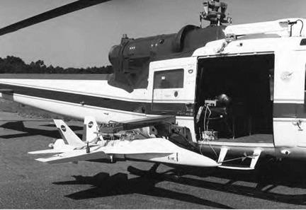
F/A-18A drop model mounted on its launch rig on a NASA helicopter in preparation for spin entry investigations at the Langley Plum Tree test site. NASA. |
years, both pilots used a single dual gun mount arrangement with a single tracker operator.
Researchers continued their search for a test site nearer to Langley, and in 1959, Langley requested and was granted approval by the Air Force to conduct drop tests at the abandoned Plum Tree bombing range near Poquoson, VA, about 5 miles from Langley. The marshy area under consideration had been cleared by the Air Force of depleted bombs and munitions left from the First and Second World War eras. A temporary building and concrete landing pad for the launch helicopter were added for operations at Plum Tree, and a surge of request jobs for U. S. high-performance military aircraft in the mid – to-late 1960s (F-14, F-15, B-1, F/A-18, etc.) brought a flurry of test activities that continued until the early 1990s.[457]
During operations at Plum Tree, the sophistication of the drop-model technique dramatically increased.[458] High-resolution video cameras were
used for tracking the model, and graphic displays were presented to a remote pilot control station, including images of the model in flight and the model’s location within the range. A high-resolution video image of the model was centrally located in front of a pilot station within a building. In addition, digital displays of parameters such as angle of attack, angle of sideslip, altitude, yaw rate, and normal acceleration were also in the pilot’s view. The centerpiece of operational capability was a digital flight control computer programmed with variable research flight control laws and a flight operations computer with telemetry downlinks and uplinks within the temporary building. NASA operations at Plum Tree lasted about 30 years and included a broad scope of free-flight model investigations of military aircraft, general aviation aircraft, parawings, gliding parachutes, and reentry vehicles. In the early 1990s, however, several issues regarding environmental protection forced NASA to close its research activities at Plum Tree and remove all its facilities. After considerable searching and consideration of several candidate sites, the NASA Wallops Flight Facility was chosen for Langley’s drop-model activities.
The last NASA drop-model tests of a military fighter for poststall studies began in 1996 and ended in 2000.[459] This project, which evaluated the spin resistance of a 22-percent-scale model of the U. S. Navy F/A-18E Super Hornet, was the final evolution of drop-model technology for Langley. Launched from a helicopter at an altitude of about
15,0 feet in the vicinity of Wallops, the Super Hornet model weighed about 1,000 pounds. Recovery of the model at the end of the flight test was again initiated with the deployment of onboard parachutes. The model used a flotation bag after water impact and was retrieved from the Atlantic Ocean by a recovery boat.
Outdoor free-flight model testing has also flourished at NASA Dryden Flight Research Center. Dryden’s primary advocate and highly successful user of free-flight models for low-speed research on advanced aerospace vehicles was the late Robert Dale Reed. An avid model builder, pilot, and researcher, Reed was inspired by his perceived need for a subscale free-flight model demonstrator of an emerging lifting body reentry configuration created by NASA Ames in 1962.[460] After initial testing of gliders of the Ames M2-F1 lifting body concept, he progressed into
|
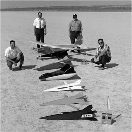
Dryden free-flight research models of reentry lifting bodies. Dale Reed, second from left, and his test team pose with the mother ship and models of the M2-F2 and the Hyper III configurations. NASA. |
the technique of using radio-controlled model tow planes to tow and release M2-F1 models. In the late 1960s, the launching technique for the unpowered models evolved with a powered radio-controlled mother ship, and by 1968, Reed’s mother ship had conducted over 120 launches. Dale Reed’s innovation and approach to using radio-controlled mother ships for launching drop models of radical configurations have endured to this day as the preferred method for small-scale free-flight activities at Dryden.
In the early 1970s, Reed’s work at Dryden expanded into a series of flight tests of powered and unpowered remotely piloted research vehicles (RPRVs). These activities, which included remote-control evaluations of subscale and full-scale test subjects, used a ground-based cockpit equipped with flight instruments and sensors typical of a representative
full-scale airplane. These projects included the Hyper III lifting body and a three-eighths-scale dynamically scaled model of the F-15. The technique used for the F-15 model consisted of air launches of the test article from a B-52 and control by a pilot in a ground cockpit outfitted with a sophisticated control system.[461] The setup featured a digital uplink capability, a ground computer, a television monitor, and a telemetry system. Initially, the F-15 model was recovered on its parachute in flight by helicopter midair snatch, but in later flights, it was landed on skids by the evaluation pilot.
NASA Ames also conducted and sponsored outdoor free-flight powered model testing in the 1970s as a result of interest in the oblique wing concept championed by Robert T. Jones. The progression of sophistication in these studies started with simple unpowered catapult-launched models at Ames, followed by cooperative powered model tests at Dryden in the 1970s and piloted flight tests of the AD-1 oblique wing demonstrator aircraft in the 1980s.[462] In the 1990s, Ames and Stanford University collaborated on potential designs for oblique wing supersonic transport designs, which led to flight tests of two free-flight models by Stanford.
Yet another historic high-speed outdoor free-flight facility was spun off Langley’s interests. In 1945, a proposal was made to develop a new NACA high-speed test range known as the Pilotless Aircraft Research Station, which would use rocket-boosted models to explore the transonic and supersonic flight regimes. The facility ultimately became known as the NACA Wallops Island Flight Test Range.[463] From 1945 through 1959, Wallops served as a rocket-model "flying wind tunnel” for researchers in Langley’s Pilotless Aircraft Research Division (PARD), which conducted vital investigations for the Nation’s emerging supersonic aircraft, especially the Century series of advanced fighters in the 1950s. Rocket – boosted models were used by the Pilotless Aircraft Research Division of the NACA’s Langley Laboratory in flight tests at Wallops to obtain valuable information on aerodynamic drag, dynamic stability, and control effectiveness at transonic conditions.


