Category AERONAUTICS

Dryden Flight Research Center

NASA Dryden has a deserved reputation as a flight research and flight­testing center of excellence. Its personnel had been technically respon­sible for flight-testing every significant high-performance aircraft since the advent of the world’s first supersonic research airplane, the Bell XS-1. When this facility first became part of the NACA, as the Muroc Flight Test Unit in the late 1940s, there was no overall engineering functional orga­nization. There was a small team attached to each test aircraft, consist­ing of a project engineer, an engineer, and "computers”—highly skilled women mathematicians. There were also three supporting groups: Flight Operations (pilots, crew chiefs, and mechanics), Instrumentation, and Maintenance. By 1954, however, the High-Speed Flight Station (as it was then called) had been organized into four divisions: Research, Flight Operations, Instrumentation, and Administrative. The Research division included three branches: Stability & Control, Loads, and Performance.

Shortly thereafter, Instrumentation became Data Systems, to include Computing and Simulation (sometimes together, sometimes separately). There were changes to the organization, mostly gradual, after that, but these essential functions were always present from that time forward.[862] There are approximately 50 people in the structures, structural dynamics, and loads disciplines.[863]

Analysis efforts at Dryden include establishing safety of flight for the aircraft tested there, flight-test and ground-test data analysis, and the development and improvement of computational methods for prediction. Commercially available codes are used when they meet the need, and in­house development is undertaken when necessary. Methods development has been conducted in the fields of general finite element analysis, reen­try problems, fatigue and structural life prediction, structural dynamics and flutter, and aeroservoelasticity.

Reentry heating has been an important problem at Dryden since the X15 program. Extensive thermal research was conducted during the NASA YF-12 flight project, which is discussed in a later section. One very significant application of thermal-structural predictive methods was the thermal modeling of the Space Shuttle orbiter, using the Lewis-developed Structural Performance and Redesign (SPAR) finite element code. Prior to first flight, the conditions of the boundary layer on various parts of the vehicle in actual reentry conditions were not known. SPAR was used to model the temperature distribution in the Shuttle structure, for three dif­ferent cases of aerodynamic heating: laminar boundary layer, turbulent boundary layer, and separated flow. Analysis was based on the space trans­portation system—trajectory 1 (STS-1) flight profile—and results were compared with temperature time histories from the first mission. The analysis showed that theflight data were best matched under the assump­tion of extensive laminar flow on the lower surface, and partial laminar flow on the upper surface. This was one piece of evidence confirming the important realization that laminar boundary layers could exist, under conditions of practical interest for hypersonic flight.[864]

Dryden has a unique thermal loads laboratory, large enough to house an SR-71 or similar-sized aircraft and heat the entire airframe to tem­peratures representative of high-speed flight conditions. This facility is used to calibrate flight instrumentation at expected temperatures and also to independently apply thermal and structural loads for the pur­pose of validating predictive methods or gaining a better understanding of the effects of each. It was built during the X15 program in the 1960s and is still in use today.

Aeroservoelastics—the interaction of air loads, flexible structures, and active control systems—has become increasingly important since the late 1970s. As active fly-by-wire control entered widespread use in high-performance aircraft, engineers at Dryden worked to integrate con­trol system modeling with finite-element structural analysis and aero­dynamic modeling. Structural Analysis Routines (STARS) and other programs were developed and improved from the 1980s through the present. Recent efforts have addressed the modeling of uncertainty and adaptive control.[865]

At Dryden, much of the technology transfer to industry comes not so much from the release of codes developed at Dryden, but from the interaction of the contractors who develop the aircraft with the techni­cal groups at Dryden who participate in the analysis and testing. Dryden has been involved, for example, in aeroservoelastic analysis of the X-29; F15s and F18s in standard and modified configurations (including phys­ical airframe modifications and/or modifications to the control laws); High Altitude Long Endurance (HALE) unpiloted vehicles, which have their own set of challenges, usually flying at lower speeds but also hav­ing longer and more flexible structures than fighter class aircraft; and many other aircraft types.

Structural Tailoring of Engine Blades (STAEBL, Glenn, 1985)

This computer program "was developed to perform engine fan blade numerical optimizations. These blade optimizations seek a minimum weight or cost design that satisfies realistic blade design constraints, by tuning one to twenty design variables. The STAEBL system has been gen­eralized to include both fan and compressor blade numerical optimiza­tions. The system analyses have been significantly improved through the inclusion of an efficient plate finite element analysis for blade stress and frequency determinations. Additionally, a finite element based approx­imate severe foreign object damage (FOD) analysis has been included. The new FOD analysis gives very accurate estimates of the full nonlinear

bird ingestion solution. Optimizations of fan and compressor blades have been performed using the system, showing significant cost and weight reductions, while comparing very favorably with refined design validation procedures.”[981]

Cooling

Hypersonics has much to say about heating, so it is no surprise that it also has something to say about cooling. Active cooling merits only slight attention, as in the earlier discussion of Dyna-Soar. Indeed, two books on Shuttle technology run for hundreds of pages and give com­plete treatments of tiles for thermal protection—but give not a word about active cooling.[1077]

What the topic of cooling mostly comprises is the use of passive cooling, which allowed the Shuttle to be built of aluminum.

During the early 1970s, when there was plenty of talk of using a liquid-fueled booster from Marshall Space Flight Center, many design­ers considered building that booster largely of aluminum. This raised the question of how bare aluminum, without protection, could serve in a Shuttle booster. It was common understanding that aluminum airframes lost strength because of aerodynamic heating at speeds beyond Mach 2, with titanium being necessary at higher speeds. But this held true for aircraft in cruise, which faced their temperatures continually. Boeing’s reusable booster was to reenter at Mach 7, matching the top speed of the X-15. Still, its thermal environment resembled a fire that does not burn the hand when one whisks it through quickly. Designers addressed the problem of heating on the vehicle’s vulnerable underside by the simple expedient of using thicker metal construction to cope with anticipated thermal loads. Even these areas were limited in extent, with the contractors noting that "the material gauges (thicknesses) required for strength exceed the minimum heat sink gauges over the majority of the vehicle.”[1078]

McDonnell-Douglas went further. In mid-1971, it introduced its own orbiter, which lowered the staging velocity to 6,200 ft/sec. Its winged booster was 82 percent aluminum heat sink. Its selected configuration was optimized from a thermal standpoint, bringing the largest savings in the weight of thermal protection.[1079] Then, in March 1972, NASA selected solid-propellant rockets for the boosters. The issue of their thermal pro­tection now went away entirely, for these big solids used steel casings that were half an inch thick and that provided heat sink very effectively.[1080]

Aluminum structure, protected by ablatives, also was in the forefront during the Precision Recovery Including Maneuvering Entry (PRIME) program. Martin Marietta, builder of the X-24A lifting body, also devel­oped the PRIME flight vehicle, the SV-5D that later was referred to as the X-23. Although it was only 7 feet in length, it faithfully duplicated the shape of the X-24, even including a small bubble-like protrusion near the front that represented the cockpit canopy.

PRIME complemented ASSET, with both programs conducting flight tests of boost-glide vehicles. However, while ASSET pushed the state of the art in materials and hot structures, PRIME used ablative thermal protection for a more straightforward design and emphasized flight performance. Accelerated to near-orbital velocities by Atlas launch vehicles, the PRIME missions called for boost-glide flight from Vandenberg Air Force Base (AFB) to locations in the western Pacific near Kwajalein Atoll. The SV-5D had higher L/D than Gemini or Apollo did, and, as with those NASA programs, it was to demonstrate preci­sion reentry. The plans called for cross range, with the vehicle flying up to 710 nautical miles to the side of a ballistic trajectory and then arriv­ing within 10 miles of its recovery point.

The piloted X-24A supersonic lifting body, used to assess the SV-5 shape’s approach and landing characteristics, was built of aluminum. The SV-5D also used this material for both its skin and primary struc­ture. It mounted both aerodynamic and reaction controls, the former consisting of right and left body-mounted flaps set well aft. Deflected symmetrically, they controlled pitch; deflected individually (asymmet­rically), they produced yaw and roll. These flaps were beryllium plates that provided a useful thermal heat sink. The fins were of steel honey­comb, likewise with surfaces of beryllium sheet.

Most of the vehicle surface obtained thermal protection from ESA 3560 HF, a flexible ablative blanket of phenolic fiberglass honeycomb that used a silicone elastomer as the filler, with fibers of nylon and silica holding the ablative char in place during reentry. ESA 5500 HF, a high – density form of this ablator, gave added protection in hotter areas. The nose cap and the beryllium flaps used a different material: carbon-phe­nolic composite. At the nose, its thickness reached 3.5 inches.[1081]

The PRIME program made three flights that took place between December 1966 and April 1967. All returned data successfully, with the third flight vehicle also being recovered. The first mission reached 25,300 ft/sec and flew 4,300 miles downrange, missing its target by only 900 feet. The vehicle executed pitch maneuvers but made no attempt at cross range. The next two flights indeed achieved cross range, respec-

Подпись: 9 Cooling
Cooling
Подпись: ALUMINUM ALLOT SKIN

CoolingFILLER BAR. NOMCI PELT

LRSI = Low Temperature Reusable Surface Insulation

HRSI = High Temperature Reusable Surface Insulation

RCG = Reaction Coated Glass

RTV = Room Temperature Vulcanizing Adhesive

INSTALLATION OF TILES ON SHUTTLE

Schematic of low – and high-temperature reusable surface insulation tiles, showing how they were bonded to the skin of the Space Shuttle. NASA.

tively of 500 and 800 miles, and the precision again was impressive. Flight 2 missed its aim point by less than 2 miles. Flight 3 missed by over 4 miles, but this still was within the allowed limit. Moreover, the terminal guidance radar had been inoperative, which probably contrib­uted to the lack of absolute accuracy.[1082]

A few years later, the Space Shuttle brought the question of whether its primary structure and skin should perhaps be built of titanium. Titanium offered a potential advantage because of its temperature resis­tance; hence, its thermal protection might be lighter. But the apparent weight saving was largely lost because of a need for extra insulation to protect the crew cabin, payload bay, and onboard systems. Aluminum could compensate for its lack of heat resistance because it had higher
thermal conductivity than titanium. It therefore could more readily spread its heat throughout the entire volume of the primary structure.

Designers expected to install RSI tiles by bonding them to the skin, and for this aluminum had a strong advantage. Both metals form thin lay­ers of oxide when exposed to air, but that of aluminum is more strongly bound. Adhesive, applied to aluminum, therefore held tightly. The bond with titanium was considerably weaker and appeared likely to fail in operational use at around 500 °F. This was not much higher than the limit for aluminum, 350 °F, which showed that the temperature resis­tance of titanium did not lend itself to operational use.[1083]

F-8 DFBW: Phase I

In implementing the DFBW F-8 program, the Flight Research Center chose to remove all the mechanical linkages and cables to the flight control surfaces, thus ensuring that the aircraft would be a pure digital fly-by-wire system from the start. The flight control surfaces would be hydraulically activated, based on electronic signals transmitted via cir­cuits that were controlled by the digital flight control system (DFCS). The F-8C’s gun bays were used to house auxiliary avionics, the Apollo Display and Keyboard (DSKY) unit,[1155] and the backup analog flight control sys­tem. The Apollo digital guidance computer, its related cooling system, and the inertial platform that also came from the Apollo program were installed in what had been the F-8C avionics equipment bay. The refer­ence information for the digital flight control system was provided by the Apollo Inertial Management System (IMS). In the conversion of the F-8 to the fly-by-wire configuration, the original F-8 hydraulic actuator slider values were replaced with specially developed secondary actua­tors. Each secondary actuator had primary and backup modes. In the primary mode, the digital computer sent analog position signals for a single actuation cylinder. The cylinder was controlled by a dual self-mon­
itoring servo valve. One valve controlled the servo; the other was used as a model for comparison. If the position values differed by a predeter­mined amount, the backup was engaged. In the backup mode, three servo cylinders were operated in a three-channel, force-summed arrangement.[1156]

Подпись: 10The triply redundant backup analog-computer-based flight control system—known as the Backup Control System (BCS)—used an indepen­dent power supply and was based on the use of three Sperry analog com­puters.[1157] In the event of loss of electrical power, 24-volt batteries could keep the BCS running for about 1 hour. Flight control was designed to revert to the BCS if any inputs from the primary digital control system to the flight control surface actuators did not match up; if the primary (digital) computer self-detected internal failures, in the event of electri­cal power loss to the primary system; and if inputs to secondary actua­tors were lost. The pilot had the ability to disengage the primary flight control system and revert to the BCS using a paddle switch mounted on the control column. The pilot could also vary the gains[1158] to the digi­tal flight control system using rotary switches in the cockpit, a valuable feature in a research aircraft intended to explore the development of a revolutionary new flight control system.

The control column, rudder pedals, and electrical trim switches from the F-8C were retained. Linear Differential Variable Transformers (LDVTs) installed in the base of the control stick were used to detect pilot control inputs. They generated electrical signals to the flight con­trol system to direct aircraft pitch and yaw changes. Pilot inputs to the rudder pedals were detected by LDVTs in the tail of the aircraft. There were two LDVTs in each aircraft control axis, one for the primary (dig­ital) flight control system and one for the BCS. The IMS supplied the flight control system with attitude, velocity, acceleration, and position change references that were compared to the pilot’s control inputs; the flight control computer would then calculate required control surface position changes to maneuver the aircraft as required.

By the end of 1971, software for the Phase I effort was well along, and the aircraft conversion was nearly complete. Extensive testing of the air­craft’s flight control systems was accomplished using the Iron Bird, and

Подпись: For the DFBW F-8 program, the Flight Research Center removed all mechanical linkages and cables to the flight control surfaces. NASA. Подпись: 10

planned test mission profiles were evaluated. On May 25, 1972, NASA test pilot Gary Krier made the first flight ever of an aircraft under dig­ital computer control, when he took off from Edwards Air Force Base. Envelope expansion flights and tests of the analog BCS followed with supersonic flight being achieved by mid-June. Problems were encoun­tered with the stability augmentation system especially, in formation flight because of the degree of attention required by the pilot to control the aircraft in the roll axis. As airspeeds approached 400 knots, control about all axes became too sensitive. Despite modifications, roll axis con­trol remained a problem with lag encountered between control stick movement and aircraft response. In September 1972, Tom McMurtry flew the aircraft, finding that the roll response was highly sensitive and could lead to lateral pilot-induced oscillations (PIOs). By May 1973, 23 flights had been completed in the Phase I DFBW program. Another seven flights were accomplished in June and July, during which differ­ent gain combinations were evaluated at various airspeeds.

In August 1973, the DFBW F-8 was modified to install an YF-16 side stick controller.[1159] It was connected to the analog BCS only. The center stick installation was retained. Initially, test flights by Gary Krier and Tom McMurtry were restricted to takeoff and landing using the center control stick, with transition to the BCS and side stick control being made at altitude. Aircraft response and handling qualities were rated as highly positive. A wide range of maneuvers, including takeoffs and landings, were accomplished by the time the side stick evaluation was completed in October 1973. The two test pilots concluded that the YF-16 side stick control scheme was feasible and easy for pilots to adapt to. This inspired high confidence in the concept and resulted in the incor­poration of the side stick controller into the YF-16 flight control design. Subsequently, four other NASA test pilots flew the aircraft using the side stick controller in the final six flights of the DFBW F-8 Phase I effort, which concluded in November 1973. Among these pilots was General Dynamics chief test pilot Phil Oestricher, who would later fly the YF-16 on its first flight in January 1974. The others were NASA test pilots William H. Dana (a former X-15 pilot), Einar K. Enevoldson, and astronaut Kenneth Mattingly. During Phase I flight-testing, the Apollo digital computer maintained its reputation for high reliability and the three-channel analog backup fly-by-wire system never had to be used.

International CCV Flight Research Efforts

As we have seen earlier, as far back as the Second World War and continuing through the 1950s and 1960s, the Europeans in particu­lar were very active in exploiting the benefits to be gained from the use of fly-by-wire flight control systems in aircraft and missile systems. Experimental fly-by-wire research aircraft programs in Europe and Japan rapidly followed, sometimes nearly paralleled, and even occa­sionally led NASA and Air Force fly-by-wire research programs, often with the assistance of U. S. flight control system companies. As with U. S. programs, foreign efforts focused on the application of digital fly-by­wire flight control systems in conjunction with modifications to existing service aircraft to create unstable CCV testbeds. Foreign CCV research efforts conclusively validated the benefits attainable from integration of digital computers into fly-by-wire flight control systems and provided experience and confidence in their use in new aircraft designs that have increasingly become multinational.

German CCV F-104G

Capitalizing on their earlier experience with analog fly-by-wire flight control research, by early 1975 the Germans had begun a flight research
program to investigate the flying qualities of a highly unstable high- performance aircraft equipped with digital flight controls. For this purpose, they modified a Luftwaffe Lockheed F-104G to incorporate a quadruplex digital flight control system. Known as the CCV F-104G, it featured a canard (consisting of another F-104G horizontal tail) mounted at a fixed negative incidence angle of 4 degrees, on the upper fuselage behind the cockpit and a large jettisonable weight carried under the aft fuselage. These features, in conjunction with internal fuel transfer, were capable of moving the aircraft’s center of gravity rearward to create a neg­ative stability margin of up to 20 percent. The CCV F-104G flew for the first time in 1977 from the German flight research center at Manching, with flight-testing of the aircraft in the canard configuration beginning in 1980. The CCV F-104G test program ended in 1984 after 176 flights.[1217]

The Continuing Legacy of FBW Research in Aircraft Development

Fly-by-wire technology developed by NASA and the Air Force served as the basis for flight control systems in several generations of military and civilian aircraft. Many of these aircraft featured highly unconven­tional airframe configurations that would have been unflyable without computer-controlled fly-by-wire systems. An interesting example was the then highly classified Lockheed Have Blue experimental stealth technology flight demonstrator. This very unusual aircraft first flew in 1977 and was used to validate the concept of using a highly faceted air­frame to provide a very low radar signature. Unstable about multiple axes, Have Blue was totally dependent on its computer-controlled fly­by-wire flight control system that was based on that used in the F-16. Its success led to the rapid development and early deployment of the stealthy Lockheed F-117 attack aircraft that first flew in 1981 and was operational in 1983.[1286] More advanced digital fly-by-wire flight control systems enabled an entirely new family of unstable, aerodynamically refined "stealth” combat aircraft to be designed and deployed. These
include the Northrop B-2 Spirit flying wing bomber and Lockheed’s F-22 Raptor and F-35 Lightning II fighters with their highly integrated digi­tal propulsion and flight control systems.

Подпись: 10Knowledge of the benefits and confidence in the use of digital fly-by­wire technology are today widespread across the international aerospace industry. Nearly all new military aircraft—including fighters, bombers, and cargo aircraft, as well as commercial airliners, both U. S. and for­eign—have reaped immense benefits from the legacy of NASA’s pioneer­ing digital fly-by-wire flight and propulsion control efforts. On the airlift side, the Air Force’s Boeing C-17 was designed with a quad-redundant digital fly-by-wire flight control system.[1287] In Europe, Airbus Industrie was an early convert to digital fly-by-wire and the increasing use of elec­tronic subsystems. All of its airliners, starting with the A320 in 1987, were designed with fully digital fly-by-wire flight control architectures along with side stick controllers.[1288] Reliance on complex and heavy hydraulic systems is being reduced as companies increase the emphasis on elec­trically powered flight controls. With this approach, both electrical and self-contained electrohydraulic actuators are controlled by the digital flight control system’s computers. The benefits are lower weight, reduced maintenance cost, the ability to provide redundant electrical power cir­cuits, and improved integration between the flight control s ystem and the aircraft’s avionics and electrical subsystems. Electric flight control technology reportedly resulted in a weight reduction of 3,300 pounds in the A380 compared with a conventional hydromechanical flight control system.[1289] Boeing introduced fly-by-wire with its 777, which was certified for commercial airline service in 1995. It has been in routine airline ser­vice with its reliable digital fly-by-wire flight control system ever since. In addition to a digital fly-by-wire flight control system, the next Boeing airliner, the 787, incorporates some electrically powered and operated flight control elements (the spoilers and horizontal stabilizers). These are designed to remain functional in the event of either total hydraulic systems failure or flight control computer failure, allowing the pilots to maintain control in pitch, roll, and yaw and safely land the aircraft.

Подпись: 10Today, the tremendous benefits made possible by the use of digital fly-by-wire in vehicle control systems have migrated into a variety of applications beyond the traditional definition of aerospace systems. As a significant example, digital fly-by-wire ship control systems are now operational in the latest U. S. Navy warships, such as the Seawolf and Virginia class submarines. NASA experts, along with those from the FAA and military and civil aviation agencies, supported the Navy in develop­ing its fly-by-wire ship control system certification program.[1290] Thus, the vision of early advocates of digital fly-by-wire technology within NASA has been fully validated. Safe and efficient, digital fly-by-wire technol­ogy is today universally accepted with its benefits available to the mil­itary services, airline travelers, and the general public on a daily basis.

High-Speed Research

When NASA decided to start a High-Speed Research (HSR) program in 1990, it quickly decided to draw in the E Cubed combustor research to address previous concerns about emissions. The goal of HSR was to develop a second generation of High-Speed Civil Transport (HSCT) air­craft with better performance than the Supersonic Transport project of the 1970s in several areas, including emissions. The project sought to lay the research foundation for industry to pursue a supersonic civil trans­port aircraft that could fly 300 passengers at more than 1,500 miles per hour, or Mach 2, crossing the Atlantic or Pacific Ocean in half the time of subsonic jets. The program had an aggressive NOx goal because there were still concerns, held over from the days of the SST in the 1970s, that a super-fast, high-flying jet could damage the ozone layer.[1414]

NASA’s Atmospheric Effects of Stratospheric Aircraft project was used to guide the development of environmental standards for the new HSCT exhaust emissions. The study yielded optimistic findings:
there would be negligible environmental impact from a fleet of 500 HSCT aircraft using advanced technology engine components.[1415] The HSR set a NOx emission index goal of 5 grams per kilogram of fuel burned, or 90 percent better than conventional technology at the time.[1416]

NASA sought to meet the NOx goal primarily through major advance­ments in combustion technologies. The HSR effort was canceled in 1999 because of budget constraints, but HSR laid the groundwork for future development of clean combustion technologies under the AST and UEET programs discussed below.

Benefits of NASA’s "Good Stewardship" Regarding the Agency’s Participation in the Federal Wind Energy Program

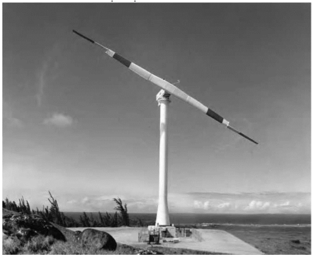
NASA Lewis’s involvement in the Federal Wind Energy Program from 1974 through 1988 brought a high degree of engineering expe­rience and expertise to the project that had a lasting impact on the development of use of wind energy both in the United States and inter­nationally. During this program, NASA developed the world’s first mul­timegawatt horizontal-axis wind turbines, the dominant wind turbine design in use throughout the world today.

NASA Lewis was able to make a quick start and contribution to the program because of the Research Center’s longstanding experi­ence and expertise in aerodynamics, power systems, materials, and structures. The first task that NASA Lewis accomplished was to bring forward and document past efforts in wind turbine development, includ­ing work undertaken by Palmer Putnam (Smith-Putnam wind tur­bine), Ulrich Hutter (Hutter-Allgaier wind turbine), and the Danish

Gedser mill. This information and database served both to get NASA Lewis involved in the Wind Energy Program and to form an initial data and experience foundation to build upon. Throughout the program, NASA Lewis continued to develop new concepts and testing and modeling techniques that gained wide use within the wind energy field. It documented the research and development efforts and made this information available for industry and others working on wind turbine development.

Подпись: 13Lasting accomplishments from NASA’s program involvement included development of the soft shell tubular tower, variable speed asynchronous generators, structural dynamics, engineering model­ing, design methods, and composite materials technology. NASA Lewis’s experience with aircraft propellers and helicopter rotors had quickly enabled the Research Center to develop and experiment with different blade designs, control systems, and materials. A significant blade development program advanced the use of steel, aluminum, wood epoxy composites, and later fiberglass composite blades that generally became the standard blade material. Finally, as presented in detail above, NASA was involved in the development, building, and testing of 13 large horizontal-axis wind turbines, with both the Mod-2 and Mod-5B turbines demonstrating the feasibility of operat­ing large wind turbines in a power network environment. With the end of the energy crisis of the 1970s and the resulting end of most U. S. Government funding, the electric power market was unable to support the investment in the new large wind turbine technology. Development interest moved toward the construction and operation of smaller wind turbine generators for niche markets that could be supported where energy costs remained high.

NASA Lewis’s involvement in the wind energy program started winding down in the early 1980s, and, by 1988, the program was basically turned over to the Department of Energy. With the decline in energy prices, U. S. turbine builders generally left the business, leaving Denmark and other European nations to develop the commercial wind turbine market.

While NASA Lewis had developed a 4-megawatt wind turbine in 1982, Denmark had developed systems with power levels only 10 per­cent of that at that time. However, with steady public policy and prod­uct development, Denmark had captured much of the $15 billion world market by 2004.

TABLE 1

COMPARATIVE WIND TURBINE TECHNOLOGICAL DEVELOPMENT, 1981 -2007

TURBINE TYPE

Nibe A

NASA WTS-4

Vestas

YEAR

1981

1982

2007

COUNTRY OF ORIGIN

Denmark

United States

Denmark

POWER (IN KW)

630

4,000

1,800

TIP HEIGHT (FEET)

230

425

355

POWER REGULATION

Partial pitch

Full pitch

Full pitch

BLADE NUMBER

3

2

3

BLADE MATERIAL

Steel/fiberglass

Fiberglass

Fiberglass

TOWER STRUCTURE

Concrete

Steel tubular

Steel tubular

Source: Larry A. Viterna, NASA.

Most of the technology developed by NASA, however, continued to represent a significant contribution to wind power generation applica­ble both to large and small wind turbine systems. In recent years, inter­est has been renewed in building larger-size wind turbines, and General Electric, which was involved in the DOE-NASA wind energy program, has now become the largest U. S. manufacture of wind power generators and, in 2007, was among world’s top three manufacturers of wind tur­bine systems. The Danish company Vestas remained the largest company in the wind turbine field. GE products currently include 1.5-, 2.5-, and, for offshore use, 3.6-megawatt systems. New companies, such as Clipper Wind Power, with its manufacturing plant in Cedar Rapids, IA, and Nordic Windpower also have entered the large turbine fabrication business in the United States. Clipper, which is a U. S.-U. K. company, installed its first system at Medicine Bow, WY, which was the location of a DOE-NASA Mod-2 unit. In the first quarter of 2007, the company installed eight com­mercial 2.5-megawatt Clipper Liberty machines. Nordic Windpower, which represents a merger of Swedish, U. S., and U. K. teams, markets its 1-megawatt unit that encompasses a two-bladed teetered rotor that evolved from the WTS-4 wind turbine under the NASA Lewis program.

In summary, NASA developed and made available to industry sig­nificant technology and turbine hardware designs through its "good stewardship” of wind energy development from 1974 through 1988. NASA thus played a leading role in the international development and utilization of wind power to help address the Nation’s energy needs today. In doing so, NASA Lewis fulfilled its primary wind program goal
of developing and transferring to industry the technology for safe, reliable, and environmentally acceptable large wind turbine systems capable of generating significant amounts electricity at cost competitive prices. In 2008, the United States achieved the No. 1 world ranking for total installed capacity of wind turbine systems for the generation of electricity.

Whitcomb and History

Aircraft manufacturers tried repeatedly to lure Whitcomb away from NASA Langley with the promise of a substantial salary. At the height of his success during the supercritical wing program, Whitcomb remarked: "What you have here is what most researchers like—independence. In private industry, there is very little chance to think ahead. You have to worry about getting that contract in 5 or 6 months.”[256] Whitcomb’s inde­pendent streak was key to his and the Agency’s success. His relationship with his immediate boss, Laurence K. Loftin, the Chief of Aerodynamic Research at Langley, facilitated that autonomy until the late 1970s. When ordered to test a laminar flow concept that he felt was impracti­cal in the 8-foot TPT, which was widely known as "Whitcomb’s tunnel,” he retired as head of the Transonic Aerodynamics Branch in February 1980. He had worked in that organization since coming to Hampton from Worcester 37 years earlier, in 1943.[257]

Whitcomb’s resignation was partly due to the outside threat to his independence, but it was also an expression of his practical belief that his work in aeronautics was finished. He was an individual in touch with major national challenges and having the willingness and ability to devise solutions to help. When he made the famous quote “We’ve done all the easy things—let’s do the hard [emphasis Whitcomb’s] ones,” he made the simple statement that his purpose was to make a difference.[258] In the early days of his career, it was national security, when an inno­vation such as the area rule was a crucial element of the Cold War ten­sions between the United States and the Soviet Union. The supercritical wing and winglets were Whitcomb’s expression of making commercial aviation and, by extension, NASA, viable in an environment shaped by world fuel shortages and a new search for economy in aviation. He was a lifelong workaholic bachelor almost singularly dedicated to subsonic aerodynamics. While Whitcomb exhibited a reserved personality outside the laboratory, it was in the wind tunnel laboratory that he was unre­strained in his pursuit of solutions that resulted from his highly intui­tive and individualistic research methods.

With his major work accomplished, Whitcomb remained at Langley as a part-time and unpaid distinguished research associate until 1991. With over 30 published technical papers, numerous formal presenta­tions, and his teaching position in the Langley graduate program, he was a valuable resource for consultation and discussion at Langley’s numer­ous technical symposiums. In his personal life, Whitcomb continued his involvement in community arts in Hampton and pursued a new quest: an alternative source of energy to displace fossil fuels.[259]

Whitcomb’s legacy is found in the airliners, transports, business jets, and military aircraft flying today that rely upon the area rule fuselage, supercritical wings, and winglets for improved efficiency. The fastest, highest-flying, and most lethal example is the U. S. Air Force’s Lockheed Martin F-22 Raptor multirole air superiority fighter. Known widely as the 21st Century Fighter, the F-22 is capable of Mach 2 and features an area rule fuselage for sustained supersonic cruise, or supercruise, per­formance and a supercritical wing. The Raptor was an outgrowth of the Advanced Tactical Fighter (ATF) program that ran from 1986 to 1991. Lockheed designers benefited greatly from NASA work in fly-by-wire control, composite materials, and stealth design to meet the mission of the new aircraft. The Raptor made its first flight in 1997, and produc­tion aircraft reached Air Force units beginning in 2005.[260]

Whitcomb’s ideal transonic transport also included an area rule fuselage, but because most transports are truly subsonic, there is no need for that design feature for today’s aircraft.[261] The Air Force’s C-17 Globemaster III transport is the most illustrative example. In the early 1990s, McDonnell-Douglas used the knowledge generated with the YC-15 to develop a system of new innovations—supercritical airfoils, winglets, advanced structures and materials, and four monstrous high-bypass tur­bofan engines—that resulted in the award of the 1994 Collier Trophy. After becoming operational in 1995, the C-17 is a crucial element in the Air Force’s global operations as a heavy-lift, air-refuelable cargo trans­port.[262] After the C-17 program, McDonnell-Douglas, which was absorbed into the Boeing Company in 1997, combined NASA-derived advanced blended wing body configurations with advanced supercritical airfoils and winglets with rudder control surfaces in the 1990s.[263]

Unfortunately, Whitcomb’s tools are in danger of disappearing. Both the 8-foot HST and the 8-foot TPT are located beside each other on Langley’s East Side, situated between Langley Air Force Base and the Back River. The National Register of Historic Places designated the Collier-winning 8-foot HST a national historic landmark in October 1985.[264] Shortly after Whitcomb’s discovery of the area rule, the NACA suspended active operations at the tunnel in 1956. As of 2006, the Historic Landmarks program designated it as "threatened,” and its future

Подпись:
disposition was unclear.[265] The 8-foot TPT opened in 1953. He validated the area rule concept and conducted his supercritical wing and wing- let research through the 1950s, 1960s, and 1970s in this tunnel, which was located right beside the old 8-foot HST. The tunnel ceased oper­ations in 1996 and has been classified as "abandoned” by NASA.[266] In the early 21st century, the need for space has overridden the historical importance of the tunnel, and it is slated for demolition.

Overall, Whitcomb and Langley shared the quest for aerody­namic efficiency, which became a legacy for both. Whitcomb flour­ished working in his tunnel, limited only by the wide boundaries of his intellect and enthusiasm. One observer considered him to be "flight

Whitcomb and History

A 3-percent scale model of the Boeing Blended Wing Body 450 passenger subsonic transport in the Langley 14 x 22 Subsonic Tunnel. NASA.

theory personified.”[267] More importantly, Whitcomb was the ultimate personification of the importance of the NACA and NASA to American aeronautics during the second aeronautical revolution. The NACA and NASA hired great people, pure and simple, in the quest to serve American aeronautics. These bright minds made up a dynamic community that created innovations and ideas that were greater than the sum of their parts. Whitcomb, as one of those parts, fostered innovations that proved to be of longstanding value to aviation.

Breaking Up Shock Waves with "Quiet Spike&quot

In June 2003, the FAA—citing a finding by the National Research Council that there were no insurmountable obstacles to building a quiet super­sonic aircraft—began seeking comments on its noise standards in advance of a technical workshop on the issue. In response, the Aerospace Industries Association, the General Aviation Manufactures Association, and most aircraft companies felt that the FAA’s sonic boom restriction

was the still the most serious impediment to creating the market for a supersonic business jet (SSBJ), which would be severely handicapped if unable to fly faster than sound over land.[511]

By the time the FAA workshop was held in mid-November, Peter Coen of the Langley Center and a Gulfstream vice president were able to report on the success of the SSBD. Coen also outlined future initia­tives in NASA’s Supersonic Vehicles Technology program. In addition to leveraging the results of DARPA’s QSP research, NASA hoped to engage industry partners for follow-on projects on the sonic boom, and was also working with Eagle Aeronautics on new three-dimensional CFD boom propagation models. For additional psychoacoustical studies, Langley had reconditioned its boom simulator booth. And as a possible followup to the SSBD, NASA was considering a shaped low-boom demonstrator that could fly over populated areas, allowing definitive surveys on pub­lic acceptance of minimized boom signatures.[512]

The Concorde made its final transatlantic flights just a week after the FAA’s workshop. Its demise marked the first time in modern his­tory that a mode of transportation had retreated back to slower speeds. This did, however, leave the future supersonic market entirely open to business jets. Although the success of the SSBD hinted at the feasibil­ity of such an aircraft, designing one—as explained in a new study by Langley’s Robert Mack—would still not be at all easy.[513]

During the next several years, a few individual investors and a number of American and European aircraft companies—including Gulfstream, Boeing, Lockheed, Cessna, Raytheon, Dassault, Sukhoi, and the privately held Aerion Corporation—pursued assorted SSBJ concepts with varying degrees of cooperation, competition, and commitment. Some of these and other aviation-related companies also worked together on supersonic strategies through three consortiums: Supersonic Aerospace International

Breaking Up Shock Waves with "Quiet Spike&quot

(SAI), which had support from Lockheed-Martin; the 10-member Supersonic Cruise Industry Alliance (SCIA); and Europe’s High-Speed Aircraft Industrial Project (HISAC), comprising more than 30 companies, universities, and other members. Meanwhile, the FAA began the lengthy process for considering a new metric on acceptable sonic booms and, in the interest of global consistency, prompted the International Civil Aviation Organization (ICAO) to also put the issue on its agenda. It was in this environment of both renewed enthusiasm and ongoing uncertainty about commercial supersonic flight that NASA continued to study and experi­ment on ways to make the sonicboom more acceptable to the public.[514]

Richard Wlezien (back from DARPA as NASA’s vehicle systems man­ager) hoped to follow up on the SSBD with a truly low-boom super-

sonic demonstrator, possibly by 2010. In July 2005, NASA announced the Sonic Boom Mitigation Project, which began with concept explorations by major aerospace companies on the feasibility of either modifying another existing aircraft or designing a new demonstrator.[515] As explained by Peter Coen, "these studies will determine whether a low sonic boom demonstra­tor can be built at an affordable cost in a reasonable amount of time.”[516] Although numerous options for using existing aircraft were under inves­tigation, most of the studies were leaning toward the need to build a new experimental airplane as the most effective solution. On August 30, 2005, however, NASA Headquarters announced the end of the short-lived Sonic Boom Mitigation Project because of changing priorities.[517]

Despite this setback, there was still one significant boom lowering experiment in the making. Gulfstream Aerospace Corporation, which had been teamed with Northrop Grumman in one of the canceled studies, had already patented a new sonic boom mitigation technique.[518] Testing this invention—a retractable lance-shaped device to extend the length of an aircraft—would become the next major sonic boom flight experiment.

In the meantime, NASA continued some relatively modest sonic boom testing at the Dryden Center, mainly to help improve simulation capabili­ties. In a joint project with the FAA and Transport Canada in the summer of 2005, researchers from Pennsylvania State University strung an array of advanced microphones at Edwards AFB to record sonic booms created by Dryden F-18s passing overhead. Eighteen volunteers, who sat on lawn chairs alongside the row of microphones during the flyovers to experience the real thing, later gauged the fidelity of the played-back recordings. These were then used to help improve the accuracy of the booms replicated in simulators.[519]

“Quiet Spike” was the name that Gulfstream gave to its nose boom concept. Based on CFD models and results from Langley’s 4 by 4 super-

Breaking Up Shock Waves with "Quiet Spike&quot

Close-up view of the SSBD F-5E, showing its enlarged "pelican” nose and lower fuselage designed to shape the shock waves from the front of the airframe. NASA.

sonic wind tunnel, Gulfstream was convinced that the Quiet Spike device could greatly mitigate a sonic boom by breaking up the typical nose shock into three less-powerful waves that would propagate in parallel to the ground.[520] However, the company needed to test the structural and aero­dynamic suitability of the device and also obtain supersonic in-flight data on its shock scattering ability. NASA’s Dryden Flight Research Center had the capabilities needed to accomplish these tasks. Under this latest public – private partnership, Gulfstream fabricated a telescoping 30-foot-long nose boom (made of molded graphite epoxy over an aluminum frame) to attach to the radar bulkhead of Dryden’s frequently modified F-15B No. 836. A motorized cable and pulley system could extend the spike up to 24 feet and retract it back to 14 feet. After extensive static testing at its Savannah, GA, facility, Gulfstream and NASA technicians at Dryden attached the specially instrumented spike to the F-15’s radar bulkhead in April 2006 and began conducting further ground tests, such as for vibration.[521]

After various safety checks, aerodynamic assessments and checkout flights, Dryden conducted Quiet Spike flight tests from August 10, 2006 until February 14, 2007. Key engineers on the project included Dryden’s Leslie Molzahn and Thomas Grindle, and Gulfstream’s Robbie Cowart. Veteran NASA test pilot Jim Smolka gradually expanded the F-15B’s flight envelope up to Mach 1.8 and performed sonic boom experiments with the telescoping nose boom at speeds up to Mach 1.4 at 40,000 feet. Aerial refueling by AFFTC’s KC-135 allowed extended missions with multiple test points. Because it was known that the weak shock waves from the spike would rather quickly coalesce with the more powerful shock waves generated by the rest of the F-15’s unmodified high-boom airframe, data were collected from distances of no more than 1,000 feet. These mea­surements, made by a chase plane using similar probing techniques to those of the SR-71 and SSBD tests, confirmed CFD models on the spike’s ability to generate a sawtooth wave pattern that, if reaching the surface, would cause only a muffled sonic boom. Analysis of the data appeared to confirm that shocks of equal strength would not coalesce into a sin­gle strong shock. In February 2007, with all major test objectives hav­ing been accomplished, the Quiet Spike F-15B was flown to Savannah for Gulfstream to restore to its normal configuration.[522]

For this successful test of an innovative design concept for a future SSBJ, James Smolka, Leslie Molzahn, and three Gulfstream employees subsequently received Aviation Week and Space Technology’s Laureate Award in Aeronautics and Propulsion. One month later, however, both the Gulfstream Corporation and the Dryden Center were saddened by the death in an airshow accident of Gerard Schkolnik, Gulfstream’s Director of Supersonic Technology Programs, who had been a Dryden employee for 15 years.[523]