AIRPLANE AND ITS ENGINES
THE AIRPLANE
The X-15 was born on October 5, 1954, when the NACA Committee on Aerodynamics finally decided on the need for a manned hypersonic research airplane. No airplane had even come close to flight at Mach 5 or higher. The Bell X-1 had achieved Mach 1, the Bell X-1A Mach 2.44, and the Bell X-2 Mach 3.2. But to greenlight the development of an airplane that could fly at Mach 7 was truly visionary. No such manned airplane had ever been designed, much less built. Normally, engineers study the previous incarnation of the plane they want to build, innovating from these earlier successful design ideas. But the X-15 was revolutionary—no “before” design even existed. The team would have to start from scratch.

 And for good reason.
|
|
|
The X-15 airplane had to be able to accelerate to Mach 7 and climb to over 250,000 feet in order to fill in the unexplored range in speeds above Mach 3.2 and altitudes above 126,200 feet, the maximum achieved by the X-2. (The Bell X-1 had reached 71,902 feet, and the Bell X-1A had reached 90,440 feet.) Like its predecessors, the X-15 would be flown out of Edwards Air Force Base, which was the only installation that had the support equipment and personnel—it was the location of the Air Force Test Pilot School—to
handle the research test flights. Moreover, because of the high landing speed of the X-15, Edwards had the only “runway” long enough for landing the airplane—essentially the whole expanse of the Muroc Dry Lake bed.
The new airplane, like the X-1 and X-2 before it, would be rocket-powered with high thrust, and it would be carried aloft in a “mother ship” to save fuel by applying the thrust at an altitude where the air density was low (hence, low drag). The X-15 would also have to carry enough fuel
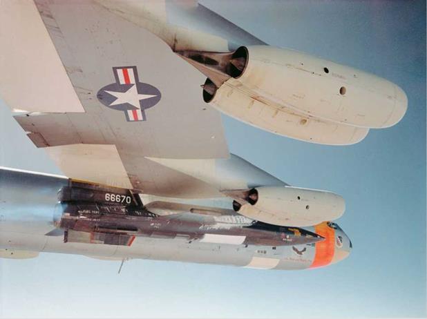
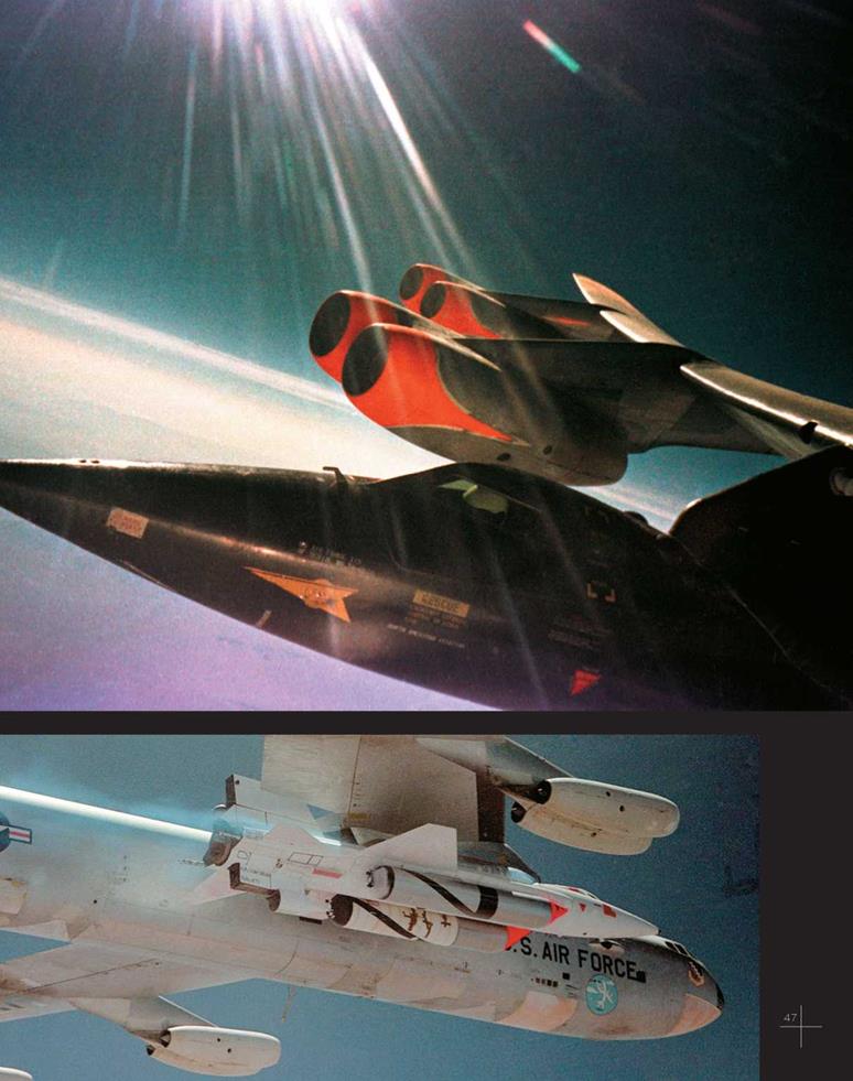
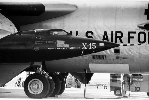
▲ X-15 under the wing of the B-52 in flight. USAF, Air Force Flight Test Center History Office, Edwards Air Force Base
▼ X-15-1 mounted under the wing of the B-52 before its first flight, June 8, 1959, with Scott Crossfield in the cockpit. USAF, Air Force Flight Test Center History Office, Edwards Air Force Base
|
![]()
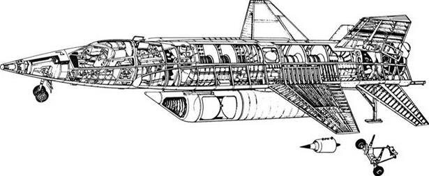
Monocoque is a French word meaning “single shell.” Here, the fuselage is a single, hollow shell that carries on its surface the aerodynamic loads exerted on the fuselage. A monocoque fuselage allows maximum space inside the fuselage for internal components, such as fuel and oxidizer tanks, and electronic equipment. A semi – monocoque structure has additional elements inside the shell, such as formers that conform to the cross-sectional shape of the fuselage and stringers that run longitudinally along the fuselage. These provide additional structural strength while still preserving volume inside the fuselage for other components. These structural elements can be seen in the cutaway view of the X-15A-2 shown on the opposite page.
to allow the high thrust to operate long enough to accelerate to the speeds and altitudes needed to perform the mission. So, the airplane had to be big enough for the fuel volume needed and be able to carry a rocket engine with far more thrust than employed previously, as well as structural materials that would maintain strength at the high temperatures to which the airplane would be subjected at its high speeds of flight.
The design also had to consider the requirements of the nonhypersonic flight regimes for the other portions of flight: It would drop from the mother ship at high subsonic speed, accelerate through Mach 1 and the transonic speed region,
then through supersonic and hypersonic flight in getting to and from the targeted data points, and finally it would have to decelerate from hypersonic flight to return to the landing site, followed by descent and landing that had to occur at relatively low subsonic conditions.
Because of these specific design requirements, the engineers started with a blank slate, using all of the latest technologies that might apply to the new airplane and the extreme conditions, known and unknown, that it would endure. They also built upon their previous experience and knowledge of the known flight regimes to design an aircraft that could unveil the mysteries of hypersonic flight.
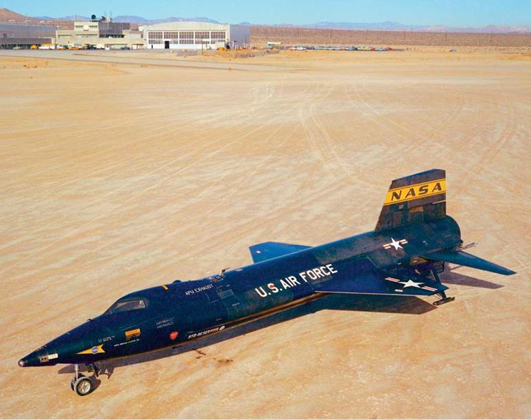
The X-15’s fuselage, wings, tail, size, and weight generally look conventional. The fuselage structure is monocoque and semimonocoque. The pilot compartment was a little more ample than that of a fighter jet. The wing has a span of 22 feet, uses an NACA 66005 symmetric laminar flow airfoil, has an area of 200 square feet and an aspect ratio of 2.5, and features a sweepback angle at the quarter chord of 25 degrees. The horizontal tail is tilted down from the fuselage, and the upper vertical tail looks like most others except that the airfoil is wedge-shaped with a blunt trailing edge, unlike the usual airfoil shapes.
But there are two major changes that further distinguish the X-15:
First, there are no ailerons on the wing; roll – control is achieved by deflecting differentially the right and left sections of the horizontal tail. Also, the horizontal tail has no elevators; instead, the whole right and left sections deflect in the same direction together to provide pitch control.
Second, the vertical tail has an unusual airfoil section. It is essentially a vertical slab, small and rounded at the leading edge and flat-sided at a 5-degree half-angle out to the trailing edge, which is blunt.
|
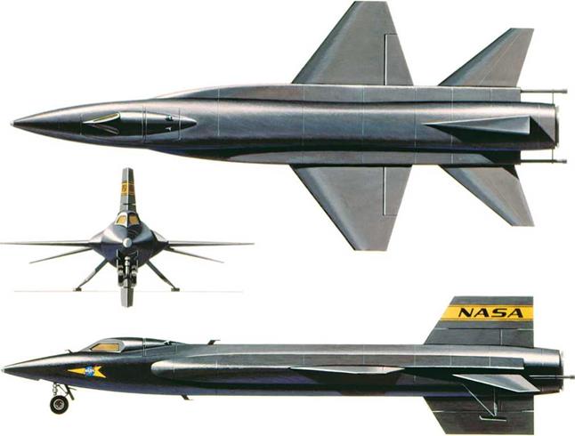
X-15 three-side view.
NASA Dryden Flight Research Center
|
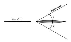
Mach waves (very weak shock waves) on a |
|
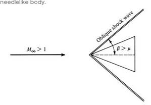
Oblique shock waves on a wedge-type body, demonstrating that the stronger shock wave is at a larger angle than the weak Mach wave. |
|
Demonstration of the constant pressure exerted on the face of the wedge, downstream of the shock wave. |
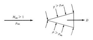
The leading edge is rounded in order to reduce the aerodynamic heating in that region. Overall, the vertical tail is a geometrically simple 10-degree total angle wedge with a blunt, flat surface for the trailing edge. The wedge shape has two aerodynamic advantages at supersonic and hypersonic speeds. First, the pressure on the flat sides is a constant downstream on the nose, and this encourages attached flow over the whole surface all the way to the blunt trailing edge. Expansion waves occur at each corner of the trailing edge. These expansion waves are the direct opposite of shock waves. The pressure decreases through an expansion wave, whereas it increases through a shock wave. The flow leaves the trailing edge through an expansion wave, and hence the pressure on the flat base of the vertical tail is lower. This in turn increases the aerodynamic drag on the vertical tail, called base drag, but at hypersonic speeds the base drag is a very small fraction of the overall drag.
The second aerodynamic advantage, and the primary reason for the use of the wedge shape, is increased directional stability. In August 1954, Charles H. McLellan, head of the 11-inch hypersonic wind tunnel at the NACA Langley Aeronautical Research Laboratory, published some stunning and almost counterintuitive results in NACA Research Memorandum LF44F21 entitled “A Method for Increasing the Effectiveness of Stabilizing Surfaces at High Supersonic Mach Numbers.” His work showed that the wedge shape “should prove many times more effective than the conventional thin shapes optimum for lower speed.”
The wedge shape took advantage of the nonlinear physics of shock waves as follows: If a surface in a supersonic flow is already inclined at an angle to the flow, say 5 degrees like the surface of a 5-degree half-angle wedge, and then the wedge itself is further inclined by an additional 2 degrees due to a control input, the pressure and hence the aerodynamic force on that surface (which is now at 7 degrees to the flow) is much higher than what would occur on a thin airfoil shape simply deflected by 2 degrees. Aerodynamicists at North American were aware of McLellan’s work, and they put this NACA

research to good use in the design of the X-15. The wedge-shaped vertical tail is clearly seen in the three-view of the X-15 (page 51). Of course, the wave drag on the tail was higher for this wedge airfoil; but the necessity for effective control authority was more important than this slight increase in drag due to the vertical tail, especially at high altitudes where the number of pounds of aerodynamic drag was small compared to the rocket engine’s high thrust of 57,000 pounds.
In spite of the wedge shape, wind tunnel tests showed that the vertical tail needed to be enlarged to have the necessary control authority. To accomplish this, a ventral tail was added below the fuselage. It was so large, however, that it would hit the ground in landing, in advance of the landing skids, which the X-15 used instead of wheels. To solve this problem, the ventral tail was split into two parts, and the lower section was made ejectable to solve the landing problem, with
|
X-15 rear view detail. X-15 nose detail. NASM NASM |
 |
 |
the drop made during approach to landing. This ejectable section was designed to be recovered and reused. However, later in flight testing, the engineers found that the lower ejectable half was not needed, and it was thus no longer used.
The pilot controls are conventional at low speeds, including launch and landing; power assist is provided on a separate control stick on the right console for use when the dynamic pressure is too great for the pilot force alone to move the control surface. But when the dynamic pressure is very low
and the control surfaces are not effective because the aerodynamic forces are too low, or these forces are nonexistent as when in space, small rocket motors with nozzles at the wing tips for roll, and at the nose and tail, help control pitch and yaw. The fuel for these motors is the monopropellant hydrogen peroxide. These rockets give the pilot control in outer space, where the aerodynamic force is zero, with the pilot using a separate control stick on the left console.
The structure is conventional, but the material affected by the external heating is Inconel X, which maintains its strength to above 2,000 degrees Fahrenheit. The support structure underneath is mostly titanium.
Speed brakes, located on the lower part of the upper vertical tail, were used for energy management to dissipate much of the energy generated by the rocket thrust in accelerating to high speed. It reduced the energy to be dissipated during the return trip to landing by increasing the drag, thus allowing a safe landing approach and touchdown. The landing gear consisted of a normal nose gear and twin metal skids instead of a conventional twin-wheeled gear, to save both weight and volume. During flight, the nose wheel

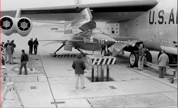
Method by which the X-15 is mated to the B-52. USAF, Air Force Flight Test Center History Office, Edwards Air Force Base
|

was stored internally, and the skids were external, flush against the fuselage.
The nose of the X-15 was round (a ball nose), which reduced the aerodynamic heating to that site. It also indicated to the pilot the angle of attack and the yaw angle at which the plane was flying, because an instrument supplied by Nortronics and installed in the nose faced into the direction of flight, supplying this information to the pilot. The nose had a spherical shape, 12 inches in diameter, and was made of Inconel X, which also helped the airplane survive the extreme heat at its nose.
Because the X-15 was designed to be air – launched, it was mounted under the right wing of a B-52 mother plane, where it was carried aloft from the ground at takeoff until dropped by the B-52 after hitching a free ride to 45,000 feet and a Mach number of 0.85. Unlike the earlier X-airplanes, with which the pilot rode to altitude in the bomber mother ship and then climbed aboard after the X-airplane checkout was complete and the liquid oxygen (LOX) was topped off (replacing what had boiled off during the climb to altitude), the test pilot was in the X-15 cabin right from the start, even before takeoff. If trouble occurred during this climb to altitude, he would have no way out unless the B-52 used its controls to drop the entire X-15 aircraft.
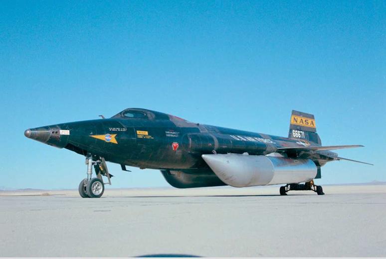
Engineers modified the third airplane, the X-15-A2, to have two external fuel tanks and an extension of 29 inches in the fuselage for equipment and instrumentation. These external fuel tanks are shown in the X-15 cutaway on page 51.
A stability augmentation system, made by Westinghouse, dampened the aerodynamic controls in all three axes. Later, the Minneapolis – Honeywell MH-96 adaptive control system replaced the SAS. These systems were necessary because analyses of the aerodynamic data indicated that the airplane would be dynamically
![]()
|
X-15-3 with ablative coating mounted under the wing of the B-52 in flight. USAF, Air Force Flight Test Center History Office, Edwards Air Force Base |
|

unstable without the system. The airplane was designed with reasonable cockpit visibility; the pilot could see all around, but he could not see the wings or the nose of the airplane.
The fuel for the later X-15 flights using the XLR99 engine was anhydrous ammonia, and the oxidizer was liquid oxygen (LOX); the fuel for the earlier flights using the XLR11 engine was water-alcohol. Both fuel and oxidizer were carried in the fuselage and held by the outside structure of the fuselage. The fuselage also contained the hydrogen peroxide (H202), used for the small control rockets that operated at high altitudes. Nitrogen pressurized the cabin, and helium pressurized the fuel and oxidizer.


