Category Soviet x-plenes

. Sukhoi 100LDU

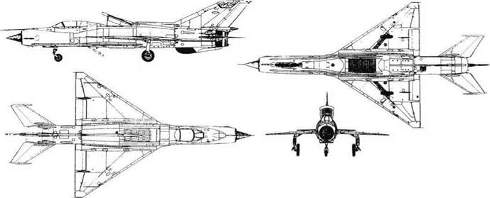
Purpose: To flight-test canard surfaces. Design Bureau: P O Sukhoi, Moscow

As explained in the history of the T-4, this enormous project required back-up research right across Soviet industry. The Sukhoi OKB
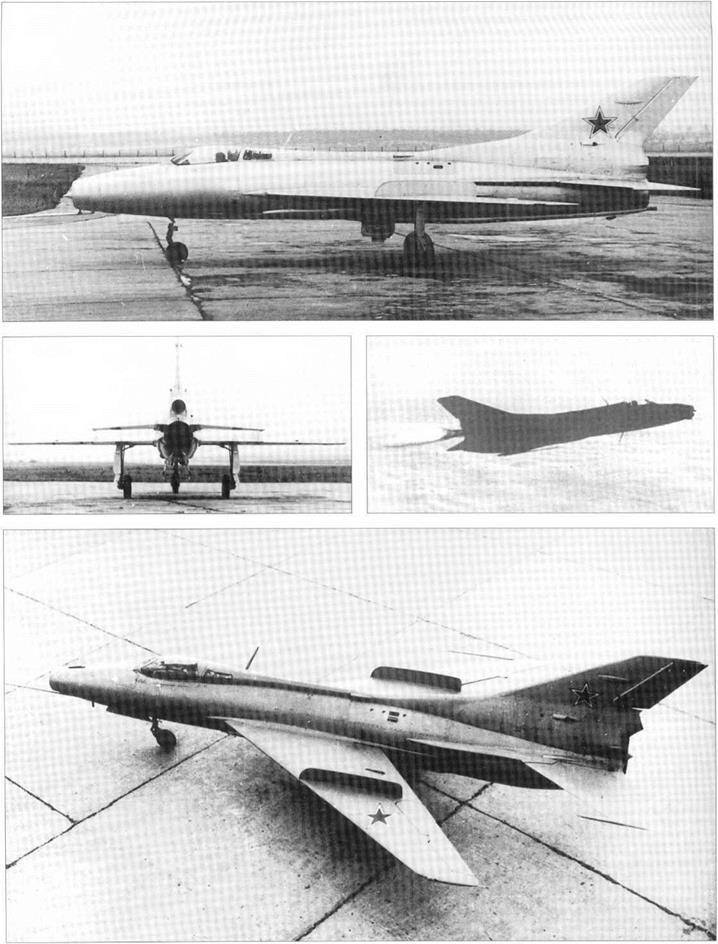
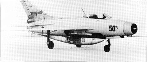
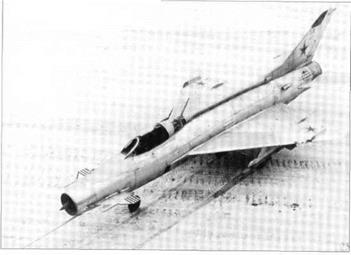
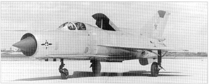
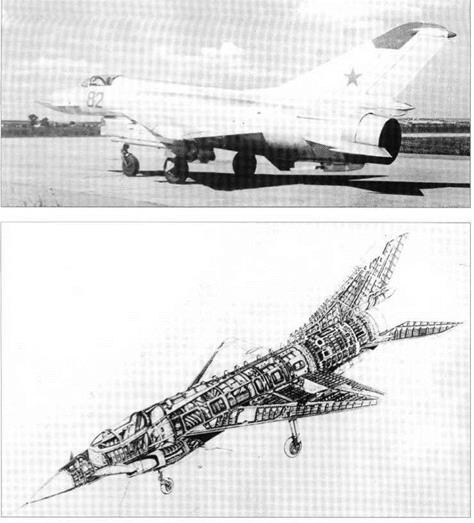
itself took on the task of investigating the proposed canard surfaces. As the only vehicle immediately available was a two-seat Su-7U, with a maximum Mach number of 2 instead of 3, the resulting aircraft – with designation 100LDU – ceased to be directly relevant to the

T-4 and became instead a general canard research vehicle. It was assigned to LIl-MAP test pilot (and future Cosmonaut) Igor Volk, and was tested in 1968-71.

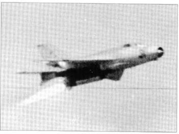
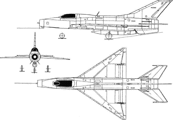
The basic Su-7U, powered by an AL-7FI – 200 with a maximum afterburning rating of 10,100kg (22,282 Ib), was subjected to minor modifications to the rudder and braking- parachute installation, and was fitted with fully powered canard surfaces on each side of the nose. These were of cropped delta shape, with a greater span and area than those of contemporary experimental MiG aircraft, and with anti-flutter rods which were longer and nearer to the tips.

This aircraft fulfilled all test objectives, though the numerical data were of only marginal assistance to the T-4/100 design team.

SLIKHOI 02-10, OR L02-10

. Sukhoi 100LDU

Purpose: To investigate direct side-force control.

Design Bureau: P O Sukhoi, Moscow.

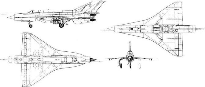
In 1969 this Su-9 was modified for the LII, which wished to investigate the application of direct side force. The LII had been concerned at American research into direct lateral or ver­tical force which could enable a fighter to rise, fall, move left or move right without changing the aircraft’s attitude. In other words such an aircraft could keep pointing at a target in front while it crabbed sideways (for example). Testing began in 1972. In 1977 the aircraft was returned to a Sukhoi OKB factory and had the upper nose fin removed, testing continuing as a joint LII/Su programme. It was further modified in 1979.

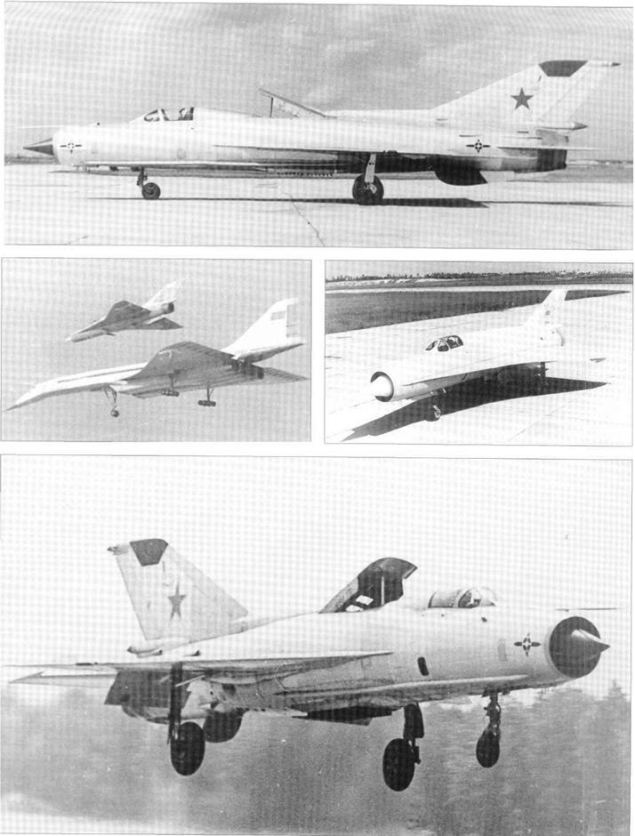
Originally this aircraft was a production Su – 9 interceptor, though it never saw active ser­vice. In its first 02-10 form is had substantial vertical fins added above and below the nose. Each fin was pivoted at mid-chord and fully
powered. The pilot was able to cut the nose fins out of his flight-control circuit, leaving them fixed at zero incidence. When they were activated, movement of his pedals drove the fins in unison with each other and in unison with the rudder. The two canard fins moved parallel to the rudder, to cause the aircraft to crab sideways. Each surface was of cropped delta shape, with a lower aspect ratio than the horizontal canards of the S-22PDS. Compared with the lower fin the upper surface had significantly greater height, and it was mounted slightly further forward. Each was fitted with an anti-flutter rod mass,
which during the course of the programme was moved from 40 per cent offin height (dis­tance from root to tip) to 70 per cent. After the 02-10’s first series of tests the upper nose fin was removed (leaving its mounting spigot still in place). Later a cine camera was installed on the fin to record lateral tracking across the ground, and in some of the later tests the wings were fitted with smoke nozzles along the leading edge, to produce visible stream­lines photographed by a camera in a box im­mediately ahead of the radio antenna.

This aircraft generated useful information, but the idea has never been put into practice.

Three different versions of L02-10 test-bed.

. Sukhoi 100LDU


Type 346

Type 346Подпись: 346A carried by B-29, front and plan views of any version except 346-3.Подпись: 346A (346D similar)Type 346Подпись: Inboard profile of 346-3Type 346

Purpose: To continue German development of a supersonic rocket aircraft.

Design Bureau: OKB-2 at Podberez’ye, lead designer Hans Rosing, in October 1948 replaced by S M Alekseyev.

On 22nd October 1946 a second group of German design engineers was formed at Pod – berez’ye to continue development of the DFS – 346 supersonic research aircraft originally designed at the DPS (German institute for glid­ing) at Griesheim near Darmstadt. Models, some made in Germany, were tested in CAHI (TsAGI) tunnels, and a North American B-25 was fitted with a mock-up nose to test the cockpit jettison system. In 1947 (date not dis­covered) the 346P (P from planer, glider) un­powered version was taken to the test airfield at Tyoplyi Stan and dropped from under the starboard wing of a captured B-29 (previously USAAF 42-6256). Amazingly, the 346P was flown not by a Russian but by Wolfgang Ziese, who had previously been chief test pilot of the Ger­man Siebel Flugzeugwerke. He had no prob­lems, and brought the glider to a normal landing. In 1948 (date not discovered) the 346­1 high-speed glider version, also known as the 346A, was released from a Tu-4 (B-29 copy) and similarly flown by Ziese to a normal landing. On 30th September 1949 the 346-2, also known as the 346D, was dropped from the B-29 and flown as a glider by Ziese even though it was fitted with rocket propulsion. No propellant was loaded, so the aircraft was much lighter than it would have been with full tanks. Despite this Ziese landed too fast and, more seriously, the landing skid failed to extend, resulting in seri­ous damage to both the aircraft and pilot. This aircraft was repaired, and in October 1950 LII pilot P I Kasmin flew it at Lukhovitsy, according to the record making a normal take-off from the runway despite having only skid landing gear. Ziese recovered, and on 13th August 1951 he flew the final aircraft of this programme, the 346-3, and fired the engines. He flew again on 2nd September, but on the third flight, on 14th September, he lost control. He managed to sep­arate the jettisonable nose from the tumbling aircraft, but this ended the programme. Later versions were abandoned. Various 346 parts were donated to the Moscow Aviation Institute.

Like its American counterpart the Bell XS-1, the 346 was an almost perfectly streamlined body with mid-mounted wings. Unlike the XS – 1, it had a prone pilot position, skid landing gear, swept wings and an extremely squat ver­tical tail with the tailplane on top. Construction was almost wholly flush-riveted light alloy. The wings had NACA-012 profile (12 per cent thick) and a sweep angle of 45° at the /4-chord line. Each wing had two shallow fences from the

Подпись: Opposite page, top: B-25 with 346 cockpit capsule. Подпись:Подпись: Above: 346-2 (346D) nose open showing pilot couch. Right: Looking down into open nose. Below: Three views of 346-2 on B-29. Type 346Подпись: Performance Max speed, intended 2,127 km/h 1,322 mph (Mach 2) in a 2 min full-power burn at high altitude No other data. Type 346leading edge to the plain flap. At the tips were inverse-tapered two-section ailerons, the inner sections being locked at high airspeeds. The elevators were similar in principle. On the 346P the tailplane, with!4-chord sweep of 35°, was fixed and surmounted by a small fixed fin. On the 346-2 and -3 the tailplane was driven by an irreversible power unit over the range -2° 407+2°. The fuselage was of circular sec­tion, with the entire nose arranged to slide forward for pilot entry and to jettison in emer­gency. The pilot lay on his stomach looking ahead through the Plexiglas nosecap, through which protruded the long instrumentation boom. Bottled gas pressure operated the flaps and retracted the skid into a ventral recess which, except for the 346P, could be faired over with twin doors. Under the tail was a small steel bumper. Unlike its predecessors, the 346-3 could be fitted with a curved skid with a levered shock strut hinged under each outer wing. These were jettisoned after take-off. The propulsion system was the Walter HWK 109- 509C, called ZhRD-109-510 in the USSR. This had two superimposed thrust chambers, one which fired continuously whenever the system was in operation, and a larger chamber used only for take-off or for brief periods when max­imum thrust was needed. The cruise chamber was rated at sea level at 300kg (661 Ib), and the main chamber at 1,700kg (3,7481b). The com­bined thrust at high altitude was about 2,250kg (4,960 Ib). Immediately behind the jettisonable nose section was a tank of concentrated hyd­rogen peroxide (called T-Stoff in Germany) while in the centre fuselage were intercon­nected tanks of methanol/hydrazine hydrate (C-Stoff). German turbopumps running on cal­cium permanganate fed the highly reactive flu­ids to the thrust chambers, where ignition was hypergolic (instantaneous).

Probably as much effort went into the 346 programme as the Americans expended on the XS-1 or D-558-II, but there was no comparison in what the programmes achieved. There is no obvious reason why these challenging aircraft, designed for Mach 2, should simply have been abandoned without even reaching Mach 1.

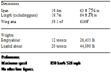
Dimensions

Span 9 m 29 ft 6% in

Length

(346-3, nose to engine nozzles) 13.447 m 44 ft IK in (instrument boom to tailplanes) 15.987 m 52 ft 3SA in Wing area (net) 14.87nf 160ft2

Weights (346-3)

Empty 3,180kg 7,01 lib

Propellants 1,900kg 4,1891b

Loaded 5,230kg ll,5301b

BICh-14

Purpose: To test an improved twin-engined ‘Parabola’.

Design Bureau: B I Cheranovskii.

In 1933 Cheranovskii schemed his first design with twin engines, the BICh-10. Later in that year he tested a tunnel model, and by 1934 he had made so many (mostly minor) changes that he redesignated it as the BICh-14. It in­terested the Central Construction Bureau, and thus received their designation CCB-10 (TsKB-10). With their assistance the aircraft was built, and the flight-test programme was opened at the end of 1934 by Yuri I Piont – kovskii. Having no slipstream, the rudder was ineffective, and it was difficult to equalise pro­
peller thrusts. On landing, with engines idling, a heavy stick force was needed to get the tail down. Though it was not one of the better BICh designs, having almost no directional stability and being extremely reluctant to re­spond to pilot inputs, it was submitted for NIl – WS testing. Here such famous pilots as Stefanovskii, Petrov and Nyukhtikov flew it, or attempted to. Various changes made this air­craft marginally acceptable, but attempts to improve it ceased in 1937 Again this was a wooden aircraft, with a skin of veneer (over the leading edge) and fabric. An innovation was to use aluminium to make the embryonic fuselage, which seat­ed up to five, and the integral fin. The wing
had four spars and 60 ribs, and was made as a centre section, of 3.3m (10ft l0in) span, and bolted outer panels. Close together on the leading edge were the two l00hp M-ll en­gines, with Townend-ring cowls, aluminium nacelles and U-2 type wooden propellers. As before, virtually all the development effort went into improving the trailing-edge con­trols, of which there were three on each wing, all hung in the usual Junkers style below the trailing edge. For most of the time the four inner surfaces were elevators and the outers ailerons, but at times the middle surfaces were tested as flaps.

The BICh-14 apparently did nothing to en­hance its designer’s reputation.

Dimensions Span Length Wing area

16.2m

6.0m

60m2

53 ft 2 in 19 ft 9 in 646ft2

Weights

Empty

1,285kg

2,833 Ib

Loaded

1,900kg

4,1891b

Performance

Maximum speed, approx

220km/h

137 mph

Range

370km

230 miles

Landing speed

70km/h

43.5 mph


BICh-14.


BICh-14BICh-14

Purpose: To attempt to fly on human muscle power.

Design Bureau: B I Cheranovskii.

Ever one to explore fresh ideas, in 1934 Cher­anovskii obtained financial support from Osoaviakhim (the Society of Friends of the Aviation and Chemical industries) for his pro­
posal to build a man-powered ornithopter (flapping-wing aircraft). It could not be made to fly.

This bird-like machine consisted mainly of a flexible wing. The pilot placed his feet on a rudder bar directly under the rudder and then bent forward between two vestigial fins until he could grasp the spade-grip which, via the
two struts seen in the photo, flapped the wings. The two struts and vertical operating rod were pivoted at the bottom to a curved landing skid.

Data not recorded.

Two views of BICh-16.

BICh-14


Grokhovskii G -31, Y akob Alksnis, Strekoza

Purpose: To build a troop-carrying glider; this was later modified into powered aircraft.

Design Bureau: WS-RKKA (Red Army special design team for aviation forces), director Pavel Ignatyevich Grokhovskii (1899-1946).

Grokhovskii had a brief but intense career, forming a branch of WS-RKKA in Leningrad in 1934 and seeing it liquidated in 1936. Most of his designs were concerned with as­sault by airborne forces, and all showed a re­markable originality. The G-61 was a ‘people pod’ able to house seven armed troops and actually flown attached under each wing of an R-5, a mass-produced 700hp biplane. The G-31 (in some documents called G-63i>/s), named for WS Gen Yakob Alksnis, was a giant cargo glider, designed by Grokhovskii and B D Urlapov to carry troops lying inside the wing. From this Grokhovskii produced the G-31 powered aircraft. First flown in late 1935, it flew to Moscow in 1936 for RKKA test­ing. It was eventually decided that the
arrangement of troops packed inside the wing, with no chance of escape in flight, was unacceptable. In any case, the concept of a powered glider for assault operations was eventually considered unsound.

Sharing a strengthened version of almost the same airframe as the glider, the G-31 (again named for Alksnis and also dubbed Strekoza, dragonfly) was a graceful aircraft as befits a powered version of a glider. Though intended for military purposes it was one of several types designed in the 1930s with no consideration of speed, because this was not thought significant. The airframe was wooden, with a vestigial fuselage of multiply veneer formed by presses with double curva­ture. On the front was a puny 100hp M-l 1 five – cylinder radial. Subsequently Grokhovskii built a G-31 with a strengthened structure matched to the 700hp M-25, an imported (later licensed) Wright R-1820 Cyclone. This was fitted in a Townend-ring cowl and it drove a Hamilton light-alloy ground-ad­justable propeller. It is believed that later a three-blade flight-variable Hamilton Standard
was fitted. As in the glider there were cockpits for a pilot and flight engineer, while between the wing ribs were compartments for 18 troops, nine in each wing (drawings show eight in each wing). They boarded and were extracted through hinged leading edges, which were transparent, as in the G-61 pods.

Few details of the G-31 have survived. Clearly the naming of this aircraft and its predecessor after Alksnis was a mistake, because he was arrested in 1936 and execut­ed in 1938. The close-knit Grokhovskii team was ‘liquidated’ very soon after the General’s arrest.

Grokhovskii G -31, Y akob Alksnis, Strekoza

Dimensions (M-25 engine)

Span

Length

Wing area

28.0m

13.9m

70.5m2

91 ft M in 45 ft 7n in 759 11!

Weights

Empty

1,400kg

3,086 Ib

Loaded

3,200kg

7,055 Ib

Performance Maximum and cruising speed limited to

135km/h

84 mph

No other data.


Left: G-31 with M-25 engine.

Below left: G-31 glider.


Below right: G-31 with M-l 1 engine.

Grokhovskii G -31, Y akob Alksnis, Strekoza


Grokhovskii G -31, Y akob Alksnis, Strekoza

Grokhovskii G -31, Y akob Alksnis, Strekoza

Lavochkin La 7R and f120Rf

Purpose: To use a rocket engine to boost a fighter’s flight performance.

Design Bureau: OKB of Semyon A Lavochkin.

By early 1944 the all-wood La-5 fighter had given way in production to the La-7, with metal spars and other modifications. The en­gine remained the ASh-82FN 14-cylinder radi­al rated at 1,600hp. One ofthe first production aircraft was fitted with an RD-1 rocket engine in order to boost its performance, especially at extreme altitudes where the ASh-82 family of engines were less impressive. The installa­tion was completed in the late autumn of 1944, and ground testing occupied nine weeks. In the last week of the year the as­signed pilot, Georgii M Shiyanov, began the flight-test programme. Together with AVDavydov the La-7R was flown 15 times without serious malfunction, though the pro-

Lavochkin La 7R and f120Rf

Above: Ground test of ‘120R’ rocket engine. Opposite: Two views of La-7R.

gramme had to be abandoned because of progressive weakening of the rear fuselage by vapour and accidental spillage of the acid. Testing was continued with the RD-lKhZ in­stalled in a second La-7R in early 1945. Brief testing was also carried out with a similar en­gine installed in the ‘120R’. On 18th August 1946 this aircraft excited spectators at the Avi­ation Day at Tushino by making a low flypast with the rocket in operation.

Both the La-7R test aircraft were originally standard production fighters. The RD-1 was one of the world’s first liquid-propellant rock­et engines to fly in a manned aircraft, the de­signer being V P Glushko. The thrust chamber was mounted on a framework of welded steel tubes carried behind a modified rear fuselage frame, which merged at the top into the fin trailing edge. To accommodate the rocket the lower part of the rudder was re­moved. In the fuselage behind the cockpit were a stainless-steel tank for 180 litres (39.6 Imperial gallons) of RFNA (concentrated red fuming nitric acid) and 90 litres (19.8 Imperi­al gallons) of kerosene. These propellants were supplied by a turbopump energised by hot gas bled from the main thrust chamber. The turbine had a governed speed of 26,000rpm, and drove pumps for the two pro­pellants plus lubricating oil and water sup­plied from a small tank to cool the turbine and thrust chamber walls. Mass of the installation was approximately 100kg (220 Ib), or 215kg (474 Ib) complete with propellants and water. The basic RD-1 had electrical ignition, while the RD-1KhZ had automatic chemical ignition from hypergolic liquids. The rocket was ofthe on/off type, cut in or out by a switch on the main throttle lever. It could not be varied in thrust (300kg, 661 Ib, at sea level), but could be shut off before the tanks were empty, nor­
mal duration being 3 to 31/2min. Both La-7R air­craft retained their armament of two UB-20 cannon. The ’ 120R’ differed in having an ASh – 83 engine, rated at 1,900hp, armament of two NS-23 guns and in other details.

Together with such other aircraft as the Pe – 2RD and Yak-3RD these test-beds confirmed the value of a rocket engine in boosting per­formance at high altitude. On the other hand they also confirmed that RFNA is not compat­ible with a wooden structure, and in any case the value of three minutes of boost was con­sidered questionable.

Dimensions (both)

Span

Length

Wing area

9.8m

8.6m

17.59m2

32 ft IK in 28 ft TM 189ft2

Weights (La-7R)

Empty

2,703kg.

5,959 Ib

Fuel and propellants

604kg

l,3321b

Loaded

3,500kg

7,716 Ib

Weights (‘120R’)

Empty

2,770kg

6,107 Ib

Fuel and propellants

470kg

l,0361b

Loaded

3,470kg

7,650 Ib

A standard La-7 typically had empty and loaded weights of 2,600kg and 3,260 kg

Performance

(La-7R) generally unchanged, but maximum speed at 6 km (19,685 ft) altitude was increased from 680 km/h (422.5 mph) to 752 km/h (467 mph).

Service ceiling was increased from 10,700 m (35,105 ft) to 13,000 m (42,651 ft).

The only figure recorded for the ‘120R’ is a speed (height unstated) of 725 km/h (450.5 mph), but this speed (at 7,400 m) is also recorded for the unboosted ‘120’.

Lavochkin La 7R and f120Rf

Lavochkin La 7R and f120RfLavochkin La 7R and f120Rf

Ye-6T/l (Ye-66A)

In 1960 the Ye-6T/l, the first true series-built MiG-21, callsign Red-31, was rebuilt for record purposes, with various modifications. In order not to reveal too much to the FAI in­ternational body, it was given the invented designation Ye-66A. The most obvious change was to attach a rocket package un­derneath the fuselage. The rocket engine was designated S-3/20M5A, the ultimate version of Dushkin’s family burning kerosene and RFNA fed by peroxide turbopumps. The propellants were packaged with the engine and control system in a large gondola designated U-21. Thrust was 3,000kg (6,614 Ib) at sea level, ris­ing to about 3,700kg (8,150 Ib) at high altitude. The rocket nozzle was angled 8° downwards, but despite this it was necessary to replace the usual MiG-21 underfin by two shorter but deeper ventral fins each inclined outwards. The main engine was replaced by an R-l 1F2- 300, with a maximum afterburning rating of 6,120kg (13,492 Ib); this engine later became standard on the MiG-21 PF. Other modifica­tions included 170 litres (37.4 Imperial gal­lons) of extra kerosene fuel in a spine fairing behind the canopy, and a fin extended for­wards to increase area of the vertical tail to 4.44m2 (47.7ft2). The Ye-66A did not set any ratified speed records, but on 28th April 1961 it was flown by G K Mosolov in a zoom to a new world absolute height record of 34,714m (113,891ft). He made a low flypast with rock­et in operation at the airshow at Moscow Tushino on Aviation Day (9th July) 1961.

Petlyakov Pe-2 experimental versions

Purpose: To test various items on modified Pe-2 aircraft.

Design Bureau: Basic aircraft, ‘100’ in special prison CCB-29 (TsKB-29), later V M Petlyakov’s own OKB.

Production of this outstanding fast tactical bomber totalled 11,427. One of the experi­mental wartime versions was the Pe-2Sh (Shturmovik, assaulter) with various combi­nations of20mm ShVAK cannon and 7.62mm ShKAS either firing ahead from a gondola or installed in one or more batteries firing obliquely down from what had been the fuse­lage bomb bay. The Pe-2VI and Pe-2VB were
special high-altitude versions with pressur­ized cabins and VK-105PD engines with two – stage superchargers. The Pe-2RD was fitted with a Dushkin/Glushko RD-1 or RD-lKhZ rocket engine installed in the tailcone, with the tanks and control system in the rear fuse­lage. This aircraft was tested in 1943 by Mark L Gallai. Like the similarly modified Tu-2, the Pe-2 Paravan (paravane) had a 5m (16ft Sin) beam projecting ahead of the nose from the tip of which strong cables led tightly back to the wingtips. While the Tu-2 had a tubular beam, that of the Pe-2 was a truss girder, and the balloon cables struck by the wires were deflected further by large wingtip rails. From
1945 one Pe-2, as well as at least one Tu-2, was used by CIAM and Factory No 51 to flight test a succession of pulsejet engines begin­ning with captured German Argus 109-014 flying-bomb units. Test engines were mount­ed above the rear fuselage, with fuel fed by pressurizing the special aircraft tank to 1.5kg/cm2 (21.31b/in2). In 1946-51, under V N Chelomey, Factory 51 improved this Ger­man pulsejet into a succession of engines designated from D-3 to D-14-4. All the early models were tested on the Pe-2, despite fatigue caused by the severe vibration.

Petlyakov Pe-2 experimental versions

Petlyakov Pe-2 experimental versions

Rear defence by aft-firing RO-82 rockets: RUB-2L dorsal and RUB-4 ventral.


Petlyakov Pe-2 experimental versionsTop left: Twin ShVAK-20 cannon in Pe-2Sh (two more were further back).

Подпись:
Right: Pe-2VI.

Sukhoi T6-1

Sukhoi T6-1

Purpose: To create a superior tactical attack bomber.

Design Bureau: P O Sukhoi, Moscow.

As noted in the story of the S-22I (S-32), publi­cation of the formidable requirements for the USAF’s TFX programme spurred a response by the USSR. These requirements called for long range with a heavy bombload and the ability to make a blind first-pass attack at su­personic speed at low level ‘under the radar’. There was obvious need to replace the IL-28 and Yak-28, and the task appeared to call for either the use of a battery of special lift en­gines or a VG (variable-geometry, ie variable- sweep) wing. Sukhoi OKB was entrusted with this important task, and took a ‘belt and braces’ approach. To get something flying quickly it decided to put VG wings on the outstanding Su-7B, resulting in the S-22I described previ­ously. For the longer term it launched devel­opment ofa new aircraft, the S-6. This was first drawn in 1963, and it was to have a fixed swept wing, two Metskvarichvili R-21F-300 en­gines each with a wet afterburning rating of 7,200kg (15,873 Ib), pilot and navigator seated in tandem, and the Puma navigation and weapon-delivery system. Five hardpoints were to carry a load of 3 tonnes (6,614 Ib), take-off weight being 20 tonnes (44,090Ib), and maximum speed was to be l,400km/h (870mph) at very low level and 2,500km/h (l,553mph, Mach 2.35) at high altitude. Short­take-off capability was to be provided by two large take-off rockets. As a cover, and to assist
in obtaining funds more quickly, the S-6 was redesignated T-58M to look like a member of that interceptor family, but in 1964 it was ter­minated. This was partly because of in – tractible problems with the engine (see MiG Ye-8), and partly because of the good progress with the T-58VD (see previous). In early 1965 the S-6 was replaced by the T-6, later written T6. This was a significantly larger and more powerful aircraft, even surpassing the F-lll, which was in production by then. After rollout it was given the callsign Red 61 and first flown by the chief test pilot, Vladimir S Ilyushin, on 2nd July 1967. It was fitted with a battery of lift jets, as in the T-58VD, and it was immediately found that (as before) these caused aerody­namic and control difficulties. In 1968 the R-27 main engines were removed and the com­plete rear fuselage and powerplant systems modified to take the Lyul’ka AL-21F engine, with a maximum afterburning rating of 11,200kg (24,691 Ib). To improve directional stability the wingtips were tilted sharply down in TSR.2 fashion, the anhedral being 72°. Large strakes were added on each side of the rear fuselage, and the airbrakes deleted. To meet the needs of radar designers the nose radome was made shorter, with no significant effect on drag, and over the years numerous flush antennas and fairings appeared. Even after the decision was taken to change the design to have high-aspect-ratio ‘ swing wing s’ the T6-1 continued testing systems and equipment. In 1974, having made over 320 test flights, it was retired to the WS Museum at Monino.

In fact, the design ofthe T6-1 had been even more strongly influenced by the British TSR.2, with a fixed-geometry delta wing of short span and large area and fitted with powerful blown flaps. Before the first aircraft, the T6-1, was built the wing was modified with the leading – edge angle reduced from 60° to 45° outboard of the flaps, ahead of the conventional ailerons. As originally built, the large fuselage housed two Khachaturov (Tumanskii KB) R – 27F2-300 engines each with a wet afterburn­ing rating of 9,690kg (21,3651b), fed by sharp-edged rectangular side inlets with an inner wall variable in angle and throat area. Downstream of the inlets the fuselage had a broad box-like form able to generate a con­siderable fraction of the required lift at super­sonic speed at low level. Ahead of the inlets was an oval-section forward fuselage housing two K-36D seats side-by-side, as in the F-lll, an arrangement which was considered an ad­vantage in a first-pass attack and also to assist conversion training in a dual version. There were left and right canopies each hinged up­ward from the broad spine downstream. The width of the cockpit left enough space be­tween the engine ducts for a considerable fuel tankage as well as two pairs of RD-36-35 lift jets, installed in a single row as in the T-58VD. No attempt was made to bleed any engines to provide air for reaction-jet controls, because the T6-1 was not designed to be airborne at low airspeeds. The one-piece tailplanes were in fact tailerons, driven individually by KAU – 125 power units to provide control in roll as well as pitch. For operation from unpaved strips the levered-suspension main landing gears had twin wheels with tyres 900 x 230mm, retracting forwards into bays under the air ducts, while the steerable nose gear again had twin wheels, 600 x 200mm, with mudguards, retracting to the rear. At the ex­treme tail an airbrake was provided on each side, requiring a cutaway inboard trailing edge to the tailplanes, and between the jet nozzles under the rudder was a cruciform braking parachute. For the first time the avion­ics were regarded as a PNK, a totally integrat­ed navigation and attack ‘complex’, and the T6-1 played a major role in developing this. It was fitted with four wing pylons with inter­faces for a wide range of stores, as well as two hardpoints inboard of the main-gear bays, the maximum bombload being 5 tonnes (ll,0201b). The production Su-24 has eight hardpoints for loads up to 8 tonnes (17,637 Ib).

The T6-1 was a stepping-stone to a family of powerful and formidable aircraft which in 2000 are still in service with Russia and Ukraine. Unquestionably, the liftjets were not worth having.

Sukhoi T6-1

Sukhoi T6-1

Sukhoi T6-1Sukhoi T6-1Sukhoi T6-1Sukhoi T6-1

Подпись: T10-1 as built Подпись: DOD~TT

Sukhoi T6-1Purpose: To create a superior heavy fighter. Design Bureau: P O Sukhoi, Moscow.

In 1969 the IA-PVO, the manned interceptor defence force, issued a requirement for a to­tally new heavy interceptor. This was needed to replace the Tu-128, Yak-28P and Su-15 in defending the USSR against various cruise missiles, as well as the F-l 11 and other new Western fighters and tactical aircraft. A spe­cific requirement was to combine long-range standoff-kill capability with performance and combat agility superior in a close dogfight to any Western aircraft. The formal competition was opened in 1971. Though Mikoyan and Yakovlev were invited to participate, all the running was made by Sukhoi OKB, which was eager to move on from the T-4 and get a new production aircraft. With Sukhoi himself semi-retired, Yevgenii Ivanov was appointed chief designer, with Oleg Samolovich deputy. Sukhoi’s two rival OKBs made proposals, but did not receive contracts to construct proto­type aircraft to meet this requirement (though the standoff-kill demand was also addressed by the later M1G-25P variants and MiG-31).

Sukhoi submitted two alternative proposals. Both were broadly conventional single-seat twin-engined aircraft with ‘ogival Gothic’ wings (almost delta-shape but with a double­curved leading edge) and horizontal tails, the only new feature being twin vertical tails. One had side air inlets with horizontal ramps, while the other proposal had a fuselage blended into a wing mounted underneath and two complete propulsion systems mounted under the wing. A detail was that both had outstanding pilot view with a drooped nose and bulged canopy. As the wing was more akin to a delta than to a swept wing the project was given the designation T-l 0 in the T series (see T-3). The competitive design review was won by Sukhoi in May 1972. CAHI (TsAGI) had tunnel-tested T-10 models from 1969, and the work built up each year until 1974, demanding more tunnel test­ing than any previous Soviet aircraft except the Tu-144. It was the unconventional config­uration that was chosen, with the fuselage tapering to nothing above the wing and being replaced by large engine gondolas under­neath. Drawings for the first prototype, the

T10-1, were issued in 1975. Construction was handled by the OKB factory, except for wing and tail surfaces which were made at the OKB’s associated huge production facility named for Cosmonaut Yuri Gagarin at Komsomolsk-na-Amur in Siberia. Vladimir Ilyushin began a successful flight-test pro­gramme on 20th May 1977. Investigation of basic handling, including high-AOA (angle of attack) flight, was completed in 38 flights by late January 1978. Four wing fences were added, together with anti-flutter rods on the fins and tailplanes. Many further flights ex­plored the FEW (fly-by-wire) flight controls and, after fitting no fewer than seven hard – points where pylons could be attached, the weapons control system. Red 10 was finally put on display in the Monino Museum. T10-2 began flying at the beginning of 1978, but a software error led to unexplored resonance which caused inflight breakup, killing Evgeny Solov’yov. By 1978 the OKB was busy with T10-3, the first prototype fitted with the defin­itive engine, and this was flown by Ilyushin on 23rd August 1979. In 1982 T10-3 was flown by OKB pilot Nikolai Sadovnikov from a simulated

Подпись: T10-1 after modernization.

aircraft-carrier ramp, and it later made hook – equipped simulated carrier landings. T10-4, first flown by Ilyushin on 31st October 1979, tested the new engines and avionics. So great was the need to test avionics that the Komso – molsk factory was contracted to build five further prototypes. These were designated T10-5, -6, -9, -10 and -11 (T10-7 and -8 were significantly modified). These additional pro­totypes were generally similar to T10-3, apart from the fact that the fins were canted out­wards. The T10-5 flew in June 1980, and the remainder were all on flight test by autumn 1982. Pavel Sukhoi died on 15th September 1975, and was succeeded as General Con­structor by Mikhail P Simonov. Soon after he took over, the first detailed information on the McDonnell Douglas F-15 became available. Computer simulations found that the T-10 did not meet the requirement that it should be demonstrably superior to the USAF aircraft. Simonov ordered what amounted to a fresh start, telling the author ‘We kept the wheels and ejection-seat’. Designated T-10S, from Seriynii, production, the new fighter can only be described as brilliant. Ever since the first pre-series example, the T10-17, was flown by Ilyushin on 20th April 1981 it has been the yardstick against which other fighters are judged. An enormous effort was made by Nil using T10-17 and T10-22 to clear the re­designed aircraft for production. The first true series aircraft, designated Su-27, was flown at Komsomolsk in November 1982.

The T-10 wing had 0° dihedral, and a sym­metric profile with a ruling thickness/chord ratio of 3.5 per cent, rising to 5 per cent at the root. The leading edge was fixed. It left the fuselage with a sharp radius and with a sweep angle of 79°, curving round to 41° over the outer panels and then curving back to Kiichemann tips. The main torsion box had three spars and one-piece machined skins. Most of the interior was pressurized and formed an integral tank, while high-strength ribs carried armament suspension points. The oval-section fuselage forward section was designed to accommodate the intended large radar, followed by the cockpit with a sliding canopy. Behind this came an equip­ment bay, followed by a humpbacked ‘forecastle tank’ and then a broad wing cen­tre-section tank which could be considered as part of both the wing and fuselage. A fur­ther tank was placed in the keel beam be­tween the engines. The latter were of the Lyul’ka AL-21F-3 type, each with an after­burning rating of 11,200kg (24,691 Ib). Each was placed in a large nacelle or gondola under the wing, tilted outward because of the inboard wing’s sharp taper in thickness. Each engine air duct was fed by a wedge inlet be­hind the leading edge, standing well away under the wing’s underskin to avoid swallow­
ing boundary-layer air. Each inlet contained a variable upper ramp, with auxiliary side inlets for use on take-off, and a curved lower por­tion. The large engine gondolas provided strong bulkheads on which were mounted the two vertical fins and the tailplanes. The AL-21 had its accessories mounted on top, and the massive structure and fins immedi­ately above made access difficult. From the third aircraft the engine was the Lyul’ka AL-31F, which had been specially designed for this aircraft. It had an afterburning rating of 12,500kg (27,557 Ib), and offered several other advantages, one being that it was half a tonne (1,100 Ib) lighter than the AL-21F. It had its accessories partly underneath and partly far forward on top, and the vertical tails were moved outboard away from the engine com­partments. The main landing gears had large (1,030 x 350mm) tyres on single legs and re­tracted forwards, rotating the wheel through 90° to lie flat in the root of the wing in a bay closed by side doors and large front doors which served as airbrakes. The tall nose gear had a single unbraked wheel with a 680 x 260mm tyre. It retracted backwards, and was fitted with an all-round mudguard to protect the engine inlets. The main-wheel wells re­quired a thick inboard section of the wing ad­jacent to the engine gondolas, and this was carried to the rear to provide strong beams to which the tailplanes (and in the redesigned aircraft the fins) were pivoted. The T-10 flight controls comprised conventional ailerons, two rudders and the independently con­trolled tailplanes. All these surfaces were dri­ven by power units each served by both the completely separated 210kg/cm2 (2,987 lb/in2) hydraulic systems. These systems also drove the plain flaps, landing gears (with indepen­dent airbrake actuation), nosewheel steering,
engine inlets and mainwheel brakes. The fly­by-wire system governed pitch control by the tailplanes used in unison, and provided three – axis stabilization. The mechanical controls worked directly by the pilot’s linkages to the surface power units governed the ailerons and rudder. The five internal fuel tanks were automatically controlled to supply fuel with­out disturbing the aircraft centre of gravity. A special oxygen system was provided to en­sure engine restart and afterburner light-up at high altitude. T10-1 was built with no provi­sion for armament, but in its modified state it had seven hardpoints on which external stores could be suspended.

Despite the fact that the basic aircraft had to be completely redesigned, the T-10 family of prototypes were stepping stones to the greatest fighter of the modern era.

Dimensions (T10-1 as built)

Span

Length

Wing area

14.7m 19.65m 59.0 nf

48 ft 2V, ill 64 ft 5K in

635 a2

Weights

Weight empty

18,200kg

40,123 Ib

Loaded

25,740kg

56,746 Ib

Performance

Max speed at sea level,

l,400km/h

870 mph (Mach 1.145)

at high altitude;

2,230 km/h

1,386 mph (Mach 2.1)

Service ceiling

17,500m

57,415ft

Range

3,100km

1,926 miles

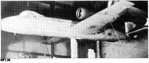
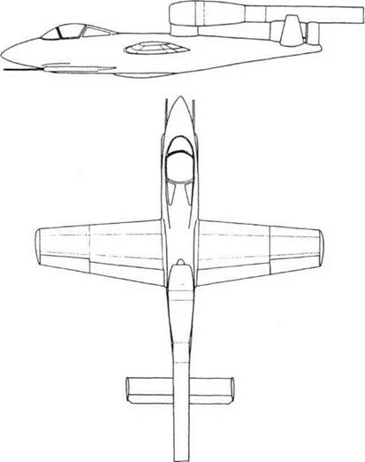
EF 126

Подпись: EF126 EF 126EF 126

Purpose: Experimental ground-attack aircraft.

Design Bureau: OKB-1, formed of German engineers led by Dipl-Ing Brunolf Baade, at Podberez’ye.

In November 1944 beleaguered German de­sign teams worked round the clock with ‘crash’ programmes intended to meet an RLM (Reich Air Ministry) specification for a minia­ture fighter designed to produce effective last – ditch defence. At the Junkers company the most important proposal was the EF (En- twicklungs Flugzeug, development aircraft) 126, code-named Elli. This was to be a small fighter powered by one of the Argus pulsejets already in mass-production for the Fi 103 flying bomb. Messerschmitt already had such an air­craft, the Me 328, powered by two of these units, testing of which showed that the violent vibration of the engines had a severe effect on the airframe and pilot. The EF 126 was small­er, almost a copy ofthe FilOSR Reichenberg, the piloted version of the flying bomb. In late 1944 it was decided that, because of poor pulsejet performance at altitude, the mission should be changed to ground attack. Despite frantic work little hardware appeared before Germany collapsed. A German three-view has been found bearing the date 9th May 1945, the day after the final surrender! Moreover, the span quoted (6.35m) is different from that given in other early-May documents, showing that the design was still fluid. Indicative of the panic environment, the data panel on this drawing gives the length as 8.9m while the drawing itself gives the same length as that below! Despite this, and the primitive nature of the project, the EF 126 was snapped up by the Russians. In October 1945 the Soviet MAP (ministry of aviation industry) organised the Junkers workers into an EF 126 cell at Dessau, headed by Prof Brunolf Baade. The intention was that this group would be moved to the USSR, but the EF 126 cell remained at Dessau while the much larger group working on jet bombers formed OKB-1 at Podberez’ye (see next entries). By January 1946 an engineering mockup had been built and parts for five air­craft produced. The EF 126 VI (first prototype) was ready in May 1946, and flight testing opened on 12th May with the VI towed as a glider behind a Ju 88. The pilot was Mathis and the tug pilot Schreiber. The EF 126 was cast off and made a normal landing. However, on 21st May Mathis was killed, after he had misjudged his glide approach, bounced hard on the rear skid, rolled to the right and cartwheeled. MAP granted permission for the resumption of test-

Top.- EF 126 in wind tunnel.

EF 126/EF 131

ing in July, after modification of the leading edge. The new pilot, Huelge, was pleased by the modified aircraft, which by this time was making rocket take-offs from a ramp. The new pulsejet engine caused problems, take-off rockets ran out, and an MAP commission headed by A S Yakovlev rejected the EF 126 as an operational vehicle because of ‘weak ar­mament, absence of armour and insufficient fuel…’ It gave permission for work to continue to help develop the engine, ramp launch and skid landing. In September 1946 V2, V3 and V4 were sent to LII (today called Zhukovskii), sup­ported by 18 specialists headed by Ing. Bessel. Further delays were caused by design changes, but gliding flights after a tow by Ju 88 resumed with V5 on 16th March 1947. The MAP directive that three aircraft should take part in the Tushino display came to nothing, but by the end ofthe year V3 and V5 had made 12 short flights, five ofthem under power. The Jumo 226 engine made 44 test flights slung under a Ju 88, but predictably the whole pro­gramme was cancelled at the start of 1948.

The EF126 resembled the FilOS flying bomb in many respects, except that instead of a war­head the nose contained the cockpit, the wings had 3° dihedral (and like some flying bombs were made of wood) and housed fuel tanks, and skid landing gear was fitted (the original Junkers drawings showed retractable tricycle gear). One drawing shows a single large retractable skid, but the prototypes had two small skids in tandem. The wing was fitted with pneumatically driven flaps, and a braking parachute was housed in the rear fuselage. The original intention was to have twin fins. EF 126 VI was fitted with the standard flying – bomb engine, the Argus 109-014 rated at 350kg (772 Ib) thrust at sea level. All subsequent air­craft had the 109-044, which Junkers took over as the Jumo 226, rated at 500kg (1,102 Ib). De­spite prolonged testing this suffered from diffi­cult ignition, poor combustion and dangerous fires. Three tanks housed 1,320 litres (290 Im­perial gallons) of fuel, fed by air pressure. Ramp take-off was by two solid motors each with an impulse of 12,000kg-seconds. Arma­ment comprised two MG 151/20, each with 180 rounds, plus an underwing load of two AB 250 containers, each housing 108 SD2 ‘butter­fly bombs’, or 12 Panzerblitz hollow-charge bomblets.

A good idea for a last-ditch weapon was un­likely to survive in the post-war era of rapid technical development.

Dimensions (V5)

Span

Length

(fuselage only) Wing area

6.65m 8.5m 7.8m 8.9 nf

21 ft 9% in 27 ft 10% in 25 ft 7 in 95.8ft2

Weights

Empty

1,100kg

2,425 Ib

Loaded

2,800 kg

6,173 Ib

Performance

Maximum speed (clean)

780km/h

485 mph

(external load)

680 km/h

423 mph

Range/endurance

(full power) 300 km

23min

(186 miles)

(60% power) 350 km

45min

(2 17 miles)

Soviet x-plenes

Introduction

F

or over 70 years from 1918 the world’s largest country was tightly controlled by a tiny group of elderly men in The Kremlin, in Moscow. Their power was absolute. They could take giant decisions, and so could make giant mistakes. They also sometimes found they had to choose between diametri­cally opposed objectives. While on the one hand aviation was a marvellous instrument for propaganda, trumpeting the achieve­ments of the Soviet Union, the underlying theme of Soviet society was of rigid secrecy.

Thus, when The Great Patriotic War began on 22nd June 1941 the outside world knew very little about Soviet aircraft. The knowledge was confined largely to the mass-produced Polikarpov biplane fighters and Tupolev monoplane bombers, and to the ANT-25 monoplane designed to break world distance records. Only very gradually did it become apparent that the austere and sombre Land of the Soviets (this was the name of a record­breaking bomber) was home to an incredible diversity of aircraft.

Other countries – the USA, France, Britain, Italy and increasingly Germany – had numer­ous aircraft companies from which flowed many hundreds of different types of aircraft. They also had individuals who sometimes managed to create aircraft and even form tiny companies, but the aircraft were invariably conventional lightplanes aimed at the private owner. Few people in what became called The West’ would have dreamed that in Stal­in’s realm individuals could even set their sights on high-powered fast aircraft bristling with strange ideas.

At the same time, the Soviet Union was far from being the earthly paradise that was orig­inally intended. It is said that power corrupts, and the record shows that anyone who ‘stuck his head above the parapet’ was likely to get it cut off. It seems incredible that in 1936-40 Stalin should have been able to unleash what was called The Terror, in which anyone who might have posed the slightest threat – for ex­ample, any senior officer in any of the armed forces – was simply put through a show trial on invented charges and shot.

In the aircraft industry, time after time peo­ple who made mistakes, or in some way fell foul of someone more senior, were simply dismissed or even imprisoned (and in a few cases, executed). It is beyond question that this omnipresent air of repression did much to counter the natural enthusiasm of count­less workers who longed for their country to be the greatest on Earth, and a leader in ad­vanced technology. When one reads what happened it seems remarkable that so many diverse aircraft actually got built.

This book is the most comprehensive at­tempt yet to collect the stories of the more important of these X-Planes (experimental aircraft) into one volume. Of course, some of the strange flying machines featured were built after the collapse of the Soviet Union, but we did not want a ponderous title. Translation of the Communist state into an intensely capitalist one has tended to concentrate the mind wonderfully. Whereas 60 years ago Soviet designers could obtain funds for often bizarre ideas which a hard-nosed financial director would have considered an almost
certain non-starter, today Ivan at his modern keyboard and screen knows that if he gets it wrong his shaky firm will go out of business.

Ironically, instead ofbeing a closely guard­ed secret, the experimental aircraft and pro­jects of the Soviet Union are today better documented than those of many Western companies. The process of rationalization has seen almost all the famous names of the aircraft industries of the UK, USA and France disappear. In many cases, and especially in the UK, their irreplaceable archives have been wantonly destroyed, as being of no in­terest to current business. We may never know what strange things their designers drew on paper but never saw built. In con­trast, the Soviet Union never destroyed any­thing, unless there was a political reason for doing so. Accordingly, though this book con­centrates on hardware, it also includes many projects which were built but never flew, and even a few which never got off the proverbial drawing board.

As in several previous books, Yefim Gordon provided much information and most of the illustrations while Bill Gunston wrote the text and put the package together. The in-flight photograph of the MiG 1.44 featured on the jacket is from a Mikoyan video. A special vote of thanks is due to Nigel Eastaway and the Russian Aviation Research Trust who provid­ed the remainder of the visual images.

Sukhoi S-37 experimental fighter.

Soviet x-plenes