Category Soviet x-plenes

BICh-17

Purpose: Single-seat fighter.

Design bureau: USP (Control of Special Work) organised by I B Kurchevskii, to which Cheranovskii was invited.

Kurchevskii was the designer of a family of APK and DRP recoilless guns of large calibre (45, 76.2, 80 and 100mm). These operated by firing a projectile down the barrel and a near­ly equal mass plus gun gas from a rear nozzle. Fighters fitted with such guns included the

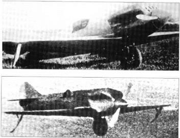
Grigorovich I-Z and Tupolev ANT-29 and ANT – 46. Cheranovskii completed the design of the BICh-17 in 1935, but in February 1936 Kurchevskii was arrested and his design bu­reau ‘liquidated’. By this time the BICh-17 was ’60 per cent complete’.

BICh-17


BICh-17

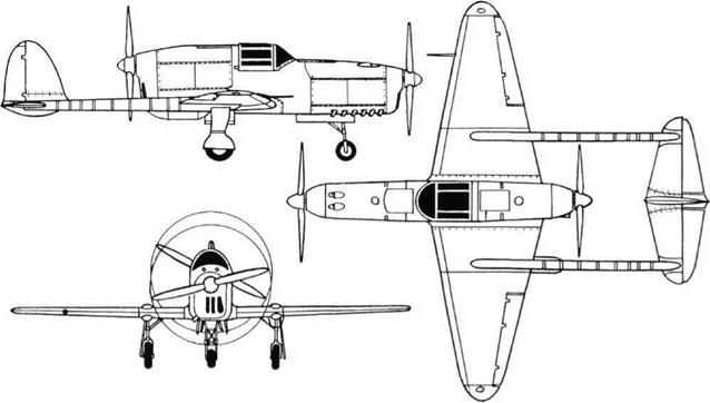
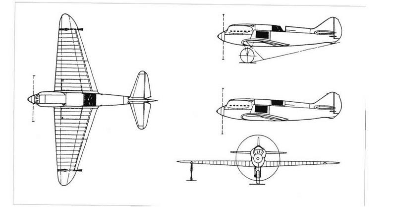
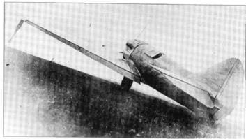
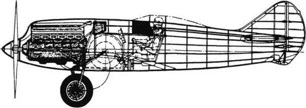
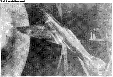
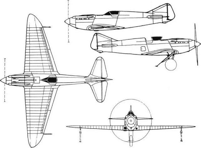
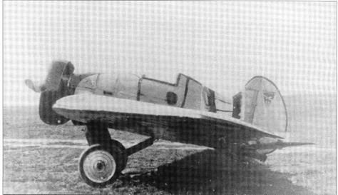
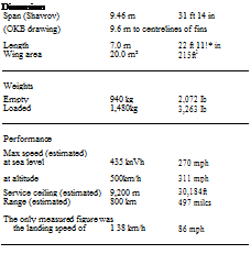
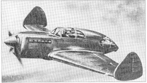
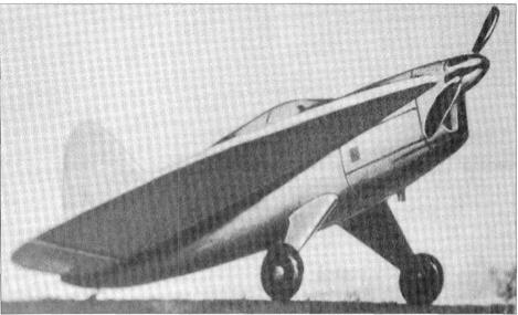
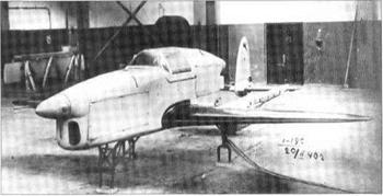
Подпись: ModelofBICh-17. BICh-17No detailed documentation on this fighter survives, but the drawing shows that it was a typical Cheranovskii ‘parabola’ design. The structure was wood, with skins of birch shpon (multi-ply veneer), the wing having detachable outer panels. The engine was a 480hp M-22 (imported or licence-made Bristol Jupiter) driving a two-blade propeller. The main landing gears retracted, probably inwards, and the elevators were divided into inner and outer sections by the two 80mm APK guns. The pilot sat under a typical Cheranovskii upward-hinged canopy which formed the front part of the fin. Aircraft left incomplete.

Grokhovskii G-37, ULK

Purpose: ‘Universal flying wing’.

Design Bureau: WS-RKKA Leningrad, Chief Designer Vladimir Rentel.

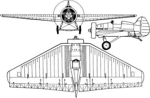
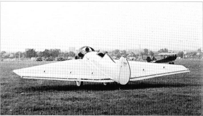
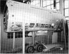
The numbering of’Grokhovskii’ aircraft is dif­ficult to interpret, and this aircraft preceded the G-31. The concept was that of a versatile aircraft for airborne assault, but it was soon evident that a Universalnoye Letayushchyeye Krylo, universal flying wing, would have wide commercial appeal. Construction was as­signed to Vladimir Rentel, who had the air­craft built in Grebno (rowing) port, Leningrad. It was taken to the airfield where from No­vember 1935 it was tested by VPChkalov, who was impressed. He later flew it to Moscow in 2hrs SOmin (average 250km/h, 155mph, which Shavrov says was ‘almost a record’). The G-37 was used for a long series of tests, including dropping of heavy loads.

The G-37 was a remarkably capable early example of an aeroplane designed to lift a de­tachable payload container (later types in­
cluded the Fi333, Miles M.68 and Fairchild XC-120). To save time the wing was that of an ANT-9 (PS-9), made of Kolchug duralumin with mainly corrugated dural skin, though the ailerons did not project beyond the wing tips. It is possible this wing came from a crashed PS-9 along with the 680hp BMW VI water – cooled V-12 engines, though these were in a different installation. The engine cowls were extended down into large trousers over the main landing gears, which contained the en­gine-cooling radiators. At the rear they extend­ed into tail booms, all these structures being of light alloy. Each boom had a tailwheel, and the twin-finned tail was duralumin with fabric cov­ering. On the centreline the wing was expand­ed into a small nacelle for the pilot and engineer. The underside of the centre wing was provided with attachments for a standard pre-loaded payload container, though no pho­tographs have been found with this in place. The completed G-37 was painted with gay stripes and stylized red stars and slogans.

There seems little doubt that this was an excellent and potentially versatile aircraft, and it is not known why it was never ordered for military or civil use.

Dimensions

Span

22.5m

73ft93/4in

(possibly for a develops:d version,

Shavrov cites)

23.7m

77 ft 9/4 ill

Length

13.85m

45 ft 5% in

(Shavrov)

16.0m

52 ft 6 in

Wing area

84.0m2

904 ft2

Weights

Empty

3,100kg

6,834 Ib

Loaded

5,700kg

12,566 Ib

Performance

Max speed at sea level

235km/h

146 mph

at 2,500m (8,200ft)

285 km/h

177 mph

Cruising speed at

2,500m (8,200 ft)

250 km/h

155 mph

Time to climb to 6 km

16min

(19,685ft)

Service ceiling

6,500 m

21,325ft

Landing speed

90 km/h

56 mph

Grokhovskii G-37, ULK

Three views of G-37 without payload container.


Grokhovskii G-37, ULKGrokhovskii G-37, ULK

Lavochkin ’164’ (La-126PVRD) and ’138’ (130PVRD-430)

Purpose: To test the use of ramjets to boost propulsion of a fighter.

Design Bureau: The OKB of S A Lavochkin.

By 1942 M M Bondaryuk had achieved reli­able operation with the VRD-430. By this time this refined subsonic ramjet had flown over 200 times on test-bed aircraft. In early 1946 two were attached under the wings of’ 126′, a slightly modified La-7, to produce the La – 126PVRD, given the OKB number ‘164’. The assigned pilot was A V Davidov, and he tested this aircraft between June and September 1946.

The VRD-430 was a simple ramjet designed for subsonic operation. It was made mainly of steel, and had a diameter of400mm (1ft 3%in).

Able to burn almost any thin hydrocarbon fuel, including high-octane petrol (gasoline), it had a thrust in the region of 300kg (661 Ib), but performance data for this engine have not been found, neither have details of its fuel and control system. The La-126 was based on the La-7 but had a completely metal stressed – skin airframe, a new wing of so-called lami­nar profile, a modified canopy and many other changes, including the devastating ar­mament of four NS-23 guns firing projectiles with more than twice the mass of the 20mm ShVAK. The La-138 was basically an La-9 fighter, in which the new wing and armament of the La-126 were matched with a com­pletely redesigned fuselage. As before, a VRD-430 ramjet was hung under each wing,
to produce the ‘164’. The ‘138’ was the desig­nation of the ‘130’ after it had been fitted with two VRD-430 ramjets. It emerged in this form at the end of 1946, and flight tested 20 times between March and August 1947. Very few details survive regarding this aircraft, possibly because in the turbojet era it did not appear to be important.

The VRD-430 demonstrated its ability to boost speed (see below) but at the expense of high fuel consumption and a serious in­crease in drag when the ramjets were not being used. It is not clear why the La – 126PVRD speed was ‘boosted by 64km/h’ by the ramjets, while the corresponding figure for the La-138 was almost twice as great.

LAVOCHKIN ‘164’ (La-126PVRD AND ‘138’ (130PVRD-430)

Подпись: La-126PVRD, also called La-7/2PVRD-430 or La-164.Lavochkin ’164’ (La-126PVRD) and ’138’ (130PVRD-430)Подпись: Dimensions (164) Span Length Wing area

Подпись: La-138, also called La-130/2PVRD-430.
Lavochkin ’164’ (La-126PVRD) and ’138’ (130PVRD-430)

9.8m 32 ft 1% in

8.64m 28 ft 41i in

17.59m2 189.3ft2

Weights

Empty 2,710kg 5,974lb

Loaded 3,275kg 7,22011)

Performance

Max speed at 2,340 m (7,678 ft) 694 km/h 431 mph Range with brief VRD usage 730 km 454 miles

Landing speed 145.6 km/h 90.5 mph

/run 688 m 2,257 ft

Dimensions (138) Span

9.8m

32 ft % in

Length

8.625 m

28 ft 3n in

Wing area

17.59nf

189.3ft2

Weights

Empty

3,104kg

6,843 Ib

Loaded

3,730kg

8,223 Ib

Performance

Max speed at 6,000 m (19,685 ft) 760 km/h

472 mph

which does not quite equate with the contemporary claim of

‘boosted by 107-1 12 km/h’ Range with brief VRD usage

1,100km

683.5 miles

Take-off run

450m

1,476ft

Landing speed

139 km/h

86.4 mph

Lavochkin ’164’ (La-126PVRD) and ’138’ (130PVRD-430)

MAI EMAI-1


MiG-21 PD, 23-31

Also designated MiG-21 PD, and known to the Mikoyan OKB as Izdeliye (product) 92, this was essentially a MiG-21 PFM fighter fitted with a lift-engine bay amidships. The early 1960s were a time when aircraft designers around the world were excited by the possi­bility of VTOL (vertical take-off and landing), which among other things enabled combat aircraft to avoid nuclear destruction by dis­persing away from known airfields. Dassault put eight lift engines into the Mirage to create

Ye-50/l


MiG-21 PD, 23-31MiG-21 PD, 23-31

Подпись: able walls, and auxiliary inlets under the wing leading edge. On each side of the nose, just behind the radar, was a canard foreplane of cropped delta shape, with anti-flutter rods similar to those ofthe Ye-6T/3. Normally free to align themselves with the airflow, at Mach numbers in excess of 1.00 they were locked at zero incidence. The effect was dramatic: at 15,000m (49,200ft) they enabled the acceleration in a sustained turn to be increased from 2.5 g to 5.1 g, and they gave significantly enhanced lift in all flight regimes. Other modifications included a slightly lowered horizontal tail and a large underfin which was folded to starboard when the landing gear was extended. All might have been well had not the design team elected also to exchange the R-l 1 engine for the immature R-21, from the Met- skhvarishvili KB, with afterburning rating of 7,200kg (15,873 Ib). Ye-8/1 was flown by Mosolov on 5th March 1962, and destroyed on 11 th September by catastrophic failure of the engine. Ye-8/2, which had blown flaps, first flew on 29th June 1962 but suffered so many engine faults this otherwise promising aircraft was abandoned.Подпись:

the world’s first Mach 2 VTOL. Mikoyan de­cided instead to build a STOL (short take-off and landing) MiG-21. The engine KB of P A Kolesov produced the simple RD-36-35, a lift turbojet rated at 2,350kg (5,181 Ib). It would only have needed four of these to give the MiG-21 VTOL capability, but instead Mikoyan installed just two. The fuselage was removed between Frames 12 and 28A and re­placed by a slightly widened fireproof bay housing the two lift engines. They were not pivoted but fixed at an inclination of 80°. Fuel was drawn from the (reduced) main tankage, and starting was by impingement jets using air bled from the R-11F2-300 main engine. The top of the bay was formed by a large lou – vred door hinged at the back. In STOL mode this door was pushed up by a hydraulic jack to provide unrestricted airflow to the lift en­gines. Each jet blasted down through a vec­toring box. Made of heat-resistant steel, this provided seven curved vanes under each lift jet. These were pivoted and could be vec­tored by the pilot through an angular range of some ±25° to provide forward thrust or brak­ing. The 23-31 was intended for exploring STOL, and for improved control at low air­speeds the main-engine bleed served reac­tion-control jets pointing down from under the nose and under each wingtip. The landing gears were fixed, and there was only one air­brake, of a new design, ahead of the lift-jet bay. Pyotr M Ostapenko made the first flight on 16th June 1966. He and BAOrlov both considered control at low airspeeds to be in­adequate, and Ostapenko said ‘For take-off you need maximum dry power on the main engine, but for landing you need full after­burner!’ This aircraft performed briefly at the Moscow Domodedovo airshow on 9th July 1967. It was then grounded.

Petlyakov Pe-8 experimental versions

Petlyakov Pe-8 experimental versions

Top left: Pe-8 with ACH-30B diesel engines testing ASh-21 on the nose.


Purpose: To test various items on modified Pe-8 aircraft.

Design Bureau: Originally sub-group KB-1 within special design bureau KOSOS, created in 1935 to manage the ANT-42 (ANT from Andrei N Tupolev). Prototype built at GAZ No 156, the special factory at the secure NKVD site where aircraft designers were imprisoned. Petlyakov was rehabilitated in July 1940 and made General Constructor of his own OKB until he was killed in a Pe-2 on 12th January 1942.

First flown on 27th December 1936, the ANT-42 was redesignated Pe-8 for its lead designer during 1943. Though built only in modest numbers, this heavy bomber was by that time in service in versions powered by the AM-35A, the M-30, M-40 and ACh-30B diesels and the ASh-82 radial. Because of the small numbers only a handful were available for experimen­tal work, but the work they did was varied. One of the final batch of four, designated Pe-8ON (Osobogo Naznacheniya, special as­signment) and originally built as long-range VIP transports, was used to test a range of special equipment for use in Polar regions, in­cluding navaids able to operate at 90° latitude and long-range voice communications. Using various engines, Pe-8 bombers tested a range of new designs of propeller, including types
later used for turboprops. At least three air­craft served CIAM and various engine KBs as engine test-beds, ten types of experimental engine being mounted on the wings, on the nose or under the bomb bay.

The Pe-8 was also important in the devel­opment of many types of bomb and other air- launched weapon. Such work culminated in the testing of captured German FilOS (‘V. l’) flying bombs and of the Soviet cruise missiles derived from it. Unlike the Germans, the MV S (ministry of weapons) decided that all the earliest trials should be of the air-launched versions. Launching equipment was pro­duced at GAZ No 456 (General Constructor IV Chetverikov, see earlier), and GAZ No 51 produced three sets of pylons matched to the Pe-8. The only other possible carrier of the original single-engined missile was the Yer-2, but the Pe-8 was preferred because of its greater load-carrying ability and flight en­durance. Initially 63 German missiles were launched on the Dzhisak range near Tashkent between 20th March and late Au­gust 1945. In 1946 two more Pe-8 bombers were taken from store at GAZ No 22 (the orig­inal Tupolev production plant at Kazan) and modified to carry the improved lOKh (written 10X in Cyrillic). Assisted by GAZ No 125 at Irkutsk, Factory No 51 produced 300 of this version, and 73 were tested from the Pe-8s

Top right and above: Two views of Pe-8 (ASh-82 engines) launcher for lOKh flying bombs.

between 15th December 1947 and 20th July 1948. Most had speed increased from 600 to 800km/h (497mph) by fitting the D-5 pulsejet engine, and nearly all had wooden wings. In parallel the 14Kh was produced, with the D-5 engine and tapered wings, ten being tested from Pe-8s between 1st and 29th July 1948. The final variant was the 16Kh Priboi (break­ers, surf), and though this could be launched from a Tu-2 the Pe-8 remained the principal carrier. This version had twin D-14-4 engines, twin fins, precision radar/radio guidance and a speed of 858km/h, later raised to 900km/h (559mph). It was tested by the Pe-8, Tu-2 and Tu-4, but never entered service.

Sukhoi T6-1

Sukhoi T6-1

Purpose: To create a superior tactical attack bomber.

Design Bureau: P O Sukhoi, Moscow.

As noted in the story of the S-22I (S-32), publi­cation of the formidable requirements for the USAF’s TFX programme spurred a response by the USSR. These requirements called for long range with a heavy bombload and the ability to make a blind first-pass attack at su­personic speed at low level ‘under the radar’. There was obvious need to replace the IL-28 and Yak-28, and the task appeared to call for either the use of a battery of special lift en­gines or a VG (variable-geometry, ie variable- sweep) wing. Sukhoi OKB was entrusted with this important task, and took a ‘belt and braces’ approach. To get something flying quickly it decided to put VG wings on the outstanding Su-7B, resulting in the S-22I described previ­ously. For the longer term it launched devel­opment ofa new aircraft, the S-6. This was first drawn in 1963, and it was to have a fixed swept wing, two Metskvarichvili R-21F-300 en­gines each with a wet afterburning rating of 7,200kg (15,873 Ib), pilot and navigator seated in tandem, and the Puma navigation and weapon-delivery system. Five hardpoints were to carry a load of 3 tonnes (6,614 Ib), take-off weight being 20 tonnes (44,090Ib), and maximum speed was to be l,400km/h (870mph) at very low level and 2,500km/h (l,553mph, Mach 2.35) at high altitude. Short­take-off capability was to be provided by two large take-off rockets. As a cover, and to assist
in obtaining funds more quickly, the S-6 was redesignated T-58M to look like a member of that interceptor family, but in 1964 it was ter­minated. This was partly because of in – tractible problems with the engine (see MiG Ye-8), and partly because of the good progress with the T-58VD (see previous). In early 1965 the S-6 was replaced by the T-6, later written T6. This was a significantly larger and more powerful aircraft, even surpassing the F-lll, which was in production by then. After rollout it was given the callsign Red 61 and first flown by the chief test pilot, Vladimir S Ilyushin, on 2nd July 1967. It was fitted with a battery of lift jets, as in the T-58VD, and it was immediately found that (as before) these caused aerody­namic and control difficulties. In 1968 the R-27 main engines were removed and the com­plete rear fuselage and powerplant systems modified to take the Lyul’ka AL-21F engine, with a maximum afterburning rating of 11,200kg (24,691 Ib). To improve directional stability the wingtips were tilted sharply down in TSR.2 fashion, the anhedral being 72°. Large strakes were added on each side of the rear fuselage, and the airbrakes deleted. To meet the needs of radar designers the nose radome was made shorter, with no significant effect on drag, and over the years numerous flush antennas and fairings appeared. Even after the decision was taken to change the design to have high-aspect-ratio ‘ swing wing s’ the T6-1 continued testing systems and equipment. In 1974, having made over 320 test flights, it was retired to the WS Museum at Monino.

In fact, the design ofthe T6-1 had been even more strongly influenced by the British TSR.2, with a fixed-geometry delta wing of short span and large area and fitted with powerful blown flaps. Before the first aircraft, the T6-1, was built the wing was modified with the leading – edge angle reduced from 60° to 45° outboard of the flaps, ahead of the conventional ailerons. As originally built, the large fuselage housed two Khachaturov (Tumanskii KB) R – 27F2-300 engines each with a wet afterburn­ing rating of 9,690kg (21,3651b), fed by sharp-edged rectangular side inlets with an inner wall variable in angle and throat area. Downstream of the inlets the fuselage had a broad box-like form able to generate a con­siderable fraction of the required lift at super­sonic speed at low level. Ahead of the inlets was an oval-section forward fuselage housing two K-36D seats side-by-side, as in the F-lll, an arrangement which was considered an ad­vantage in a first-pass attack and also to assist conversion training in a dual version. There were left and right canopies each hinged up­ward from the broad spine downstream. The width of the cockpit left enough space be­tween the engine ducts for a considerable fuel tankage as well as two pairs of RD-36-35 lift jets, installed in a single row as in the T-58VD. No attempt was made to bleed any engines to provide air for reaction-jet controls, because the T6-1 was not designed to be airborne at low airspeeds. The one-piece tailplanes were in fact tailerons, driven individually by KAU – 125 power units to provide control in roll as well as pitch. For operation from unpaved strips the levered-suspension main landing gears had twin wheels with tyres 900 x 230mm, retracting forwards into bays under the air ducts, while the steerable nose gear again had twin wheels, 600 x 200mm, with mudguards, retracting to the rear. At the ex­treme tail an airbrake was provided on each side, requiring a cutaway inboard trailing edge to the tailplanes, and between the jet nozzles under the rudder was a cruciform braking parachute. For the first time the avion­ics were regarded as a PNK, a totally integrat­ed navigation and attack ‘complex’, and the T6-1 played a major role in developing this. It was fitted with four wing pylons with inter­faces for a wide range of stores, as well as two hardpoints inboard of the main-gear bays, the maximum bombload being 5 tonnes (ll,0201b). The production Su-24 has eight hardpoints for loads up to 8 tonnes (17,637 Ib).

The T6-1 was a stepping-stone to a family of powerful and formidable aircraft which in 2000 are still in service with Russia and Ukraine. Unquestionably, the liftjets were not worth having.

Sukhoi T6-1

Sukhoi T6-1

Sukhoi T6-1Sukhoi T6-1Sukhoi T6-1Sukhoi T6-1

Подпись: T10-1 as built Подпись: DOD~TT

Sukhoi T6-1Purpose: To create a superior heavy fighter. Design Bureau: P O Sukhoi, Moscow.

In 1969 the IA-PVO, the manned interceptor defence force, issued a requirement for a to­tally new heavy interceptor. This was needed to replace the Tu-128, Yak-28P and Su-15 in defending the USSR against various cruise missiles, as well as the F-l 11 and other new Western fighters and tactical aircraft. A spe­cific requirement was to combine long-range standoff-kill capability with performance and combat agility superior in a close dogfight to any Western aircraft. The formal competition was opened in 1971. Though Mikoyan and Yakovlev were invited to participate, all the running was made by Sukhoi OKB, which was eager to move on from the T-4 and get a new production aircraft. With Sukhoi himself semi-retired, Yevgenii Ivanov was appointed chief designer, with Oleg Samolovich deputy. Sukhoi’s two rival OKBs made proposals, but did not receive contracts to construct proto­type aircraft to meet this requirement (though the standoff-kill demand was also addressed by the later M1G-25P variants and MiG-31).

Sukhoi submitted two alternative proposals. Both were broadly conventional single-seat twin-engined aircraft with ‘ogival Gothic’ wings (almost delta-shape but with a double­curved leading edge) and horizontal tails, the only new feature being twin vertical tails. One had side air inlets with horizontal ramps, while the other proposal had a fuselage blended into a wing mounted underneath and two complete propulsion systems mounted under the wing. A detail was that both had outstanding pilot view with a drooped nose and bulged canopy. As the wing was more akin to a delta than to a swept wing the project was given the designation T-l 0 in the T series (see T-3). The competitive design review was won by Sukhoi in May 1972. CAHI (TsAGI) had tunnel-tested T-10 models from 1969, and the work built up each year until 1974, demanding more tunnel test­ing than any previous Soviet aircraft except the Tu-144. It was the unconventional config­uration that was chosen, with the fuselage tapering to nothing above the wing and being replaced by large engine gondolas under­neath. Drawings for the first prototype, the

T10-1, were issued in 1975. Construction was handled by the OKB factory, except for wing and tail surfaces which were made at the OKB’s associated huge production facility named for Cosmonaut Yuri Gagarin at Komsomolsk-na-Amur in Siberia. Vladimir Ilyushin began a successful flight-test pro­gramme on 20th May 1977. Investigation of basic handling, including high-AOA (angle of attack) flight, was completed in 38 flights by late January 1978. Four wing fences were added, together with anti-flutter rods on the fins and tailplanes. Many further flights ex­plored the FEW (fly-by-wire) flight controls and, after fitting no fewer than seven hard – points where pylons could be attached, the weapons control system. Red 10 was finally put on display in the Monino Museum. T10-2 began flying at the beginning of 1978, but a software error led to unexplored resonance which caused inflight breakup, killing Evgeny Solov’yov. By 1978 the OKB was busy with T10-3, the first prototype fitted with the defin­itive engine, and this was flown by Ilyushin on 23rd August 1979. In 1982 T10-3 was flown by OKB pilot Nikolai Sadovnikov from a simulated

Подпись: T10-1 after modernization.

aircraft-carrier ramp, and it later made hook – equipped simulated carrier landings. T10-4, first flown by Ilyushin on 31st October 1979, tested the new engines and avionics. So great was the need to test avionics that the Komso – molsk factory was contracted to build five further prototypes. These were designated T10-5, -6, -9, -10 and -11 (T10-7 and -8 were significantly modified). These additional pro­totypes were generally similar to T10-3, apart from the fact that the fins were canted out­wards. The T10-5 flew in June 1980, and the remainder were all on flight test by autumn 1982. Pavel Sukhoi died on 15th September 1975, and was succeeded as General Con­structor by Mikhail P Simonov. Soon after he took over, the first detailed information on the McDonnell Douglas F-15 became available. Computer simulations found that the T-10 did not meet the requirement that it should be demonstrably superior to the USAF aircraft. Simonov ordered what amounted to a fresh start, telling the author ‘We kept the wheels and ejection-seat’. Designated T-10S, from Seriynii, production, the new fighter can only be described as brilliant. Ever since the first pre-series example, the T10-17, was flown by Ilyushin on 20th April 1981 it has been the yardstick against which other fighters are judged. An enormous effort was made by Nil using T10-17 and T10-22 to clear the re­designed aircraft for production. The first true series aircraft, designated Su-27, was flown at Komsomolsk in November 1982.

The T-10 wing had 0° dihedral, and a sym­metric profile with a ruling thickness/chord ratio of 3.5 per cent, rising to 5 per cent at the root. The leading edge was fixed. It left the fuselage with a sharp radius and with a sweep angle of 79°, curving round to 41° over the outer panels and then curving back to Kiichemann tips. The main torsion box had three spars and one-piece machined skins. Most of the interior was pressurized and formed an integral tank, while high-strength ribs carried armament suspension points. The oval-section fuselage forward section was designed to accommodate the intended large radar, followed by the cockpit with a sliding canopy. Behind this came an equip­ment bay, followed by a humpbacked ‘forecastle tank’ and then a broad wing cen­tre-section tank which could be considered as part of both the wing and fuselage. A fur­ther tank was placed in the keel beam be­tween the engines. The latter were of the Lyul’ka AL-21F-3 type, each with an after­burning rating of 11,200kg (24,691 Ib). Each was placed in a large nacelle or gondola under the wing, tilted outward because of the inboard wing’s sharp taper in thickness. Each engine air duct was fed by a wedge inlet be­hind the leading edge, standing well away under the wing’s underskin to avoid swallow­
ing boundary-layer air. Each inlet contained a variable upper ramp, with auxiliary side inlets for use on take-off, and a curved lower por­tion. The large engine gondolas provided strong bulkheads on which were mounted the two vertical fins and the tailplanes. The AL-21 had its accessories mounted on top, and the massive structure and fins immedi­ately above made access difficult. From the third aircraft the engine was the Lyul’ka AL-31F, which had been specially designed for this aircraft. It had an afterburning rating of 12,500kg (27,557 Ib), and offered several other advantages, one being that it was half a tonne (1,100 Ib) lighter than the AL-21F. It had its accessories partly underneath and partly far forward on top, and the vertical tails were moved outboard away from the engine com­partments. The main landing gears had large (1,030 x 350mm) tyres on single legs and re­tracted forwards, rotating the wheel through 90° to lie flat in the root of the wing in a bay closed by side doors and large front doors which served as airbrakes. The tall nose gear had a single unbraked wheel with a 680 x 260mm tyre. It retracted backwards, and was fitted with an all-round mudguard to protect the engine inlets. The main-wheel wells re­quired a thick inboard section of the wing ad­jacent to the engine gondolas, and this was carried to the rear to provide strong beams to which the tailplanes (and in the redesigned aircraft the fins) were pivoted. The T-10 flight controls comprised conventional ailerons, two rudders and the independently con­trolled tailplanes. All these surfaces were dri­ven by power units each served by both the completely separated 210kg/cm2 (2,987 lb/in2) hydraulic systems. These systems also drove the plain flaps, landing gears (with indepen­dent airbrake actuation), nosewheel steering,
engine inlets and mainwheel brakes. The fly­by-wire system governed pitch control by the tailplanes used in unison, and provided three – axis stabilization. The mechanical controls worked directly by the pilot’s linkages to the surface power units governed the ailerons and rudder. The five internal fuel tanks were automatically controlled to supply fuel with­out disturbing the aircraft centre of gravity. A special oxygen system was provided to en­sure engine restart and afterburner light-up at high altitude. T10-1 was built with no provi­sion for armament, but in its modified state it had seven hardpoints on which external stores could be suspended.

Despite the fact that the basic aircraft had to be completely redesigned, the T-10 family of prototypes were stepping stones to the greatest fighter of the modern era.

Dimensions (T10-1 as built)

Span

Length

Wing area

14.7m 19.65m 59.0 nf

48 ft 2V, ill 64 ft 5K in

635 a2

Weights

Weight empty

18,200kg

40,123 Ib

Loaded

25,740kg

56,746 Ib

Performance

Max speed at sea level,

l,400km/h

870 mph (Mach 1.145)

at high altitude;

2,230 km/h

1,386 mph (Mach 2.1)

Service ceiling

17,500m

57,415ft

Range

3,100km

1,926 miles

EF 126

Подпись: EF126 EF 126EF 126

Purpose: Experimental ground-attack aircraft.

Design Bureau: OKB-1, formed of German engineers led by Dipl-Ing Brunolf Baade, at Podberez’ye.

In November 1944 beleaguered German de­sign teams worked round the clock with ‘crash’ programmes intended to meet an RLM (Reich Air Ministry) specification for a minia­ture fighter designed to produce effective last – ditch defence. At the Junkers company the most important proposal was the EF (En- twicklungs Flugzeug, development aircraft) 126, code-named Elli. This was to be a small fighter powered by one of the Argus pulsejets already in mass-production for the Fi 103 flying bomb. Messerschmitt already had such an air­craft, the Me 328, powered by two of these units, testing of which showed that the violent vibration of the engines had a severe effect on the airframe and pilot. The EF 126 was small­er, almost a copy ofthe FilOSR Reichenberg, the piloted version of the flying bomb. In late 1944 it was decided that, because of poor pulsejet performance at altitude, the mission should be changed to ground attack. Despite frantic work little hardware appeared before Germany collapsed. A German three-view has been found bearing the date 9th May 1945, the day after the final surrender! Moreover, the span quoted (6.35m) is different from that given in other early-May documents, showing that the design was still fluid. Indicative of the panic environment, the data panel on this drawing gives the length as 8.9m while the drawing itself gives the same length as that below! Despite this, and the primitive nature of the project, the EF 126 was snapped up by the Russians. In October 1945 the Soviet MAP (ministry of aviation industry) organised the Junkers workers into an EF 126 cell at Dessau, headed by Prof Brunolf Baade. The intention was that this group would be moved to the USSR, but the EF 126 cell remained at Dessau while the much larger group working on jet bombers formed OKB-1 at Podberez’ye (see next entries). By January 1946 an engineering mockup had been built and parts for five air­craft produced. The EF 126 VI (first prototype) was ready in May 1946, and flight testing opened on 12th May with the VI towed as a glider behind a Ju 88. The pilot was Mathis and the tug pilot Schreiber. The EF 126 was cast off and made a normal landing. However, on 21st May Mathis was killed, after he had misjudged his glide approach, bounced hard on the rear skid, rolled to the right and cartwheeled. MAP granted permission for the resumption of test-

Top.- EF 126 in wind tunnel.

EF 126/EF 131

ing in July, after modification of the leading edge. The new pilot, Huelge, was pleased by the modified aircraft, which by this time was making rocket take-offs from a ramp. The new pulsejet engine caused problems, take-off rockets ran out, and an MAP commission headed by A S Yakovlev rejected the EF 126 as an operational vehicle because of ‘weak ar­mament, absence of armour and insufficient fuel…’ It gave permission for work to continue to help develop the engine, ramp launch and skid landing. In September 1946 V2, V3 and V4 were sent to LII (today called Zhukovskii), sup­ported by 18 specialists headed by Ing. Bessel. Further delays were caused by design changes, but gliding flights after a tow by Ju 88 resumed with V5 on 16th March 1947. The MAP directive that three aircraft should take part in the Tushino display came to nothing, but by the end ofthe year V3 and V5 had made 12 short flights, five ofthem under power. The Jumo 226 engine made 44 test flights slung under a Ju 88, but predictably the whole pro­gramme was cancelled at the start of 1948.

The EF126 resembled the FilOS flying bomb in many respects, except that instead of a war­head the nose contained the cockpit, the wings had 3° dihedral (and like some flying bombs were made of wood) and housed fuel tanks, and skid landing gear was fitted (the original Junkers drawings showed retractable tricycle gear). One drawing shows a single large retractable skid, but the prototypes had two small skids in tandem. The wing was fitted with pneumatically driven flaps, and a braking parachute was housed in the rear fuselage. The original intention was to have twin fins. EF 126 VI was fitted with the standard flying – bomb engine, the Argus 109-014 rated at 350kg (772 Ib) thrust at sea level. All subsequent air­craft had the 109-044, which Junkers took over as the Jumo 226, rated at 500kg (1,102 Ib). De­spite prolonged testing this suffered from diffi­cult ignition, poor combustion and dangerous fires. Three tanks housed 1,320 litres (290 Im­perial gallons) of fuel, fed by air pressure. Ramp take-off was by two solid motors each with an impulse of 12,000kg-seconds. Arma­ment comprised two MG 151/20, each with 180 rounds, plus an underwing load of two AB 250 containers, each housing 108 SD2 ‘butter­fly bombs’, or 12 Panzerblitz hollow-charge bomblets.

A good idea for a last-ditch weapon was un­likely to survive in the post-war era of rapid technical development.

Dimensions (V5)

Span

Length

(fuselage only) Wing area

6.65m 8.5m 7.8m 8.9 nf

21 ft 9% in 27 ft 10% in 25 ft 7 in 95.8ft2

Weights

Empty

1,100kg

2,425 Ib

Loaded

2,800 kg

6,173 Ib

Performance

Maximum speed (clean)

780km/h

485 mph

(external load)

680 km/h

423 mph

Range/endurance

(full power) 300 km

23min

(186 miles)

(60% power) 350 km

45min

(2 17 miles)

SOVIET X-PLANES

Arranged principally in alphabetical order

AlekseyevI-218

Подпись: Alekseyev I-218

Purpose: To provide a high-performance Shturmovik, armoured ground-attack aircraft.

Design Bureau: Semyon Mikhailovich Alekseyev OKB-21, at Gorkii.

Born in 1909, Alekseyev graduated from MAI in 1937, and became one of the principal de­signers in the OKB of S A Lavochkin. Respon­sible for major features of the LaGG-3 and La-5 family of fighters, he was head of detail design on the derived La-7 and La-9. In 1946 he was able to open his own design bureau. He at once concentrated on twin-jet fighters with nosewheel landing gear, getting the

I-211 into flight test on 13th October 1947. Whilst working on derived aircraft with more powerful engines and swept wings, he worked in parallel on a family of multirole ground – attack aircraft.

The first of these was the I-218, or I-218-1. For various reasons, the most important being the need for long endurance at low al­titude, Alekseyev adopted a powerful piston engine. He adopted a pusher layout, with the tail carried on twin booms.

A single prototype was completed in sum­mer 1948, but in August of that year OKB-21 was closed. (A contributory factor was Yakov­lev’s scathing comment that Alekseyev’s jet

fighters were copies ofthe Me 262.) At closure three derived aircraft were on the drawing board. The I-218-Ib (I-219) had a revised crew compartment, tailwheel landing gears and swept vertical tails. The I-218-11 (I-221) was an enlarged aircraft with a conventional fuselage and tail, powered by a Lyul’ka TR-3 turbojet, which was being developed to give 4,600kg (10,141 Ib) thrust. The I-218-III (I-220) was a variation on the 218-11 with a very powerful piston engine (he hoped to get a Dobrynin VD-4 of4,000hp, as used in the Tu-85 but with­out the turbo). Alekseyev was sent to CAHI (TsAGI) and then as Chief Constructor to the OKB-1 team of former German (mainly

SOVIET X-PLANES

Junkers) engineers to produce the Type 150, described later under OKB-1.

No detailed documents have been discov­ered, but the I-218 was a modern all-metal stressed-skin aircraft designed to a high (fighter type) load factor. The wing com­prised a centre section and outer panels joined immediately outboard of the tail booms. It was tapered on the leading edge only, and on the trailing edge were fitted out­board ailerons and six sections of area-in­creasing flap. The tail booms projected far in front of the wing, and carried a conven­tional twin-finned tail with a fixed tailplane joining the fins just above the centreline of the propeller.

The forward fuselage contained a com­partment for the pilot and for the aft-facing gunner. Like some highly-stressed parts of the airframe this was made of the new 30- KhGSNA chrome-nickel steel, and it was thick enough to form a ‘bathtub’ to protect against armour-piercing shells of 20mm cali­bre. The windows were very thick multilayer glass/plastics slabs. The engine, mounted on
the wing, was a Dobrynin VM-251 (in effect, half a VD-4, with three banks each of four cylinders) rated at 2,000hp. It drove an AV-28 contra-rotating propeller arranged for pusher propulsion, comprising two three-blade units each of 3.6m (11ft l0in) diameter.

The I-218 was intended to have heavy for­ward-firing armament, such as four NR-23 guns each with 150 rounds or two N-57 (30 rounds each) and two N-37 (40 rounds each). In addition provision was to be made for up to 1,500kg (3,307 Ib) of bombs or other stores, carried mainly under the fuselage, or six 132mm (5.2in) rockets or 16 RS-82 rockets carried under the wings.

For defence, the backseater could operate a remotely-sighted system controlling an NR-23 cannon on the outer side of each tail boom. Each of these powerful guns was fed from a 120-round magazine, and was mount­ed in a powered barbette with angular limits of ±25° vertically and 50° outwards. Avionics included 12RSU-10 radio, RPKO-10M radio­compass, RV-2 radar altimeter and SPU-5 intercom.

Though the I-218 was built there is no posi­tive evidence that it flew, apart from the fact that the specification does not include the word ‘estimated’ for the flight performance. The fact is, in 1948 such aircraft were regard­ed as obsolescent. A rival, also abandoned, was the IL-20, described later.

Dimensions Span Length Wing area

16.43m

13.88m

45m2

53 ft M in 45 ft &A in 484.4ft2

Weights (unknown except)

Normal loaded weight

9,000kg

19,840 Ib

Maximum

10,500kg

23,148 Ib

Performance

Max speed, at sea level

465km/h

289 mph

at 2,000m (6,562 ft)

530km/h

329 mph

Take-off run

520m

1,706ft

Landing run

600m

1,969ft

Time to reach 5,000 m

5min

16,400ft

Service ceiling

6,000 m

21,650ft

Range

1,200km

746 miles

SOVIET X-PLANES

SOVIET X-PLANES

Above: I-218 model.


Left: Alekseyev’s ground-attack aircraft projects, from the top – I-218-IB, I-218-IIandI-218-III.


BICh-18 Muskulyot

Purpose: To attempt once more to fly on human muscle power.

Design Bureau: B I Cheranovskii.

Undeterred by the total failure of BICh-16, Cheranovskii persevered with the idea of fly­ing like a bird and designed the totally different BICh-18. The name meant ‘muscle-power’. On 10 th August 1937 pilot R A Pishchuchev, who weighed 58kg (1281b), glided 130m (4261/2ft) off a bungee launch, without ped­alling. He then did a pedalling flight, achieving six wing cycles. He reported ‘noticeable for­ward thrust’, and flew 450m (1,476ft). Sus­tained flight was considered impossible.

The BICh-18 vaguely resembled a perfor­mance sailplane with a cockpit in the nose and conventional tail. Much of the structure was balsa. There were two wing sets, com­prising the lower left and upper right wings forming one unit and the upper left and lower right forming the other. Both sets were mounted on pivots on top of the fuselage and arranged to rock through a ±5° angle by cock­pit pedals. As the wings rocked, their tips never quite touching, the portion of each wing aft of the main spar was free to flap up and down to give propulsive thrust. One re­port states that the outer trailing-edge por­tions were ailerons.

If the evidence is correct this odd machine was one of the few human-powered aircraft to have achieved anything prior to the 1960s.

Dimensions

Span 8.0m 26 ft 3 in

Length 4.48m 14 ft 814 in

Wing area 10.0m2 108ft2

Weights

Empty 72 kg 1591b

BICh-18 MuskulyotПодпись: BICh-18.Loaded 130kg 287 Ib

Purpose: To test a small sporting aircraft of tailless design.

Design bureau: B I Cheranovskii.

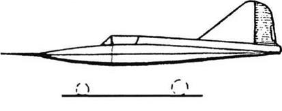
This attractive little machine was rolled out on skis in late 1937 and first flown in 1938. Later in that year it was fitted with a more powerful engine, and with wheel landing gear. Extensive testing, which included sus­tained turns at about 35° bank at different heights, showed that the BICh-20 was stable and controllable, and also could land very slowly.

This aircraft was again a wooden structure, with ply over the leading edge and the vesti­gial fuselage. The wing marked a further change in aerodynamic form: having started with ‘parabola’ designs, Cheranovskii switched to delta (triangular) shapes, and with the BICh-20 adopted a more common form with straight taper, mainly on the lead­ing edge. Trailing-edge controls comprised inboard elevators and outboard ailerons, with prominent operating levers. To enter the cockpit the pilot hinged over to one side the top of the fuselage and integral Plexiglas canopy which formed the leading edge of the fin. The aircraft was completed with Chera – novskii’s ancient British 18hp Blackburne en­gine, in a metal cowling, and with sprung ski landing gear. It was later fitted with wheels, including a tailwheel, and a 20hp French Aubier-Dunne engine.

Подпись: BICh-20 Pionyer (Pioneer). Подпись: BICh-20 All known records suggest that this aircraft was completely successful.

Dimensions

Span

Length, original re-engined Wingarea

6.9m 3.5m 3.56m 9.0 nf

22fl8in Ilft6in 11 ft 8H in 97ft2

Weights

Empty, original

176kg

38815

re-engined

181kg

399 Ib

Loaded, original

280kg

6171b

re-engined

287kg

633 Ib

Performance

Maximum speed, original

160km/h

99 mph

re-engined

166km/h

103 mph

Service ceiling

4,000 m

13,120ft

Range

320km

199 miles

Landing speed

49km/h

30 mph

BICh-18 Muskulyot

BICh-18 Muskulyot

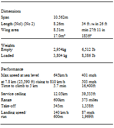
BICh-21.


Dimensions Span Length Wing area

6.75m

4.74m

9.0m2

22 ft K in 15ft63/Un 97.0 ft2

Weights

Empty

526kg

l,1601b

Fuel/oil

37kg

81.6 Ib

Loaded

643kg

l,4181b

Performance

Max speed at sea level,

385 km/h

239 mph

at 4,000m (13,120 ft)

417km/h

259 mph

Landing speed

80 km/h

50 mph


Purpose: To use the tailless concept in a more powerful aircraft for racing.

Design Bureau: B I Cheranovskii.

By the late 1930s Cheranovskii was confident that he could apply his unusual configuration, with no separate horizontal tail, to aircraft in­tended to reach much greater speeds. For the big All-Union race organised by Osoaviakhim to take place in August 1941 he designed a minimalist aircraft broadly like the BICh-20 but with a far more powerful engine. Also designated SG-1, from Samolyot Gonochnyi, aeroplane for racing, it was completed in 1940, but not flown until June 1941. The Ger­
man invasion of 22nd June resulted in the race being cancelled.

With a configuration almost identical to that of the BICh-20, the BICh-21 was likewise all-wood, with polished shpon skin except over the metal engine cowl and cockpit canopy. Unlike the BICh-20 the wing was made as a centre section (with anhedral) and outer panels. This in turn resulted in a differ­ent arrangement of trailing-edge controls, these having reduced chord, with a signifi­cant portion ahead of the trailing edge of the wing, with the elevators divided into two
parts on each side. The engine was an MV-6, the Bessonov licence-built Renault with six aircooled cylinders, rated at 270hp. It drove an imported Ratier two-blade two-pitch (fine or coarse) propeller. A small fuel tank was in­side each side of the centre section. Immedi­ately outboard of these were the landing gears, which retracted backwards under pneumatic pressure.

No records survive of this aircraft’s han­dling or of its fate.

BICh-18 Muskulyot

Подпись: Pi WHmm.BICh-18 MuskulyotПодпись: Dimensions Span 7.5 m 24 ft Tk in It is not known if this is the full-scale Che-22 or a model. Length 5.04m 16 ft 6% in Wing area 14nf 151ft2 Weights Empty 60kg 1321b Подпись: Che-22

Purpose: To investigate a new aerodynamic configuration.

Design Bureau: B I Cheranovskii, by this time working at the MAI (Moscow Aviation Institute).

From 1947 Cheranovskii headed an OKB at the MAI, whose excellent facilities he used in a series of tailless projects. This glider was de­signed in winter 1948-49, and test flown by IA Petrov at Tushino from 17th July 1949.

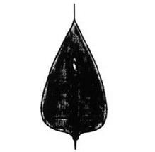
Having progressed from the ‘parabola’ to a form of delta and then to a wing of normal ta­pered shape, this glider comprised a broad flat lifting fuselage, to which were attached conventional wings with modest sweepback. A further innovation was to use more con­ventional trailing-edge controls, mounted on the wing instead of below it. The original Che – 22 drawings show no vertical surfaces what­ever, but later fixed fins were added on the wingtips.

Flight testing appeared to go well, and in late 1949 the DOSAV repair shops tooled up to put the Che-22 into production. Unfortunate­ly, while testing the first to come off the as­sembly line Petrov crashed and was killed, and production was abandoned.

Performance

Not recorded, but ‘aerodynamic efficiency’ (lift/drag ratio) was 18.

BICh-18 Muskulyot

Grushin Sh-Tandem, MAI-3

Подпись: Left: Two views of Sh-Tandem as originally built. Opposite page: Sh-Tandem after modificationGrushin Sh-Tandem, MAI-3

Purpose: To devise an improved configuration for a tactical attack aircraft. Design Bureau: Moscow Aviation Institute, designer Pyotr Grushin.

Born in 1906, Grushin worked on various air­craft at MAI, as well as a remarkable steam engine tested in a U-2 (Po-2). In 1935he began scheming a tandem-wing aircraft, thinking this could form the basis of an attack aircraft with a rear gun turret. The single example of the Sh-Tandem (Shturmovik-Tandem) was constructed in the Institute’s production training school. It was exhaustively tested by P M Stefanovskii from 5th December 1937. Once the dangerously inadequate directional (yaw) stability had been corrected, by adding fins and rudders above the tailplcine, the air­craft flew well. Eventually it was judged to be unreliable and not really needed, but a deriv­ative with armour, an M-82 engine and a can­non in the turret might have proved very useful.

The key feature of this aircraft was that it had a main wing and a rear wing with 45 per cent as much area, both having R-l 1 aerofoil profile. After experimenting with elevens the control surfaces on the rear wing were linked to move in unison as elevators, all lateral con­trol being by the ailerons on the main wing. Fins and rudders were fitted at 50 per cent of the semi-span on the rear wing, initially on the underside only in order to leave a clear 250° arc offire for the electrically driven turret with a ShKAS. Four more ShKAS were to be fixed firing ahead from the main wing, but these cannot be seen in photographs. An in­ternal bay housed a 200kg (441 Ib) bombload. The engine was an M-87 (derived from the

Dimensions Span (main wing) (rear wing) Length

Wing area (total)

11.0m

7.0m

8.5m

30.4m2

36 fl 114 in 23ft

27 ft M in 327 ft2

Weights

Empty

not known

Loaded given variously as

2,560kg

5,644 Ib

and, more likely, as

3,088 kg

6,808 Ib

Performance

Max speed at sea level

406 km/h

252 mph

at 4,200m (13,780 ft)

488 km/h

303 mph

No other data.

Gnome-Rhone K14) radial rated at 930hp. The tailwheel was fixed but the neat main units had single legs and retracted into the wing. The airframe was constructed mainly of wood, with skins of delta bakelite-impreg – nated veneer. Other features included a three-blade variable-pitch propeller, Hucks starter dogs on the propeller shaft, cooling
gills behind the engine cowling, a ventral ducted oil cooler (repeatedly modified) and aft-sliding pilot’s canopy.

Grushin Sh-Tandem, MAI-3

Подпись: Sh-Tandem (upper side view as originally built).
Grushin Sh-Tandem, MAI-3

Despite its extraordinary appearance this aircraft was clearly basically successful. Whether a developed version could have done better than the Ilyushin Shturmovik is problematical.

GUDKOV Gu-1