Category Soviet x-plenes

Yakovlev Experimental Jet Fighters

Yakovlev Experimental Jet FightersYakovlev Experimental Jet Fighters

Purpose: To create fighters and interceptors with new and untried features.

Design Bureau: OKB-115 ofA S Yakovlev, Moscow.

Yakovlev was one of the two General Con­structors who created the first jet aircraft in the Soviet Union (the other was Mikoyan). Yakovlev cheated by, in effect, putting a tur­bojet into a Yak-3 ! A succession of single-en­gined jet fighters followed, one ofwhich was the Yak-25 of 1947 (confusingly, Yakovlev later used the same designation for a different aircraft, see later). This achieved the excel­lent speed of 972km/h (604mph) on the 1,588kg (3,500 Ib) thrust of a single Rolls- Royce Derwent engine (thus, it was faster than a Gloster Meteor on half as many Der­went engines). The first of two Yak-25 proto­types was modified to evaluate an idea proposed by the DA (Dal’nyaya Aviatsiya, long-range aviation). Called Burlaki (barge – hauler) this scheme was to arrange for a strategic bomber to tow a jet fighter on the end of a cable until it was deep in enemy air­space and likely to encounter hostile fighters. The friendly fighter pilot would then start his engine and cast off, ready for combat. The first of the two Yak-25 prototypes was ac­cordingly fitted with a long tube projecting ahead of the nose, with a special connector on the end. The two aircraft would take off in­dependently. The bomber would unreel a cable with a special connector on the end, into which the fighter would thrust its probe, as in probe/drogue flight refuelling. It would thus have a free ride to the target area. The idea was eventually rejected: towing the fighter reduced the range of the bomber, the fighter might not have enough range to get home (unless by chance it could find a friend­ly bomber and hook on), the long tube affect­ed the fighter’s agility and, worst of all, the fighter pilot would have to engage the enemy after several hours sitting in a freezing cockpit with no pressurization.

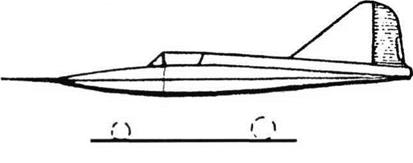
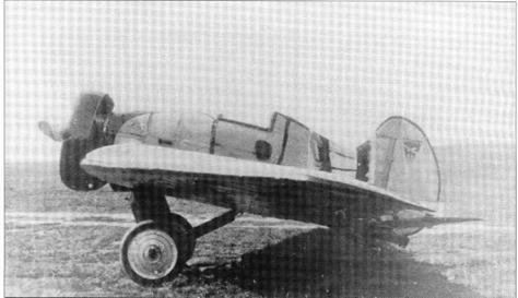
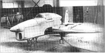
One of the least-known Soviet aircraft was the Yak-1000. The late Jean Alexander was the only Western writer to suggest that this extraordinary creation might have been in­tended purely for research, and even she re­peated the universal belief that its engine was a Lyul’ka AL-5. In fact, instead ofthat impres­sive axial engine of5,000kg (11,023 Ib) thrust, the strangely numbered Yak-1000 had a Rolls- Royce Derwent of less than one-third as muchthrust. Designed in 1948-49, this aircraft was notable for having a wing and horizontal

Centre: Yak-1000.

Bottom: Yak-25E Burlaki.

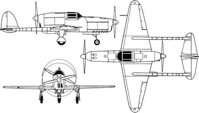
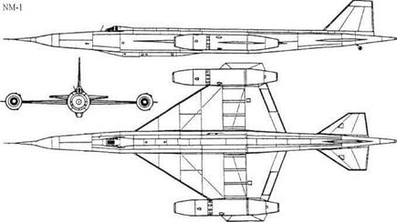
Подпись: Top: Yak-27V. Three views ofYak-28-64 (two R-8T and two R-3S). Yakovlev Experimental Jet Fighterstail of startlingly short span (wing span was a mere 4.52m, 14ft l0in), almost of delta form and with a thickness/chord ratio nowhere greater than 4.5 per cent and only 3.4 per cent at the wing root. Behind the rear spar the en­tire wing comprised a powerful slotted flap, the outer portion ofwhich incorporated a rec­tangular aileron. The tailplane was fixed half­way up the fin, which again was a low – aspect-ratio delta fitted with a small rudder at the top. The long tube-like fuselage had the air inlet in the nose, the air duct being imme­diately bifurcated to pass either side of the cockpit, which was pressurized and had an ejection-seat. The inevitably limited supply of 597 litres (131 Imperial gallons) of fuel was housed in one tank ahead of the engine and another round the jetpipe. The only way to arrange the landing gear was to have a nose – wheel and single (not twin, as commonly thought) mainwheel on the centreline and small stabilizing wheels under the wings. Flight controls were manual, the flaps, land­ing gear and other services were worked pneumatically, and the structure was light alloy except for the central wing spar which was high-tensile SOKhGSNA steel. Only one flight article was built, the objective being a speed in level flight of 1,750km/h (1,087mph, Mach 1.65). Taxi testing began in 1951, and as soon as high speeds were reached the Yak-1000 exhibited such dangerous instabili­ty that no attempt was made to fly it.

In the jet era there is no doubt that Yakovlev’s most important aircraft were the incredibly varied families of tactical twin-jets with basic designations from Yak-25 (the sec­ond time this designation was used) to Yak-28. Some of the sub-variants were exper­imental in nature. One was the Yak-27V, V al­most certainly standing for Vysotnyi, high altitude, because it was specifically intended for high-altitude interceptions. This was a sin­gle flight article, which had originally been constructed as the Yak-121, the prototype for the Yak-27 family, with callsign Red 55. To turn it into the Yak-27V it was converted into a single-seater, and a Dushkin S-155 rocket engine was installed in the rear fuselage, re­placing the braking parachute. The S-155 had a complicated propellant supply and control system, because it combined petrol (gaso­line) fuel with a mixture of RFNA (red fuming nitric acid) and HTP (high-test hydrogen per­oxide) oxidant, plus a nitrogen purging sys­tem to avoid explosions. Brochure thrust of the S-155 was 1,300kg (2,866 Ib) at sea level, rising to 1,550kg (3,417 Ib) at 12km (39,370ft). Airframe modifications included adding an extended and drooped outer leading edge to the wing (though the chordwise extension
was not as large as in the later Yak-28 family), converting the horizontal tail into one-piece stabiliators, fitting the rearranged tankage, and replacing the nose radar by a metal nose. The two NR-30 cannon were retained. The RD-9AK engines were replaced by the spe­cially developed RD-9AKE, with a combustion chamber and fuel system specially tailored for high altitudes; thrust was unchanged at 2,800kg (6,173 lb). Yakovlev hired VGMukhin to join the OKB’s large test-pilot team be­cause he had tested the mixed-power Mikoy – an Ye-50 with a similar S-155 rocket engine. He opened the test-flying programme on 26th April 1956. Service ceiling of the Yak-27V was found to be 23.5km (77,100ft), and level speed above 14km (45,900ft) about 1,913km/h (l,189mph, Machl.8).

Yakovlev had been fortunate in having members of this prolific twin-jet family in se­ries production at four large factories, No 99 at Ulan-Ude, No 125 at Irkutsk, No 153 at Novosi­birsk and No 292 at Saratov. Unfortunately, by 1964 no new orders were being placed and the end was in sight. In that year, right at the end of the development of the family, Yakovlev tried to prolong its life by undertak­ing a major redesign. He sent his son Sergei to study the variable inlets and engine installa­tion of the rival Su-15, and he also carefully studied the MiG Ye-155, the prototypes for the MiG-25. All these were faster than any Yaks, and they had engines in the fuselage. Ac­cordingly, whilst keeping as many parts un­changed as possible, the Yak-28-64 was created, and this single flight article, callsign Red 64, began flight testing in 1966. The en­gines remained the R-l 1AF2-300, as used in most Yak-28s (and also, as the R-l 1F2-300, in many MiG-21s), with dry and afterburning ratings of 3,950kg (8,708 Ib) and 6,120kg (13,492 Ib) respectively. Instead ofbeing hung under the wings they were close together in the rear fuselage, fed by vertical two-dimen­sional inlets with variable profile and area. Drop tanks could be hung under the inlet ducts on the flanks of the broad fuselage. This wide fuselage added almost a metre to the span (from 11.64m, 38ft 2%in, to 12.5m, 41ft), and removing the engines from the wings en­abled the ailerons to be extended inboard to meet the flaps. Armament comprised four guided missiles, two from the K-8 family (typ­ically an R-8M and an R-8T) and two R-3S copies of the American Sidewinder. To Yakovlev’s enormous disappointment, the huge sum spent by the OKB in developing this aircraft was wasted. Its performance was if anything inferior to that of the Yak-28P, and handling was unsatisfactory to the point of being unacceptable.

Top: Yak-36 c/n 38, with rocket pods.

Yakovlev Experimental Jet FightersYakovlev Experimental Jet FightersTwo views of Yak-36 experimental VTOL aircraft.

In 1960 Yakovlev watched the Short SC. l cavorting at Farnborough and became capti­vated by the concept of SWP (Russian for VTOL, vertical take-off and landing). Though he received funding for various impressive Yak-33 studies in which batteries of lift jets would have been installed in a supersonic at­tack aircraft, he quickly decided to build a simple test-bed in the class of the Hawker P.1127, with vectored nozzles. No turbofan existed which could readily be fitted with four nozzles, as in the British aircraft, but, after funding was provided by the MAP and the propulsion institute CIAM, K Khachaturov in the Tumanskii engine bureau developed the R-27 fighter turbojet into the R-27V-300 with a nozzle able to be vectored through a total angle of 100°. Rated initially at 6,350kg (14,0001b), this engine had a diameter of 1,060mm (3ft 5%in) and so it was a practical proposition to fit two close side-by-side in a small fuselage. Of course, the engines had to be handed, because the rotating final nozzle had to be on the outboard side. This was the basis for the Yak-36 research aircraft, intend­ed to explore what could be done to perfect the handling of a jet-lift aeroplane able to hover. To minimise weight, the rest of the air­craft was kept as small as possible. The en­gines were installed in the bottom of the fuselage with nozzles at the centre of gravity, fed directly by nose inlets. The single-seat cockpit, with side-hinged canopy and later fit­ted with a seat which was arranged to eject automatically in any life-threatening situa­tion, was directly above the engines. The small wing, tapered on the leading edge and with -5° anhedral, was fitted with slotted flaps and powered ailerons. Behind the engines the fuselage quickly tapered to a tailcone, and carried a vertical tail swept sharply back to place the swept horizontal tail, mounted
near the top, as far back as possible. The tailplane was fixed, and the elevators and rudder were fully powered. For control at low airspeeds air bled from the engines was blast­ed through downward-pointing reaction-con­trol nozzles on the wingtips and under the tailcone and on the tip of a long tubular boom projecting ahead of the nose. The nose and tail jets had twin inclined nozzles which were controllable individually to give authority in yaw as well as in pitch. The landing gear was a simple four-point arrangement, with wingtip stabilizing wheels, of the kind seen on many earlier Yak aircraft. The OKB factory built a static-test airframe and three flight ar­ticles, Numbered 36, 37 and 38. Tunnel test­ing at C AHI (TsAGI) began in autumn 1962, LII pilot Yu A Garnayev made the first outdoor tethered flight on 9th January 1963 and Valentin Mukhin began free hovering on 27th September 1964. On 7th February 1966 No 38 took off vertically, accelerated to wingborne flight and then made a fast landing with noz­zles at 0°. On 24th March 1966 a complete transition was accomplished, with a VTO fol­lowed by a high-speed pass followed by a VL. The LII stated that maximum speed was about l,000km/h, while the OKB claimed U00km/h (683mph). Both Nos 37 and 38 were flown to Domodedovo for Aviation Day on 9th July 1967. Later brief trials were flown from the helicopter cruiser Moskva.

From the Yak-3 6 were derived the Yak-36M, Yak-38, Yak-38U and Yak-38M, all of which saw service with the A-VMF (Soviet naval avi­ation). This inspired the OKB to produce the obvious next-generation aircraft, with fully su­personic performance. A design contract was received in 1975. Yak called the project Izdeliye (Product) 48, and it received the Ser­vice designation Yak-41. Seldom had there been so many possible aircraft configura-

Yakovlev Experimental Jet Fighters

tions, but at least this time funds were made available for the necessary main engine. With much help from CIAM, this was created as the R-79V-300 by the Soyuz bureau, led after Tu – manskii’s death in 1973 by Oleg N Favorskii, and from 1987 by Vasili K Kobchenko. The R-79 was a two-shaft turbofan with a bypass ratio of 1.0, with a neat augmentor and a fully variable final nozzle joined by three wedge rings which, when rotated, could vector the nozzle through 63° for STO (short take-off) or through 95° for VTO (vertical take-off). Rat­ings were 11,000kg (24,250 Ib) dry, 15,500kg (34,171 Ib) with maximum augmentation and 14,000kg (30,864 Ib) with maximum augmen­tation combined with maximum airbleed for aircraft control. The reason the nozzle vec­tored through 95° was because, immediately behind the cockpit, the Yak-41 had two Ry­binsk (Novikov) RD-41 lift jets in tandem whose mean inclination was 85°. Their noz­zles had limited vectoring but, at this mean position, in hovering flight they blasted down and back so the main engine had to balance the longitudinal component by blasting down and forwards. Sea-level thrust of each RD-41 was 4,100kg (9,040Ib); thus, total jet lift was about22,200kg (48,942 Ib), but in fact the Yak – 41 was not designed to fly at anything like this weight. Compared with its predecessors it was far more sharp-edged and angular. The wing had a thickness/chord ratio of 4.0 per cent, and leading-edge taper of 40°. The outer wings, which in fact had slight sweepback on the trailing edge, folded for stowage on air­craft carriers. The leading edge had a large curved root extension, outboard of which was a powerful droop flap. On the trailing edge were plain flaps and powered ailerons. The wing had -4° anhedral, and was mount­ed on top of a wide box-like mid-fuselage, from which projected a slim nose and cock-

pit ahead of the large variable wedge inlets which led to ducts which, behind the lift engines, curved together to feed the main en­gine. The latter’s nozzle was as far forward as possible. Beside it on each side was a narrow but deep beam carrying a powered tailplane and a slightly outward-sloping fin with a small rudder. Unlike most military Yak jets the Yak-41 had a conventional tricycle landing gear. In hovering flight recirculation was min­imised by the open lift-bay doors, a hinged transverse dam across the fuselage ahead of the main gears, a large almost square door hydraulically forced down ahead of the main engine nozzle, and a long horizontal strake along the sharp bottom edge of the fuselage on each side. Fuselage tanks held 5,500 litres (1,210 Imperial gallons) of fuel, and a 2,000 litre (440 Imperial gallon) conformal tank could be scabbed under the fuselage. Flight and engine controls were eventually inter­linked and digital, the hovering controls com­prising twin tandem jets at the wingtips and a laterally swivelling nozzle under the nose (which replaced yaw valves at the tip of each tailcone). An interlinked system provided automatic firing of the K-36LV seat in any dan­gerous flight situation. In 1985 it was recog­nized that such a complex and costly aircraft ought to have multi-role capability, and the new designation Yak-41 M was issued for an aircraft with extremely comprehensive avion­ics and weapons. Equipment included a 30mm gun and up to 2.6 tonnes (5,732 Ib) of ordnance on four underwing pylons. The OKB received funding for a static/fatigue test aircraft called 48-0, a powerplant test-bed (48-1) and two flight articles, 48-2 (callsign 75) and 48-3 (callsign 77). Andrei A Sinitsyn flew ’75’ as a conventional aircraft at Zhu – kovskii on 9th March 1987. He first hovered ’77’ on 29th December 1989, and in this air­craft he made the first complete transition on 13th June 1990. Maximum speed was 1,850km/h (1,150mph, Mach 1.74) and rate of climb 15km (49,213ft) per minute. In April 1991 Sinitsyn set 12 FAI class records for rapid climb with various loads, and as the true des­ignation was classified the FAI were told the aircraft was the ‘Yak-141’. In September 1992 48-2 was flown to the Farnborough airshow, its side number 75 being replaced by ‘141’. A year earlier the CIS Navy had terminated the whole Yak-41 M programme, and the appear­ance in the West was a fruitless last attempt to find a partner to continue the world’s only programme at that time for a supersonic jet – lift aircraft. Apart from publicity, all today’s Yakovlev Corporation finally received for all this work was a limited contract to assist Lockheed Martin’s Joint Strike Fighter.

Opposite: Yak-41 M with Yak-38M.

Подпись:Подпись:Подпись:Подпись:Yakovlev Experimental Jet FightersПодпись:Yakovlev Experimental Jet FightersПодпись: Yak-141 inboard profileYakovlev Experimental Jet FightersThis page, top: Yak-141, No 75 on carrier.

BICh-14

Purpose: To test an improved twin-engined ‘Parabola’.

Design Bureau: B I Cheranovskii.

In 1933 Cheranovskii schemed his first design with twin engines, the BICh-10. Later in that year he tested a tunnel model, and by 1934 he had made so many (mostly minor) changes that he redesignated it as the BICh-14. It in­terested the Central Construction Bureau, and thus received their designation CCB-10 (TsKB-10). With their assistance the aircraft was built, and the flight-test programme was opened at the end of 1934 by Yuri I Piont – kovskii. Having no slipstream, the rudder was ineffective, and it was difficult to equalise pro­
peller thrusts. On landing, with engines idling, a heavy stick force was needed to get the tail down. Though it was not one of the better BICh designs, having almost no directional stability and being extremely reluctant to re­spond to pilot inputs, it was submitted for NIl – WS testing. Here such famous pilots as Stefanovskii, Petrov and Nyukhtikov flew it, or attempted to. Various changes made this air­craft marginally acceptable, but attempts to improve it ceased in 1937 Again this was a wooden aircraft, with a skin of veneer (over the leading edge) and fabric. An innovation was to use aluminium to make the embryonic fuselage, which seat­ed up to five, and the integral fin. The wing
had four spars and 60 ribs, and was made as a centre section, of 3.3m (10ft l0in) span, and bolted outer panels. Close together on the leading edge were the two l00hp M-ll en­gines, with Townend-ring cowls, aluminium nacelles and U-2 type wooden propellers. As before, virtually all the development effort went into improving the trailing-edge con­trols, of which there were three on each wing, all hung in the usual Junkers style below the trailing edge. For most of the time the four inner surfaces were elevators and the outers ailerons, but at times the middle surfaces were tested as flaps.

The BICh-14 apparently did nothing to en­hance its designer’s reputation.

Dimensions Span Length Wing area

16.2m

6.0m

60m2

53 ft 2 in 19 ft 9 in 646ft2

Weights

Empty

1,285kg

2,833 Ib

Loaded

1,900kg

4,1891b

Performance

Maximum speed, approx

220km/h

137 mph

Range

370km

230 miles

Landing speed

70km/h

43.5 mph


BICh-14.


BICh-14BICh-14

Purpose: To attempt to fly on human muscle power.

Design Bureau: B I Cheranovskii.

Ever one to explore fresh ideas, in 1934 Cher­anovskii obtained financial support from Osoaviakhim (the Society of Friends of the Aviation and Chemical industries) for his pro­
posal to build a man-powered ornithopter (flapping-wing aircraft). It could not be made to fly.

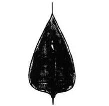
This bird-like machine consisted mainly of a flexible wing. The pilot placed his feet on a rudder bar directly under the rudder and then bent forward between two vestigial fins until he could grasp the spade-grip which, via the
two struts seen in the photo, flapped the wings. The two struts and vertical operating rod were pivoted at the bottom to a curved landing skid.

Data not recorded.

Two views of BICh-16.

BICh-14


Grokhovskii G -31, Y akob Alksnis, Strekoza

Purpose: To build a troop-carrying glider; this was later modified into powered aircraft.

Design Bureau: WS-RKKA (Red Army special design team for aviation forces), director Pavel Ignatyevich Grokhovskii (1899-1946).

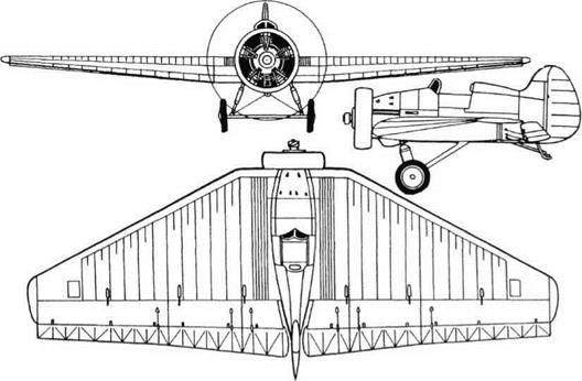
Grokhovskii had a brief but intense career, forming a branch of WS-RKKA in Leningrad in 1934 and seeing it liquidated in 1936. Most of his designs were concerned with as­sault by airborne forces, and all showed a re­markable originality. The G-61 was a ‘people pod’ able to house seven armed troops and actually flown attached under each wing of an R-5, a mass-produced 700hp biplane. The G-31 (in some documents called G-63i>/s), named for WS Gen Yakob Alksnis, was a giant cargo glider, designed by Grokhovskii and B D Urlapov to carry troops lying inside the wing. From this Grokhovskii produced the G-31 powered aircraft. First flown in late 1935, it flew to Moscow in 1936 for RKKA test­ing. It was eventually decided that the
arrangement of troops packed inside the wing, with no chance of escape in flight, was unacceptable. In any case, the concept of a powered glider for assault operations was eventually considered unsound.

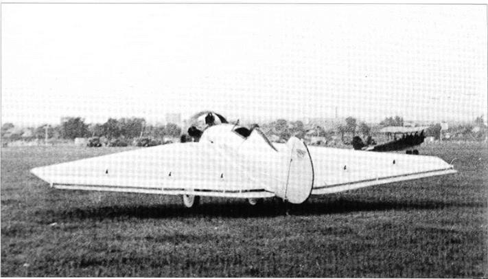
Sharing a strengthened version of almost the same airframe as the glider, the G-31 (again named for Alksnis and also dubbed Strekoza, dragonfly) was a graceful aircraft as befits a powered version of a glider. Though intended for military purposes it was one of several types designed in the 1930s with no consideration of speed, because this was not thought significant. The airframe was wooden, with a vestigial fuselage of multiply veneer formed by presses with double curva­ture. On the front was a puny 100hp M-l 1 five – cylinder radial. Subsequently Grokhovskii built a G-31 with a strengthened structure matched to the 700hp M-25, an imported (later licensed) Wright R-1820 Cyclone. This was fitted in a Townend-ring cowl and it drove a Hamilton light-alloy ground-ad­justable propeller. It is believed that later a three-blade flight-variable Hamilton Standard
was fitted. As in the glider there were cockpits for a pilot and flight engineer, while between the wing ribs were compartments for 18 troops, nine in each wing (drawings show eight in each wing). They boarded and were extracted through hinged leading edges, which were transparent, as in the G-61 pods.

Few details of the G-31 have survived. Clearly the naming of this aircraft and its predecessor after Alksnis was a mistake, because he was arrested in 1936 and execut­ed in 1938. The close-knit Grokhovskii team was ‘liquidated’ very soon after the General’s arrest.

Grokhovskii G -31, Y akob Alksnis, Strekoza

Dimensions (M-25 engine)

Span

Length

Wing area

28.0m

13.9m

70.5m2

91 ft M in 45 ft 7n in 759 11!

Weights

Empty

1,400kg

3,086 Ib

Loaded

3,200kg

7,055 Ib

Performance Maximum and cruising speed limited to

135km/h

84 mph

No other data.


Left: G-31 with M-25 engine.

Below left: G-31 glider.


Below right: G-31 with M-l 1 engine.

Grokhovskii G -31, Y akob Alksnis, Strekoza


Grokhovskii G -31, Y akob Alksnis, Strekoza

Grokhovskii G -31, Y akob Alksnis, Strekoza

Lavochkin La 7R and f120Rf

Purpose: To use a rocket engine to boost a fighter’s flight performance.

Design Bureau: OKB of Semyon A Lavochkin.

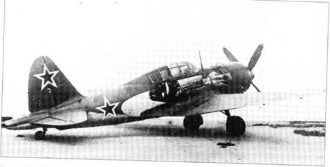
By early 1944 the all-wood La-5 fighter had given way in production to the La-7, with metal spars and other modifications. The en­gine remained the ASh-82FN 14-cylinder radi­al rated at 1,600hp. One ofthe first production aircraft was fitted with an RD-1 rocket engine in order to boost its performance, especially at extreme altitudes where the ASh-82 family of engines were less impressive. The installa­tion was completed in the late autumn of 1944, and ground testing occupied nine weeks. In the last week of the year the as­signed pilot, Georgii M Shiyanov, began the flight-test programme. Together with AVDavydov the La-7R was flown 15 times without serious malfunction, though the pro-

Lavochkin La 7R and f120Rf

Above: Ground test of ‘120R’ rocket engine. Opposite: Two views of La-7R.

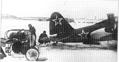
gramme had to be abandoned because of progressive weakening of the rear fuselage by vapour and accidental spillage of the acid. Testing was continued with the RD-lKhZ in­stalled in a second La-7R in early 1945. Brief testing was also carried out with a similar en­gine installed in the ‘120R’. On 18th August 1946 this aircraft excited spectators at the Avi­ation Day at Tushino by making a low flypast with the rocket in operation.

Both the La-7R test aircraft were originally standard production fighters. The RD-1 was one of the world’s first liquid-propellant rock­et engines to fly in a manned aircraft, the de­signer being V P Glushko. The thrust chamber was mounted on a framework of welded steel tubes carried behind a modified rear fuselage frame, which merged at the top into the fin trailing edge. To accommodate the rocket the lower part of the rudder was re­moved. In the fuselage behind the cockpit were a stainless-steel tank for 180 litres (39.6 Imperial gallons) of RFNA (concentrated red fuming nitric acid) and 90 litres (19.8 Imperi­al gallons) of kerosene. These propellants were supplied by a turbopump energised by hot gas bled from the main thrust chamber. The turbine had a governed speed of 26,000rpm, and drove pumps for the two pro­pellants plus lubricating oil and water sup­plied from a small tank to cool the turbine and thrust chamber walls. Mass of the installation was approximately 100kg (220 Ib), or 215kg (474 Ib) complete with propellants and water. The basic RD-1 had electrical ignition, while the RD-1KhZ had automatic chemical ignition from hypergolic liquids. The rocket was ofthe on/off type, cut in or out by a switch on the main throttle lever. It could not be varied in thrust (300kg, 661 Ib, at sea level), but could be shut off before the tanks were empty, nor­
mal duration being 3 to 31/2min. Both La-7R air­craft retained their armament of two UB-20 cannon. The ’ 120R’ differed in having an ASh – 83 engine, rated at 1,900hp, armament of two NS-23 guns and in other details.

Together with such other aircraft as the Pe – 2RD and Yak-3RD these test-beds confirmed the value of a rocket engine in boosting per­formance at high altitude. On the other hand they also confirmed that RFNA is not compat­ible with a wooden structure, and in any case the value of three minutes of boost was con­sidered questionable.

Dimensions (both)

Span

Length

Wing area

9.8m

8.6m

17.59m2

32 ft IK in 28 ft TM 189ft2

Weights (La-7R)

Empty

2,703kg.

5,959 Ib

Fuel and propellants

604kg

l,3321b

Loaded

3,500kg

7,716 Ib

Weights (‘120R’)

Empty

2,770kg

6,107 Ib

Fuel and propellants

470kg

l,0361b

Loaded

3,470kg

7,650 Ib

A standard La-7 typically had empty and loaded weights of 2,600kg and 3,260 kg

Performance

(La-7R) generally unchanged, but maximum speed at 6 km (19,685 ft) altitude was increased from 680 km/h (422.5 mph) to 752 km/h (467 mph).

Service ceiling was increased from 10,700 m (35,105 ft) to 13,000 m (42,651 ft).

The only figure recorded for the ‘120R’ is a speed (height unstated) of 725 km/h (450.5 mph), but this speed (at 7,400 m) is also recorded for the unboosted ‘120’.

Lavochkin La 7R and f120Rf

Lavochkin La 7R and f120RfLavochkin La 7R and f120Rf

Ye-6T/l (Ye-66A)

In 1960 the Ye-6T/l, the first true series-built MiG-21, callsign Red-31, was rebuilt for record purposes, with various modifications. In order not to reveal too much to the FAI in­ternational body, it was given the invented designation Ye-66A. The most obvious change was to attach a rocket package un­derneath the fuselage. The rocket engine was designated S-3/20M5A, the ultimate version of Dushkin’s family burning kerosene and RFNA fed by peroxide turbopumps. The propellants were packaged with the engine and control system in a large gondola designated U-21. Thrust was 3,000kg (6,614 Ib) at sea level, ris­ing to about 3,700kg (8,150 Ib) at high altitude. The rocket nozzle was angled 8° downwards, but despite this it was necessary to replace the usual MiG-21 underfin by two shorter but deeper ventral fins each inclined outwards. The main engine was replaced by an R-l 1F2- 300, with a maximum afterburning rating of 6,120kg (13,492 Ib); this engine later became standard on the MiG-21 PF. Other modifica­tions included 170 litres (37.4 Imperial gal­lons) of extra kerosene fuel in a spine fairing behind the canopy, and a fin extended for­wards to increase area of the vertical tail to 4.44m2 (47.7ft2). The Ye-66A did not set any ratified speed records, but on 28th April 1961 it was flown by G K Mosolov in a zoom to a new world absolute height record of 34,714m (113,891ft). He made a low flypast with rock­et in operation at the airshow at Moscow Tushino on Aviation Day (9th July) 1961.

Petlyakov Pe-2 experimental versions

Purpose: To test various items on modified Pe-2 aircraft.

Design Bureau: Basic aircraft, ‘100’ in special prison CCB-29 (TsKB-29), later V M Petlyakov’s own OKB.

Production of this outstanding fast tactical bomber totalled 11,427. One of the experi­mental wartime versions was the Pe-2Sh (Shturmovik, assaulter) with various combi­nations of20mm ShVAK cannon and 7.62mm ShKAS either firing ahead from a gondola or installed in one or more batteries firing obliquely down from what had been the fuse­lage bomb bay. The Pe-2VI and Pe-2VB were
special high-altitude versions with pressur­ized cabins and VK-105PD engines with two – stage superchargers. The Pe-2RD was fitted with a Dushkin/Glushko RD-1 or RD-lKhZ rocket engine installed in the tailcone, with the tanks and control system in the rear fuse­lage. This aircraft was tested in 1943 by Mark L Gallai. Like the similarly modified Tu-2, the Pe-2 Paravan (paravane) had a 5m (16ft Sin) beam projecting ahead of the nose from the tip of which strong cables led tightly back to the wingtips. While the Tu-2 had a tubular beam, that of the Pe-2 was a truss girder, and the balloon cables struck by the wires were deflected further by large wingtip rails. From
1945 one Pe-2, as well as at least one Tu-2, was used by CIAM and Factory No 51 to flight test a succession of pulsejet engines begin­ning with captured German Argus 109-014 flying-bomb units. Test engines were mount­ed above the rear fuselage, with fuel fed by pressurizing the special aircraft tank to 1.5kg/cm2 (21.31b/in2). In 1946-51, under V N Chelomey, Factory 51 improved this Ger­man pulsejet into a succession of engines designated from D-3 to D-14-4. All the early models were tested on the Pe-2, despite fatigue caused by the severe vibration.

Petlyakov Pe-2 experimental versions

Petlyakov Pe-2 experimental versions

Rear defence by aft-firing RO-82 rockets: RUB-2L dorsal and RUB-4 ventral.


Petlyakov Pe-2 experimental versionsTop left: Twin ShVAK-20 cannon in Pe-2Sh (two more were further back).

Подпись:
Right: Pe-2VI.

. Sukhoi 100LDU

Purpose: To flight-test canard surfaces. Design Bureau: P O Sukhoi, Moscow

As explained in the history of the T-4, this enormous project required back-up research right across Soviet industry. The Sukhoi OKB
itself took on the task of investigating the proposed canard surfaces. As the only vehicle immediately available was a two-seat Su-7U, with a maximum Mach number of 2 instead of 3, the resulting aircraft – with designation 100LDU – ceased to be directly relevant to the

T-4 and became instead a general canard research vehicle. It was assigned to LIl-MAP test pilot (and future Cosmonaut) Igor Volk, and was tested in 1968-71.

The basic Su-7U, powered by an AL-7FI – 200 with a maximum afterburning rating of 10,100kg (22,282 Ib), was subjected to minor modifications to the rudder and braking- parachute installation, and was fitted with fully powered canard surfaces on each side of the nose. These were of cropped delta shape, with a greater span and area than those of contemporary experimental MiG aircraft, and with anti-flutter rods which were longer and nearer to the tips.

This aircraft fulfilled all test objectives, though the numerical data were of only marginal assistance to the T-4/100 design team.

SLIKHOI 02-10, OR L02-10

. Sukhoi 100LDU

Purpose: To investigate direct side-force control.

Design Bureau: P O Sukhoi, Moscow.

In 1969 this Su-9 was modified for the LII, which wished to investigate the application of direct side force. The LII had been concerned at American research into direct lateral or ver­tical force which could enable a fighter to rise, fall, move left or move right without changing the aircraft’s attitude. In other words such an aircraft could keep pointing at a target in front while it crabbed sideways (for example). Testing began in 1972. In 1977 the aircraft was returned to a Sukhoi OKB factory and had the upper nose fin removed, testing continuing as a joint LII/Su programme. It was further modified in 1979.

Originally this aircraft was a production Su – 9 interceptor, though it never saw active ser­vice. In its first 02-10 form is had substantial vertical fins added above and below the nose. Each fin was pivoted at mid-chord and fully
powered. The pilot was able to cut the nose fins out of his flight-control circuit, leaving them fixed at zero incidence. When they were activated, movement of his pedals drove the fins in unison with each other and in unison with the rudder. The two canard fins moved parallel to the rudder, to cause the aircraft to crab sideways. Each surface was of cropped delta shape, with a lower aspect ratio than the horizontal canards of the S-22PDS. Compared with the lower fin the upper surface had significantly greater height, and it was mounted slightly further forward. Each was fitted with an anti-flutter rod mass,
which during the course of the programme was moved from 40 per cent offin height (dis­tance from root to tip) to 70 per cent. After the 02-10’s first series of tests the upper nose fin was removed (leaving its mounting spigot still in place). Later a cine camera was installed on the fin to record lateral tracking across the ground, and in some of the later tests the wings were fitted with smoke nozzles along the leading edge, to produce visible stream­lines photographed by a camera in a box im­mediately ahead of the radio antenna.

This aircraft generated useful information, but the idea has never been put into practice.

Three different versions of L02-10 test-bed.

. Sukhoi 100LDU


Type 346

Type 346Подпись: 346A carried by B-29, front and plan views of any version except 346-3.Подпись: 346A (346D similar)Type 346Подпись: Inboard profile of 346-3Type 346

Purpose: To continue German development of a supersonic rocket aircraft.

Design Bureau: OKB-2 at Podberez’ye, lead designer Hans Rosing, in October 1948 replaced by S M Alekseyev.

On 22nd October 1946 a second group of German design engineers was formed at Pod – berez’ye to continue development of the DFS – 346 supersonic research aircraft originally designed at the DPS (German institute for glid­ing) at Griesheim near Darmstadt. Models, some made in Germany, were tested in CAHI (TsAGI) tunnels, and a North American B-25 was fitted with a mock-up nose to test the cockpit jettison system. In 1947 (date not dis­covered) the 346P (P from planer, glider) un­powered version was taken to the test airfield at Tyoplyi Stan and dropped from under the starboard wing of a captured B-29 (previously USAAF 42-6256). Amazingly, the 346P was flown not by a Russian but by Wolfgang Ziese, who had previously been chief test pilot of the Ger­man Siebel Flugzeugwerke. He had no prob­lems, and brought the glider to a normal landing. In 1948 (date not discovered) the 346­1 high-speed glider version, also known as the 346A, was released from a Tu-4 (B-29 copy) and similarly flown by Ziese to a normal landing. On 30th September 1949 the 346-2, also known as the 346D, was dropped from the B-29 and flown as a glider by Ziese even though it was fitted with rocket propulsion. No propellant was loaded, so the aircraft was much lighter than it would have been with full tanks. Despite this Ziese landed too fast and, more seriously, the landing skid failed to extend, resulting in seri­ous damage to both the aircraft and pilot. This aircraft was repaired, and in October 1950 LII pilot P I Kasmin flew it at Lukhovitsy, according to the record making a normal take-off from the runway despite having only skid landing gear. Ziese recovered, and on 13th August 1951 he flew the final aircraft of this programme, the 346-3, and fired the engines. He flew again on 2nd September, but on the third flight, on 14th September, he lost control. He managed to sep­arate the jettisonable nose from the tumbling aircraft, but this ended the programme. Later versions were abandoned. Various 346 parts were donated to the Moscow Aviation Institute.

Like its American counterpart the Bell XS-1, the 346 was an almost perfectly streamlined body with mid-mounted wings. Unlike the XS – 1, it had a prone pilot position, skid landing gear, swept wings and an extremely squat ver­tical tail with the tailplane on top. Construction was almost wholly flush-riveted light alloy. The wings had NACA-012 profile (12 per cent thick) and a sweep angle of 45° at the /4-chord line. Each wing had two shallow fences from the

Подпись: Opposite page, top: B-25 with 346 cockpit capsule. Подпись:Подпись: Above: 346-2 (346D) nose open showing pilot couch. Right: Looking down into open nose. Below: Three views of 346-2 on B-29. Type 346Подпись: Performance Max speed, intended 2,127 km/h 1,322 mph (Mach 2) in a 2 min full-power burn at high altitude No other data. Type 346leading edge to the plain flap. At the tips were inverse-tapered two-section ailerons, the inner sections being locked at high airspeeds. The elevators were similar in principle. On the 346P the tailplane, with!4-chord sweep of 35°, was fixed and surmounted by a small fixed fin. On the 346-2 and -3 the tailplane was driven by an irreversible power unit over the range -2° 407+2°. The fuselage was of circular sec­tion, with the entire nose arranged to slide forward for pilot entry and to jettison in emer­gency. The pilot lay on his stomach looking ahead through the Plexiglas nosecap, through which protruded the long instrumentation boom. Bottled gas pressure operated the flaps and retracted the skid into a ventral recess which, except for the 346P, could be faired over with twin doors. Under the tail was a small steel bumper. Unlike its predecessors, the 346-3 could be fitted with a curved skid with a levered shock strut hinged under each outer wing. These were jettisoned after take-off. The propulsion system was the Walter HWK 109- 509C, called ZhRD-109-510 in the USSR. This had two superimposed thrust chambers, one which fired continuously whenever the system was in operation, and a larger chamber used only for take-off or for brief periods when max­imum thrust was needed. The cruise chamber was rated at sea level at 300kg (661 Ib), and the main chamber at 1,700kg (3,7481b). The com­bined thrust at high altitude was about 2,250kg (4,960 Ib). Immediately behind the jettisonable nose section was a tank of concentrated hyd­rogen peroxide (called T-Stoff in Germany) while in the centre fuselage were intercon­nected tanks of methanol/hydrazine hydrate (C-Stoff). German turbopumps running on cal­cium permanganate fed the highly reactive flu­ids to the thrust chambers, where ignition was hypergolic (instantaneous).

Probably as much effort went into the 346 programme as the Americans expended on the XS-1 or D-558-II, but there was no comparison in what the programmes achieved. There is no obvious reason why these challenging aircraft, designed for Mach 2, should simply have been abandoned without even reaching Mach 1.

Dimensions

Span 9 m 29 ft 6% in

Length

(346-3, nose to engine nozzles) 13.447 m 44 ft IK in (instrument boom to tailplanes) 15.987 m 52 ft 3SA in Wing area (net) 14.87nf 160ft2

Weights (346-3)

Empty 3,180kg 7,01 lib

Propellants 1,900kg 4,1891b

Loaded 5,230kg ll,5301b