Category And Colors

DESIGN REQUIREMENTS

D-l. Markings for Large Seaplanes and Amphibians.

D-la. Wing Tips.-

D-la(l). Wing tip floats and struts shall be painted orange-yellow.

D-la(2). Upper and lower surfaces of both wing tips shall be painted orange-yellow from the wing tip inboard a distance equal to 7 percent of the total wing span (float excluded). A black border 6 inches in width shall be added inboard.

D-lb. Wing, Center Section (Upper Surface Only).

D-lb(l). The upper surface of the center section, including the rear projection portion of the engine nacelles, shall be painted orange-yellow to a distance just outboard of the two inboard engine nacelles, A black border 6 inches in width shall be added outboard.

image438

Lockheed P-80A-1-LO, 44-85004, was the thirteenth one built and was significant as being the first jet fighter to enter service with the AAF. The initial jet fighters for the AAF were puttied all over and finished with a very smooth ANA 602 light gray finish to improve performance. However, this finish quickly became chipped and scarred in service and was soon discarded. (March AFB Museum)

D-lb(2). On the upper surface, the word “RESCUE” shall be superimposed in black. Centered aft of the word “RESCUE”, the appropriate identification numerals and/or letters shall be added. Letters and numerals shall be of the modified vertical block type, uniform in shape and size, and shall be 36 inches high, 27 inches wide, and the width of the individual strokes forming them shall be 6 inches. The spacing between letters shall be 12 inches.

D-lc. Hull.-

D-lc(l). Hull (Rear Section).- A 36-inch orange-yellow band, approximately three feet forward of the leading edge of the hori­zontal stabilizer, shall encircle the aft portion of the hull, but not extend onto the last step or keel. Two 6-inch black stripes shall be added as borders.

D-lc(2). Hull (Forward Section).- On each side of the forward part of the hull and centered between the leading edge of the wing and the bow, an orange-yellow rectangle, whose length shall be equal to three times its height, shall be painted. Atwo-inch black stripe shall border the rectangle. The height of the rectangle shall be 33 percent of the vertical dimension of the projection of the fuselage side at the point of application, except that the height of this rectangle shall be not greater than 36 nor less than 20 inches excluding the border. The rectangle shall be located as near as possible to the center of the vertical projection of the fuselage at the point of application. The national aircraft insignia, which normally would occupy this space, shall be located aft on the hull to clear this marking.

D-lc(2)a. Identification Numbers.- The Air-Sea-Rescue identification numbers and/or letters shall be of the modified vertical block type, uniform in shape and size, and shall be approximately 2/3 of the height of the orange-yellow rectangle. The width of the letters and numerals shall be 3/4 of the height and the width of the individual strokes forming them shall be 1/6 of the height. The letters’and numerals shall be appropriately spaced.

D-lc(3). Hull (Bottom Section).- On the bottom of the hull, between the bow and the main step, and extending from chine to chine, the Air-Sea-Rcscue identification numerals and/or letters shall be painted. The top of the letters and/or numerals shall be at the port chine of the hull. Letters and numerals shall be orange-yellow, bordered by a two-inch black stripe. The width of the letters and numerals shall be 3/4 of the height, and the width of the individual strokes forming them shall be 1/6 of the height. The letters and numerals shall be appropriately spaced.

D-2. Markings for Other Aircraft.- The markings, as specified above, shall be used as appropriate to the size and shape of the aircraft.

Lockheed P-80A-1-LO, 44-85168, 44-85154, 44-85167, 44-85093, 44-85089, and 44-85160 of the 1st FG, being serviced on the ramp at March Field, California, in the summer ofl 946. Two others are flying overhead. The first unit to be equipped with the P-80, it moved to George AFB in July, 1950. (March AFB Museum)

image439

image440

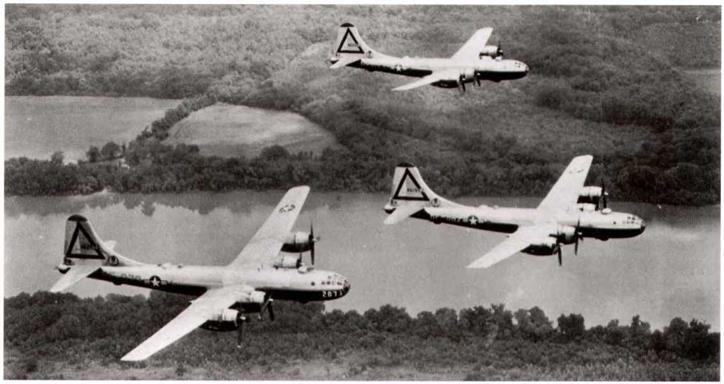
Boeing B-29-55-MO, aircraft 6383 of the famous 509th Composite Group, attached to the 3I3th Wing, Twentieth Air Force, in June 1945. It has black and red bands around the rear fuselage. This aircraft is marked with the group’s arrowhead marking. It is finished in Jet 622 Gloss Black on all lower surfaces. Note the atomic explosion insignia on fuselage. Seen after August, 1945. (USAF via Gerry R. Markgraf)

White and Haze Paints tested on Pursuit Aircraft, January 1942

Exp. Eng. Sect. (WF), investigated the method for camouflaging pursuit aircraft which were being used in studies of photographic installations. Two kinds of paint were used for the tests, namely:

(1) Cabot Haze Paint, which was a colloidal dispersion of zinc oxide in oil. The plane had a bluish appearance (sky) when the paint was applied in a thin coating over a black background.

(2) A pinkish white and a micaceous paint procured from the Lowe Bros. Paint Co, Dayton, Ohio (hereafter Lowe Bros.) The tentative conclusions were that a flat white camouflage paint was most suitable for camouflage against clouds and the haze paint was preferable for blue-sky conditions. Exp. Eng. Sect, stated that further tests would be conducted to ascertain satisfactory results.

image90

North American B-2SA-NA, one of forty buiit before production shifted to the improved B-25B-NA version. The beam and ventral gun posi­tions of the B-25A were replaced on the B-25B by dorsal and ventral gun turrets with two 0.5 inch guns each. (March AFB Museum)

Permanent Camouflage Paints tested in Florida, January 1942.

Suitable finishes for permanent camouflage of aircraft were discussed in a report prepared by WF. Laboratory tests of applications and removal, adhesion, durability and optical reflection characteristics were included in the investigation. WF concluded that, after five months of Florida exposure, permanent materials, of low gloss, color retention and satisfactory adhesion, had been developed, A method of measuring the specular gloss of camouflage finishes had also been developed.

image91

Six of the sixteen B-25B-NAs on (he deck of the USS Hornet, Only visible radio call number is 40-2283. (USAF)

image92Two of the B-25B-NA* of Col. Jimmy Doolittle’s Tokyo strike force on the deck of the carrier CSS Hornet, on April 18,1942. The right aircraft is 40-2282. Note how crammed the aircraft were on the deck. (USAF)

Nose art on one of the Doolittle B-25B-NAS, appears to be painted in vvhitc. This attack achieved little in damage to Japan, but it came as a tremendous morale booster at a sorely needed time, and showed the Japanese that they were also now susceptible to attack by LIS forces. (1ISAF)


image93

image94

Douglas B-18B-DO, 37-530, in Theater 5, the Caribbean and British West Indies area. It is fitted with a very early MAD {Magnetic Anomaly Detection) boom, which appears to have its cover installed upside down. Although it has the post May 1942 cocarde without the red center circle, it is still in dark olive drab and neutral gray finish, despite the drive for a white anti-submarine aircraft finish. (USAF)

Request by the RAF for standardization of B-I7E camouflage, January 28,1942.

The RAF requested that the JAC make another effort to standardize the camouflage being applied to B-17Es at the modification centers, commenting that the previous differences of location of operational units of the two countries did not now apply, so it should be possible to find a common camouflage scheme for each class of aircraft. Under the aircraft allocation pooling then in force, it was difficult to paint different patterns at the manufacturing plants.

Technical Sub-Committee On Camouflage decides that the AAF basic camouflage scheme and the U. S. Navy basic camouflage scheme be accepted as the production standard for all aircraft produced in the U. S. March 5, 1942.

The Technical Sub-Committee on Camouflage met on March 5, 1942, to discuss the problems raised by the British Air Committee requiring that British camouflage schemes be painted at the factory on all aircraft destined for the RAF and FAA. This was to be applied

image95

A Curtiss P-40E, ‘585’, being towed in Alaska. It has the famous Aleutian Tiger markings, plus white stripes on the fuselage and rudder. Note the blue and gray PBY in the background. (USAF)

image96

Convair B-24E-DTs on the new production line at the Douglas Tulsa plant in 1942. Ten B-24Ds and 167 B-24Es were built on this line before shifting to the later B-24H version. This photo is a graphic reminder of the enormous production capacity of the US aircraft industry, built up by joint planning between the ЛАТ and civilian industry. More B-24s were built than any other US aircraft in World War 11, but it was taken out of service almost overnight at the end of the war. (Harry Gann)

either before the aircraft left the U. S. or after it reached the British theater of war. The British also stated that it was impossible for them to accept the U. S. camouflage schemes operationally.

The Sub-Committee decided that it was impracticable to adopt the British schemes as standard, because that system was based on the Service being able to anticipate the aircraft’s operational theater or role while it was being completed at the manufacturer.

They then considered camouflage schemes which could be used as a basis for all aircraft and could be converted to other services requirements with the least difficulty. It was agreed that this consideration could be converted into two standard basic schemes, (1) camouflage for land based aircraft, (2) camouflage for ship based aircraft, this to also include flying boats.

The British representative stated that 70% of the British camouflage schemes used a “Dark Green,” which was very similar to the Army dark olive drab, thus they could accept this in lieu of the Dark Green throughout the camouflage programs. For ship based aircraft, the British stated that the U. S, Navy colors would be acceptable.

The current policy of pooling all aircraft production was given as a very strong reason to accept the two basic camouflage schemes, and this was accepted by all present. It was also recommended that the requirements for insignia and markings of a particular Service be accomplished as follows:

a. When the allocation of aircraft was determined before production was complete, the insignia and markings of a particular Service would be applied at the factory.

b. When an aircraft was diverted from one service to another, the change of insignia and markings would be made at the modification centers.

In conclusion, the British representatives at the meeting agreed to submit the U. S. Navy camouflage system to the authorities in Great Britain for a decision as to whether or not it was acceptable. It was also agreed that the British would submit to the U. S. Army their specific requirements for camouflage on all types of Army aircraft in production in the US.

image97

One North American B-25C-NA, 41-12848, with two B-25Ds, operating in the anti-submarine role. B-2SD-1-NC, 41-29917, has no ventral turret, while B-25D-20-NC, 41-30583 has both ventral and dorsal turrets. The latter aircraft were the Kansas city built version of the B-25C. Note the white anti-submarine finish on the B-25C. (Harry Gann)

Responsibility for Aircraft Camouflage development defined, April 1942,

At this time, the Chief of Engineers was the War Dept. Agency responsible for the development of protective coloration and camouflage of all items of equipment, supplies and materials except aircraft. The Air Corps Board had held that responsibility for aircraft since 1940, while the Exp. Eng. Sect. (WF) was responsible for the material necessary for the camouflage.

The Director of Base Services (Washington) on April 2,1942, recommended that;

The Air Corps Board continue their responsibility for the development of means and methods for the camouflage of aircraft in flight and on the ground.

image98

North American B-25G-1-NA, 42-64809, was the eighth B-25G of 400 built, all at the North American, El Segundo, plant. It was armed with one 75mm cannon and two 0.5 inch guns in the nose, plus the turrets. Note the three P-51As, two Mustang Mk. Is, and 13 B-25Cs in the background.(March AFB Museum)


image100

image101

A training unit Curtiss P-40A, 39-1804, from Luke Field, Arizona, as designated by the X-804 on fuselage side. The band under the nose and the aircraft field number are yellow, (USAF)

Chief of Engineers continue development of all materials for camouflage of aircraft on the ground.

The Dir. of Mil. Req. (Wash.) be responsible for the approval and execution of camouflage schemes.

The Dir. of Mil. Req. pointed out on April 8, 1942, that the Air Corps Board had been inactivated as such, and functions were being handled by the AAF Proving Ground Command, Eglin Field, Florida, operating under Dir. of Mil. Req. That Directorate would now be accountable for the approval of camouflage schemes for aircraft developed by Material Command or Air Service Command. (Note: this points out how difficult it had been for Gen. Arnold to get a complete grip on the responsibilities and authority of the recently formed USAAF).

Gen. Arnold directs that “summer” camouflage be put immediately on all aircraft leaving U. S., March 14,1942.

Gen. Arnold caused some confusion by directing that “summer” camouflage be painted immediately on all aircraft leaving the U. S. He ordered that machinery was to be established so that camouflaging would be automatic as soon as it was determined for which theater the plane was destined. Brig. Gen. Fairchild, Dir. of Mil. Req. (Wash.), on April 7,1942, pointed out that there was no summer camouflage, but that the Joint Aircraft Committee (JAC) had approved the following camouflage for all land-based aircraft produced in the U. S.:

a. Surfaces seen from above to be painted the Army olive drab; surfaces seen from below to be painted a neutral gray. For night operations, a flat black color was to be used.

Prior to this, on March 19,1942, the Eng. Sec.(WF) had been told of Arnold’s order by the Prod. Eng. Sec., Washington. They replied on March 25, 1942, that after Study 42 had been conducted, it had been decided that all tactical aircraft should be camouflaged with a uniform design and color. They therefore recommended that all aircraft leave the country with the standard camouflage finish and that the special colors be applied in the combat zone to suit the particular terrain. This recommendation was based on the difficulty presented by the ever changing military situation.

Lockheed reports on problems with Haze Painting F-4 and F-5A aircraft, November 18,1942

In a letter to the AAF Resident Representative at Burbank, dated November 18,1942, Lockheed summarized data regarding the camou­flaging of F-4 and F-5A aircraft. Cabot haze paint had been used, as instructed by WF. This had proved unsatisfactory due to the difficulties in obtaining timely deliveries, the experimental stage of development, roughness of surfaces finished with this paint and the length of drying time. Lockheed had requested that they be allowed to use a Lowe Bros, lacquer type haze camouflage or Sherwin – Williams Kern-Haze enamel. These paints were not acceptable to Mat. Center (WF) because the permissible reflective values were exceeded by these paints. After a thorough inspection of the aircraft and test flights, the haze camouflage had to be “touched-up”, which produced a whiter surface than desired.

Summarizing, Lockheed’s investigation and experience to date in the use of the various haze camouflage materials, they felt that this type of camouflage scheme was extremely impractical for permanent applications, since it was impossible, underproduction conditions, to apply a finish which presented the desired camouflage effects.

Lockheed requested that they be allowed to revert to the standard camouflage on the remaining F-5A aircraft. (This report did not result in any changes to the existing haze camouflage requirements for the F-5As for some considerable time. See continuation in Chapter 2 – author).

TRAINING AND LIGHTER-THAN-AIR AIRCRAFT

7. TRAINERS,

a. The following types of aircraft are considered to be trainers:

(1) Primary Trainers (PT).

(2) Basic Trainers (ВТ).

(3) Advance Trainers (AT).

(4) Training Gliders (TG).

(5) Aircraft of other types regularly used for training purposes by the Flying Training Command.

(6) Ail types of aircraft not regularly assigned to, or normally located in, theaters of operation.

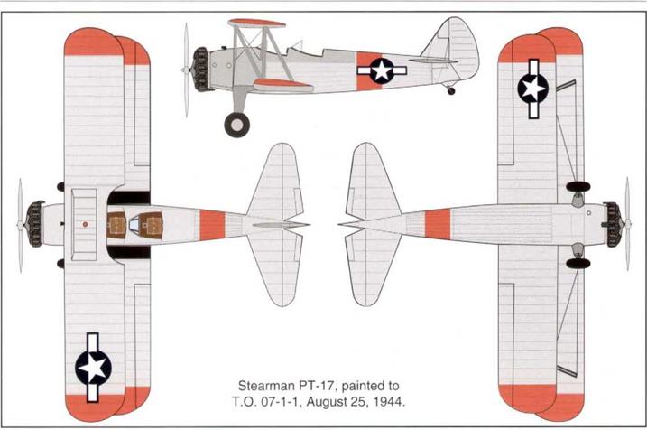
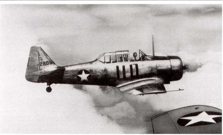
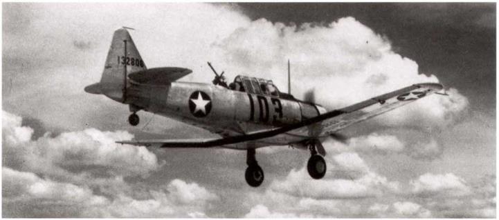
b. FINISHES,—All trainer aircraft will have aluminized finish, except those being by construction having an Alclad alloy finish. (See figure 8.)

c. APPLICATION OF FINISHES.

(1) Подпись:
image206Anodized alloy and miscellaneous steel parts may have two coats of aluminized lacquer, if neces­sary to match surrounding parts.

image207

Vultce ВТ-13, school aircraft “Y-295”, in natural metal finish, shows the lack of a fuselage insignia. The cowl is finished in red and while horizontal hands, below the black anti-glare panel. (USAF via Gerry R. Markgrafl

(2) All other exterior metal surfaces will be finished with one coat of zinc chromate primer, Specifi­cation No. AN-TT-P-656, and two coats of aluminized lacquer consisting of lacquer, cellulose nitrate, class A, clear, Specification No. AN-TT-L-51, with 6 to 8 ounces per gallon of bronze aluminum pigment paste, type B, Specification No. TT-A-468 or AN-TT-A-461.

(3) Exterior plywood surfaces will be finished in accordance with manufacturers’ instructions except that two or more finish coats will be pigmented with 8 ounces per gallon of bronze aluminum, pigment paste, Specification No. TT-A-468 type B, or Specification No. AN-TT-A-461.

(4) All exterior fabric parts will have four coats of clear nitrate dope, Specification No. AN-TT-D – 514. (Aluminized dope vehicle AN-TT-D-551 is not a suitable substitute as it does not have the tautening qualities of AN-TT-D-514.)This will be followed by two or more coats of aluminized dope prepared by adding 6 to 8 ounces per gallon of bronze, aluminum pigment paste, type B, Specification No. TT-A-468 or AN-TT-A461, to dope, cellulose nitrate, clear, Specification No. AN-TT-D-551.

(5) Patching will be accomplished with clear dope, Specification No. AN-TT-D-514 applied in same manner as semipigmented dope previously used.

(6) EMERGENCY REJUVENATOR FOR OLD FABRIC,—To one gallon of 2 to 1 mix of clear dope, Specification No. AN-TT-D-514, and blush retarding thinner, Specification No. AN-TT-T-258, add one fluid ounce each of tricresyl phosphate and castor oil. Apply one coat by brush to clean surface, followed by one spray coat. After several hours’ drying, spray one coat aluminized dope prepared as specified in para­graph 7.a.(4).

(7) For removal of all types of paint material from metal surfaces, use paint and varnish remover, Specification No. 14119. For removal of dope from fabric surfaces, use nitrate dope and lacquer thinner, Specification No. AN-TT-T-256.

d. MARKINGS.

(1) Each part and assembly will be permanently and legibly marked with the same number as the drawing number in such location that it can be read after assembly in the unit. (See Specification No. 98- 24105-Q.)

(2) Various detail and code markings for the cockpit, fuselage, oil lines, etc., as required in Specifi­cation No. 98-24105-Q will be maintained. Use of one coat of varnish, Specification No. TT-V-121 orAN-TT – V-116, for protection of fuselage legend is authorized.

(3) Radio call letters will be used as prescribed in paragraph 3.c.

(4) Painting of ring cowls is authorized in colors as directed by the CommandingGeneral of the Flying Training Command.

(5) Field numbers are authorized as designated by the Commanding General of the Flying Training Command for use in Army Air Forces Training Centers and Civil Flying Schools. They will be of contrasting color, preferably block type, and will be applied to opposite sides of the fuselage between the trailing edge of the wing and the leading edge of the horizontal stabilizer directly in front of the star insignia. The height will be approximately 75 percent of the height of fuselage at that point. (See figure 8.)

e. Standard insignia will be used as prescribed in paragraph 4.

image208

Vultee BT-13,42-42817, aircraft “31?", is seen after the fuselage insignia has been applied. The cowl is yellow’ with a centered insignia blue ring. Note the blue and yellow aircraft next in the lineup. (USAF via Gerry R. Markgraf)

/. All markings and insignia will be made with enamel, Specification No. AN-E-3, insignia colors in oil. Specification No. 3-120, or lacquer, Specification No. AN-TT-L-51.

Lease-Lend aircraft supplied to the Soviet Union during World War II

It is worth mentioning at this point that large numbers of aircraft were supplied to the Soviet Union during the war, under the provisions of Lend-Lease, by the USA and the United Kingdom. Very little was ever released by the Soviet Union on the extent of this help, and in view of the previous entry describing the requirements for camouflage on some of these aircraft produced by Douglas, we are providing a list of the aircraft sent to Russia:

Bell P-39

4,746

Douglas A-20

2,908

Bell P-63

2,400

Douglas C-47

707

Consolidated PBY-6

48

North American T-6

82

Curtiss 0-52

30

North American B-25

862

Curtiss P-40

2,097

Republic P-47

195

This totals more than 14,000 aircraft. In addition, the United Kingdom sent more than 4,500 British designed and built aircraft.

EglLn Field publish report on Glossy Paint for Night Camouflage, December 10,1943.

On December 10,1943, Egiin Field published report No. 3-43-114, “Test of glossy Paint for Night Camouflage”. This stated that compa­rable tests were conducted at Egiin Field with aircraft finished with a special black paint of high specular and low diffuse reflectance and aircraft finished with the standard matt black paint. The matt black aircraft appeared “silvery” white in the searchlights, while the glossy black (622 Jet Black) aircraft was invisible 75% of the time and the effectiveness of both optically and radar controlled searchlights was greatly reduced, except from the specular angle.

The visibility of the glossy black in moonlight was increased over the standard matt black. Waxing or “simonizing” assisted in maintain­ing the effectiveness of this camouflage since a high gloss played such an important part. Egiin Field recommended that the special black paint be standardized and replace the standard matt black

AAFTVaining Command requests return to blue and yellow color scheme for its primary training aircraft, March 1944

On March 25,1944, the CG AAF Training Command wrote to CG, AAF, Washington, DC, stating that they desired to paint the fuselage of all primary trainers blue and the wings yellow This was to improve the visibility of the trainers to decrease the possibility of accidents in flight. A survey they had run showed that many air collisions were being caused by the poor visibility of the silver painted airplanes. Repainting of the aircraft in service could be done over a period of time without interfering with training.

HQ AAF approved the request on May 6, 1944, providing it did not interfere with training operations.

image298

Consolidated B-24H or J, aircraft no.945, “Ruth Ann”, of an unknown aircraft. Probably in Pacific Theater, judg­ing by the aircraft number and background on painting. (USAF via Gerry R. Markgraf)

image299

Consolidated B-24J-125-CO, 42-110037, aircraft IS-B+ of the 700th BS, 445th BG, returns to its base at Tibenham, England, on D-l)ay, June 6, 1044. Everyone is crowding around the aircraft waiting to hear how the invasion is going. (USAF)

New version of T. O. 07-1-1, issued on April 25, 1944, gives instructions for removal of camouflage, at the discretion of the commanders concerned.

This new version of T. O, 07-1-1 was the first to cover the removal of camouflage finishes from aircraft in service anti read as follows (unchanged paragraphs have been omitted):

1. AIRCRAFT CAMOUFLAGE

a. GENERAL. – Camouflaging of the exterior surface of AAF aircraft is hereby discontinued except for helicopters, liaison airplanes, gliders and night fighters and as may be directed otherwise by the Commanding General, Army Air Forces. Aircraft destined for delivery to U..S, Navy and foreign agencies are not included in these requirements. This docs not, however, elimi­nate the required identification data, insignia, antiglare coatings, and corrosion prevention.

b. REMOVAL.

(1) Paint may be removed from presently camouflaged metal aircraft by the operating organizations at the discretion of Com­manders concerned, when local facilities and materials are available, provided no interruption in operations results. Aluminized parts installed on camouflaged aircraft will not be camouflaged. However, when any unpainted metal surface of sufficient area is installed that would materially affect the flight characteristics of the airplane, the remaining camouflage paint may be re­moved. Camouflaged metal parts installed on unpainted airplanes need not have camouflage removed.

image300

Martin B-26B-55-MA, 42-96220, aircraft YA-Q of the 555th BS, 386th BG, Ninth Air Force, makes a smooth landing despite the main landing gears refusing to lower. It is seen at its Great Dunrnow base, England, on June 8,1944. It is in natural metal finish with the invasion stripes very neatly painted around the fuselage letters and star insignia. The unit color hand across the tail is in yellow with black trim. (USAF)

image301

Martin B-26B-L5-MA, 41-31595, aircraft AN-J, “Blazing Heat”, of the 553rd BS, 386th BG ends up on its nose when the nose gear did not function. This shows well (he invasion stripes on the top of the aircraft. The unit stripe on the tail is in yellow. Great Dunmow, England, on June 23,1944. (USAF)

(2) For removal of all types of paint materials from metal surfaces, use paint and varnish remover, Specification No. 14119, in conformance with T. O. No. 07-1-7. If not available, lacquer finishes may be removed with material compounded by the fol­lowing formula: 3 gallons benzene, 2 gallons acetone, and 1 pound of paraffin wax. For removal of dope from fabric surfaces, use nitrate dope and lacquer thinner, Specification No. AN-TT-T-256.

NOTE On airplanes having laminar flow wings, paint should be removed only from the trailing 60 percent of the wings. Sand the edges at the 40 percent chord enough to “feather” but exercise care that the cladding is not removed. Hide the olive drab finish on the leading 40 percent of both top and bottom of the wing with either aluminized lacquer or aluminized varnish as applicable. This is necessary in order that the special putty and surfacer on that portion of the wings be left undisturbed.

See T. O. No. 01-1-140 for information on aerodynamic cleanliness.

image302

Martin B-26B, full serial not known, aircraft YA-V of the 555th BS, 386th BG, shows off the under wing and fuselage stripes. Seen on July 1,1944. (USAF)

image303

image304

Consolidated B-24M-5-CO, 44-41876, aircraft “Lucky Strike”, of the 330th BS, 380th BG. Assigned to the Fifth Air Force in the Pacific, the group was attached to the Royal Australian Air Force until January, 1945. (USAF via Gerry R. Markgraf)

Six Vultee BT-13s lined up at a training school. Only serial visible is on aircraft 40-983, which has a black cowl. Note its aluminized finish over the fuselage and outer wing panels. Other aircraft have yellow, and red cowls, while the last one has a gold band around its cowl. Note the lack of fuselage insignia. (USAF via Gerry R, Markgraf)

image305

Republic P-47D-22-RE, 42-26150, aircraft K4-K of the 510th FS, 405th FG, Ninth Air Force, Seen in early August 1944 at the advanced landing strip A-8, Picauville, Normandy, Stripe across the tail is black and the nose cowl is in blue. The name “Der Jaager” appears to be in white on blue. (William L. Swisher)

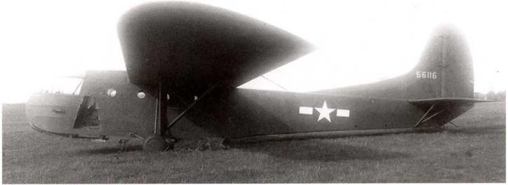
c. FABRIC AIRCRAFT. – Liaison aircraft, helicopters, and gliders still require standard day camouflage. Other fabric covered aircraft and all control surfaces will be aluminized when recovering is necessary,

d. PARTS IN STOCK

(1) Aircraft airfoils and other exterior metal parts in stock need not have the camouflage paint removed.

(2) Fabric control surfaces in stock, or installed as replacements, need not be refinished for any color matching purposes.

e. PROPELLERS.

(1) Lustcrless black need not be applied to propellers unless required for antiglare purposes or corrosion resistance; however, the 4-inch yellow tip must be maintained as a safety measure. Repaired hollow steel blades from which any of the protective plating has been removed will be painted as outlined below, to protect against corrosion. Wood propellers will be painted black; how­ever, the 4-inch yellow tip must be maintained as a safety measure.

(2) If lusterless black is to be used for antiglare or corrosion resistance purposes, it will be accomplished by spraying the hub and each propeller blade while in a horizontal position, and retaining the propeller in this position until the paint materials have set. Over one light coat of zinc chromate primer, Specification No. AN-TT-P-656, one light coat black cellulose nitrate lusterless lacquer, will be applied and will extend to within 4 inches of the tip of the blade; this 4 inch tip section will receive one light coat of lusterless yellow lacquer. The propeller will then be checked for balance.

CAUTION Care will be exercised to mask any angular graduations on the propeller hub or blades. The space between the blade shank and barrel will be masked-off to prevent paint from contacting the seals.

(3) When necessary, three and four-blade metal propellers maybe lightly touched up between overhaul periods, while installed on the airplanes, Care will be exercised to apply proportionate amounts of paint to each blade to maintain proper blade bal­ance.

image306

Douglas A-20G-30-DO, 43-9710, aircraft 7X-G of the 645th BS, 410th BG, seen at strip A-8 on August 9, 1944. Marking on the rudder is in black and white, code letters and nose cowls are in white, as is the name “Three” on the nose. Note how the invasion stripes have been painted over on the lop of the fuselage and wings. (William L. Swisher)

Aircraft for Far East Air Force to continue use of camouflage on its A-20, A-26, and B-25 aircraft, March 1945

TI-2094, Add. No. 2, dated March 3, 1945, initiated action for the application of standard camouflage (olive drab and light gray) to all A – 20, A-26, and B-25 aircraft destined for use by the Far East Air Force, at the request of their CG. This required a waiver from Mil. Req. Policy No. 15, dated November 19, 1943. (Note – these aircraft would be finished in Olive Drab ANA No, 613 and Sea Gray ANA No. 603, not the earlier Dark Olive Drab No. 41 and Neutral Gray No. 43.)

image390

Another rare type, this is a Noorduyn AT-16-ND, 43-12888, seen at strip Y-32, Ophaven, Belgium, in February 1945. This was a version of the North American AT-6A, built in Canada, 1,800 being intended Гог Lease-Lend to Britain. Note the invasion stripes still under the fuselage; Swisher has stated that he saw many aircraft still carrying full invasion stripes, or traces of them, until the end of the war, (William L. Swisher)

image391

Convair XP-81, 44-9100, was the first prototype of a new kind of jet fighter. It had a GE 2,300 shp turboprop in the nose to provide endurance and a GE 3,750 lb thrust jet engine in the tail for speed. It made its first flight on February 11, 1945, but was not successful. (Convair)

Waiver issued stating that gliders, liaison aircraft and helicopters, and troop carrier aircraft do not require camouflage any longer, November 1945

Since the war had ended, Procurement Division (WF), in a letter to HQ AAF, dated October 24, 1945, questioned whether camouflage was now required on gliders, liaison aircraft, troop carriers and helicopters, because this required the stocking of camouflage materials. The Production Division (Washington, DC) granted a waiver dated November 14, 1945, stating that those types of aircraft no longer required camouflage, pending revision of Mil. Req, Policy No. 15,

Supplement to T. O. 07-1-1 adds new identification markings for all aircraft operating within the continental United States, November 1945.

The war was now completely over and huge numbers of aircraft were being returned to the US. It would seem that the number of low – flying aircraft incidents was on the rise and as a result, the AAF issued directions in T. О. 07-1-1B, November 6, 1945, for new identifi­cation numbers to be painted on all aircraft (except helicopters and lighter-than-air). These have become popularly known as “Buzz Numbers.” The applicable portions of the supplement read as follows:

NOTE The work directed in paragraphs 17.b. and 17.c. will be accomplished prior to oral (he next 100-hour inspec­tion by all activities within the continental limits of the United States having permanently assigned aircraft.

1. Paragraph 17.b. of T. O. No. 07-1-1, dated 20 July 1945, is hereby revised to read as follows:

image441

Republic XP-84-RE, 45-59475, was the first prototype of the second AAF jet fighter to enter service. It made its first flight on February 28,1946, from Muroc AAB, and was finished in the same manner as the Lockheed P-80A. (USAF)

image442

Northrop XB-35-NO, 42-13603, made its first (light from Hawthorne, California, on June 25,1946. Culmination of Jack North rop’s efforts to produce a large all-wing aircraft, it suffered from major propeller gearbox and propeller problems, which kept it mostly grounded at Muroc AAB. It was natural metal finish all over. (TJSAF)

b. IDENTIFICATION MARKINGS.

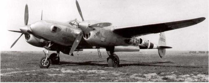
(1) On all aircraft, except helicopters and lighter-than-air, operating solely within the continental limits of the United States, an identification marking will be placed on the lower surface of the left wing, and each side of the fuselage if space permits without relocation of the insignia. These identification markings will consist of two letters and three numerals determined as outlined below. Letters and numerals will be of uniform size, with the letters separated from the numerals by a dash.

(2) The wing markings will be centrally placed on single-engine aircraft and will be placed outboard of engine nacelles on other aircraft, with the top of the letters and numerals forward. The letters and numerals will be of the same height as the wing insignia, with the width at least two-thirds of the height, and the width of each stroke at least onc-sixth of the height.

(3) The exact location and size of the fuselage markings will depend upon the fuselage surface available therefor. Normally, they will be of such size as to cover approximately three-fourths of the surface on which they are placed, but the height of the letter and numerals need not exceed 48 inches. The proportion of the width of the letters and numerals and the width of the stroke to the height will be the same as that of the wing markings in so far as practicable.

(4) The identification markings will be yellow on camouflaged surfaces and black on aluminized surfaces and of either gloss or lusterless enamel or lacquer.

(5) The first letter of the identification marking will identify the type of aircraft, the second letter will be an equivalent for the model number, and the numerals will be the last three numerals of the radio call number. The letters to be used for the various types and models, together with an example of the identification marking of a specific aircraft of each type, are set forth below:

LETTER DESIGNATION LETTER EQUIVALENT

FOR TYPE MODEL FOR MODEL

Attack Aircraft

A

24

A

Example: OnA-26B

A

25

A

marking AF No.

A

26

A

43-22465, the

A

31

A

identification

A

41

A

would be AC-465

Bomber Aircraft

В

17

А

Example: On TB-17F

В

19

В

AF No. 42-3410, the

В

24

С

identification marking

в

25

D

would be BA-410

в

26

Е

в

29

F

в

32

G

В

37

Н

в

39

J

в

42

К

в

44

L

Cargo Aircraft

C

CQ3

A

Example: On C-45,

C

43

B

AF No. 44-47050,

c

45

C

identification marking

C

45

C

would be CC-050

C

46

D

C

47

E

C

48

F

C

49

G

C

53

H

c

54

J

c

60

К

c

64

L

c

69

M

c

74

N

c

78

P

c

82

Q

c

87

R

c

97

S

c

99

T

c

117

U

Photographic Aircraft

F

2

A

Example: On F-5E,

F

5

В

AF No. 44-25908, the

F

6

C

identification marking

F

7

D

would be FB-908

F

9

E

F

10

F

F

13

G

Liaison Aircraft

L

2

A

Example: On L-5, AF

L

3

В

No. 42-15060, the

L

4

C

identification marking

L

5

D

would be LD-060

L

6

E

L

14

F

Observation Aircraft

0

9

A

Example: On OA-I0A,

0

10

В

AF No. 44-34040, the

О

47

C

identification marking :

0

60

D

would be OB-040

О

PB-2B

E

Reconnaissance Aircraft (Excepted)

Gliders (Engine Driven)

G

PG-2

A

Example: On PG-3, AF

G

PG-3

В

No. 45-26888, the

identification marking

would be GB-888

Fighter Aircraft

P

38

A

Example: On P-38J, AF

P

39

В

No, 42-67126, the

P

40

C

identification marking

P

42

D

would be PA-126

P

47

E

P

51

F

P

55

G

P

58

H

P

59

J

P

61

К

P

63

L

P

75

M

P

80

N

P

81

P

P

82

Q

P

83

R

P

84

S

Trainer Aircraft

T

AT-6

A

Example: On AT-11,

T

AT-7

В

AF No. 42-36867, the

T

AT-1

c

identification marking

T

AT-21

D

would be TC-867

T

ВТ-13

E

T

PT-13

F

T

PT-17

G

T

PT-19

H

T

PQ-8

J

T

PQ-14

К

2. Paragraph 17.c. of T. 0. 07-1-1, dated 20 July 1945, is hereby revised to read as follows:

c, Radio call numbers are not required on primary trainers which do not have radio equipment and which bear field identifying numbers; however, identification markings required by paragraph 17.b. are applicable to primary trainers.

White paint tested for use on anti-submarine aircraft, April 1942

On April 9, 1942, tests were run at Halifax, Nova Scotia, to check the visibility of PBY aircraft used for anti-submarine patrol low over water. One PBY was painted flat white, the second was unpainted and the third was in blue-gray finish. It was reported that the test proved unquestionably the effectiveness of white paint on aircraft used for anti-submarine work on sunny days.

As a result, HQ, 1st Bomber Command recommended that camouflage specs, should be changed to provide for the painting of the undersurfaces of anti-submarine aircraft with oyster white lacquer. The necessary materials should be provided to Bomber Command. This recommendation was supported by both the British and American submarine officers.

Further tests were run on April 21, 1942, and it was concluded that a glossy paint might improve the effectiveness, and that de-icer (boots) along wing and tail surfaces also needed to be white. (Note: the request for a white anti-submarine camouflage led to a long, foot­dragging, contest and caused a lot of hard feelings. Not until June 1943, did Materia! Command issue a final report on further tests of the white finish. By that time, it was immaterial, as responsibility for anti-submarine coastal patrols had been handed over to the US Navy. Full details of this can be found in the following pages).

j

11

s ил

гл

image102

Martin B-26B-1-MA, 41-17707, aircraft number 76, was the 164th B-26B of 1,883 built. It is seen painted in the final Sea Search scheme of neutral gray upper surfaces and white lower surfaces. Note the white leading edges of all surfaces. This scheme was developed at Eglin Field. (USAF)

image103

North American XB-28-NA, 40-3056, was developed to replace the B-25, but it was not adopted. It made its first flight in April 1942. The pre­war.’AAF markings are shown on the rudder, together with a very polished natural metal finish. (March AFB Museum)

image104

Three Douglas B-18Bs on anti-submarine patrol in the Caribbean area in the dark olive drab and neutral gray finish. Note how different the color appears on the fabric covered surfaces to that on the metal areas. Both were the same color, but the metal finishes were either enamels or lacquers, while the fabric covering finishes were dopes. This difference in appearance can be seen in photographs throughout the war. (USAF)

Director of Bombardment orders study to determine suitability of white and gray scheme for use by the Anti-submarine Com­mand, November 19,1942

The Director of Bombardment sent a memo to the CG., Anti-submarine Group, on November 19,1942, stating that extensive tests at the Air Force Proving Ground (Eglin Field) had shown that the best type of camouflage for anti-submarine aircraft was:

Ail undersurfaces and surface of airplane that was in shadow should be painted with Insignia White, No. 46, and all other surfaces Neutral Gray No. 43. A picture was enclosed showing the manner in which the two colors should be applied.

He requested that a study should be made as to the suitability of this type of camouflage for use in the Anti-submarine Command. If they had developed a more effective type of camouflage, he requested that they should forward the information as to the type of paint used and a diagram of the scheme used.

On November 23, 1942, HQ., Anti-submarine Command replied stating that extensive testing had been made on camouflage for submarine search, and a report had been submitted on August 31, 1942, to the Commmanding General, Air Forces Eastern Defense Command. The results obtained were varied, but in general the conclusions reached were generally the same as those reached by the Proving Ground. They felt, therefore, that adequate tests had been made, that the camouflage recommended by the Proving Ground be adopted without delay, and that a technical Order be expedited for the camouflage of all Anti-submarine Command aircraft.

On November 30, 1942, the Commanding Officers of the 25th and 26th Anti-submarine Wings were informed that the Dir. of Mil. Req. had issued authority to camouflage all tactical antisubmarine aircraft as follows:

Under Surfaces – Insignia White No. 4 Upper surfaces – Dark O. D. (no change)

They were also informed that a Technical Order would be published in the near future.

image165

Cessna T-50, believed to he NC13, and an unidentified Waco cabin biplane (no NC number visible), were two of the civil fleet of CAA aircraft maintained by Delta Air Lines at Atlanta, Georgia, during the war. Note the star insignia on the fuselage of the T-50. The Waco has a winged insignia and the number “57” on the fuselage. (Delta Air Lines via Talbott)