A cliche that has become firmly set in the public’s mind since the space age began is that space food is a bland, dehydrated mush that comes in a tube. Certainly, for the earliest flights, this was true. However, on Apollo, things began to change a little.
Some of the food taken on Apollo w as dehydrated, for good reason. Water makes up a substantial component of soups and juices, and makes them heavy. Since spare water was plentiful anyway as a by-product of the fuel cells, it made little sense to carry more from Earth. Instead, some food was free/.e-dried, packed into plastic bags and vacuum-sealed to save space. When required, it was retrieved from its storage locker and water was injected through an orifice in the bag. It was then kneaded and left for a few minutes to he fully absorbed. When ready, the corner was cut off with scissors and the contents squeezed out into the mouth.
The Apollo spacecraft had one feature that made eating soups somewhat more pleasurable than on previous spacecraft – hot water. Because the fuel cells had to constantly generate electricity, designers could afford to add a small water heater that could then he used for making coffee and soup. Unfortunately, the limited power available on the lunar module meant that there could be no hot water, and its crews had to spend their lime on the surfaee eating cold food.
On most flights, main meals w’ere similar to modern ready meals, set out in aluminium trays with peel-back lids. Some were kept in a freezer, others in the food stow-age lockers. As a small eleetrie food warmer was provided in the command module, these packages could be heated before consumption. Each meal was planned before the mission, with eaeh crewman choosing what he would like from an available range. Enough food was packed on board to provide each crewman with 2.500 calories daily. For Pete Conrad, the menu for his second day in space w’ent like this: For breakfast, he had apricot pieces, rehydratable sausage patties and scrambled eggs and he finished it off with tw’O rehydratable drinks, grapefruit juice and coffee. At lunchlimc, he heated a tray of turkey with gravy, ate it with four cheese crackers, and downed it with rehydrated orange and grapefruit drink. His evening meal consisted of pork and potatoes which had to be rehydrated, a slice of bread with spread and some sweeties, all washed down with rehydratable cocoa and an orange drink.
On Apollo 8. the crew found an extra treat for Christmas 1968. "It appears that we did a grave injustice to the food people.” said Jim Lovell to Mike Collins in Houston. ‘ Just after our TV show’. Santa Claus brought us a TV dinner each, w’hich was delicious, turkey and gravy, cranberry sauce, grape punch; outstanding.’’ These foil-w’rapped dinners became the norm for Apollo 10 onw’ards. Additionally, the Apollo 8 crew’ found that three small bottles of brandy had been packed among their Christmas food rations. Borman, however, pulled rank and said they could not partake of the brandy until they got home. Being one of the early Apollo flights, almost all their food was in rehydratable form.
’’The food has generally been good.” commented Bill Anders while making audio notes into the onboard tape recorder. "Particularly the last meal: butterscotch pudding, beef stew, grapefruit drink and chicken soup.”
"Well, Bill, you might mention the hot water makes a big improvement, too.” added Lovell. He and Borman had already experienced the longest space mission to date, having spent two weeks in the Gemini 7 spacecraft. Compared to its cramped accommodation, the Apollo cabin wus relatively luxurious, especially the supply of hot water.
Later, during a TV showy Borman and Anders prepared a drink for the camera. "Well, here w-e have some cocoa,” said Anders. "Should be good. I’ll be adding about five ounces of hot water to that. These are little sugar cookies, some orange juice, corn chowder, chicken and gravy, and a little napkin to wipe your hands when you’re done. I’ll prepare some orange juice here.”
Borman picked up the narration. "Okay. You can see that he’s taking his scissors and cutting the plastic end olT a little no/./.le that he’s going to insert the water gun into. The water gun dispenses a half-ounce burst of water per click. Here we go; Bill has it in now, and the water is going in. I hope that you all had better Christmas dinners today than us. but nevertheless, we thought you might be interested in how we eat.”
"Roger.” said Collins at the Capeom console. "I haven’t heard any complaints down here, Frank. We’ll bring you up to speed on your food when you get back. Looks like a happy home you’ve got up there.”
Borman continued. "Ordinarily, we let these drinks settle for five or ten minutes, but Bill’s going to drink it right now. He cuts open another flap, and you’ll see a little tube comes out…”
"This is not a commercial." interjected Lovell.
"… and he drinks his delicious orange drink,” continued Borman. "Maybe 1 should say he drinks his orange drink. He’s usually not that fast. Bill is really in a hurry today. Well, that’s what we eat. Now’ another very important part of the spacecraft is the navigation station or the optics panel. And wc – just a minute; Bill wants to say something.”
“Thai’s good.” said Anders, “but not quite as good as good old California orange juice.”
As Gemini veterans. Pete Conrad and Dick Gordon appreciated the improved culinary features of the Apollo spacecraft. But as they neared the Moon on Apollo
12. A1 Bean had a question for Don Lind, Capeom in mission control. "How about asking the food experts down there, we had a can of tuna fish spread salad last night, and there’s about a half a can left today, and that stuff is still good to eat. isn’t it?”
"We’ll check,” said Lind. "I’ll be right back with you.”
In a moment, the medical doctor occupying the Surgeon console had passed his opinion to Lind w’ho told the crew. "The Surgeon suggests you try a new’ one."
"Well, Dick has this one in his hot hand.” said Bean, "and we just opened it last night. You sure that one isn’t all right?”
The w’heels of mission control w’ere starting to crank up. "We’re still checking with some people down here whether there’s any problem over that tuna fish,” said Lind, "but why don’t you hold off eating it until w’e get a better answ er for you?”
With the flight otherwise proceeding smoothly, managers and backroom people suddenly had a concern and all were keen to come to the correct decision.
"Apollo 12. Houston,” called Lind after 10 minutes had passed.
"Go ahead,” replied Conrad.
"You can’t imagine what consternation your tuna fish question has raised dow? n here. We have a wide diversity of opinion."
Gordon had also been thinking about it. "I decided it was okay,” he said.
"Well, w’e have a vote..said Lind. "The majority says throw’ it aw’ay; there’s a minority report that says everybody can cai ii except Dick Gordon.”
“Okay. That’s done.” said Conrad.
“Roger, d hey recommend that you probably throw it away.” said Lind.
‘•Okay.” * *
Perhaps Gordon got to enjoy his Luna. It is difficult to know. Perhaps he was the butt of inflight banter about his only exercise being between the couch and the food compartment. But the problem was very real. Gordon had trained more than either of the other two crewmen to fly the spacecraft back through the atmosphere at the end of the flight. Had he become ill through bad food, the re-entry would have had to be flown by less experienced crew, and while a normal re-entry w ould have been something Conrad could easily have handled, he simply had not practised for the range of possible abnormal situations that could arise. Л possibly dodgy can of tuna could not be allowed to threaten the mission. They had enough risks to contend with.
The food and drink provided was thought to give the crews everything they w ould need for a flight, but the demands placed on the final three crews showed that this was not so. From Apollo 15 onwards, crews were expected to work for up to seven hours per day on the lunar surface. In preparation, they were intensively schooled in the methods of geology and their missions had much more activity packed into all phases of the flight, ranging from onboard science experiments and advanced photographic mapping operations, to the careful documenting of every rock sample lifted from the dust.
To achieve these enhanced demands, the lunar module crews repeatedly practised the tasks that they would fulfil during their precious few hours on the Moon. As the date of launch approached, much of this training was carried out in the heat of the Florida sun. Apollo 15 w as launched at the height of summer and in the days leading up to its launch, David Scott and Jim Irwin laboured for hours inside their training suits, simulating the techniques that would make their work on the Moon as efficient as possible. Since the cooling systems they would use on the lunar surface could not function in Earth’s atmosphere, this work was hot and demanding. Both men sweated copiously and both drank as much juice as they needed to compensate. On the Moon, as they worked on the plain at Hadley, their heart rhythms were radioed back to the doctor on the Surgeon console at mission control. Towards the end of their lunar stay, he noticed that their hearts occasionally gave an abnormal beat. This was somewhat alarming but the mission objectives had been met and an emergency return would not have been any faster than letting the crew proceed as planned. After their return, further investigation showed that their bodies were lacking in potassium. It had been leached out of their systems by their profuse sweating and imbibing prior to the flight and this had upset their electrolyte balance. It was decided that future lunar module crews would compensate by taking fruit drinks laced with potassium.
On Apollo 16, John Young, who had adopted Florida as his home state, got a little tired of the quantity of potassium-laced orange juice he w as being expected to drink – and the flatulence it was causing. lie began to complain to Charlie Duke about it after their first moonwalk. However, as he spoke, an electronic fault meant that his voice was unexpectedly being transmitted to Earth.
|
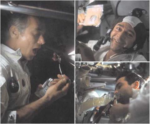
Mealtime in America. Left, Gene Cernan uses a spoon to eat solid food from a bag. Top right, Ron Evans with a vacuum-packed bag of solid food. Bottom right. Jack Schmitt enjoys a drink from a bag while eating food from a can. (NASA)
|
“I have the farts, again,” he moaned. ”1 got them again, Charlie. I don’t know what the hell gives them to me. I think it’s acid stomach. I really do.”
“It probably is,” said Duke.
“I mean, I haven’t eaten this much citrus fruit in 20 years!” laughed Young. “And I’ll tell you one thing, in another 12 fucking days, I ain’t never eating any more. And if they offer to supplement me potassium with my breakfast, I’m going to throw up!” He continued, laughing: “I like an occasional orange. Really do. But I’ll be durned if I’m going to be buried in oranges.”
Apollo 17, like other flights, found that they tended not to eat very much during the coasting phases. The relative inactivity and the weightless environment reduced their calorie needs and their appetite. When mission control asked for an update on what they had eaten, it was partly to enable John Zieglschmid at the Surgeon console to check that the crew could maintain a proper balance of electrolytes in their system in the light of Apollo 15’s problems.
“And are you ready for the trotting gourmet’s report?” asked Jack Schmitt. “Roger,” replied Bob Parker. “Everybody’s here with all ears.”
“Okay,” started Schmitt. “The commander today had scrambled eggs and three bacon squares and a can of peaches and pineapple drink for breakfast. And then later on in the day he had peanut butter, jelly and bread with a chocolate bar and some dried apricots. The LMP had scrambled eggs and four bacon squares, an orange drink, and cocoa for breakfast, and potato soup, two peanut butter and jelly sandwiches, and a cherry bar and an orange drink.” Schmitt then went on to relate what Ron Evans, who had been making a TV broadcast earlier, had eaten. “And that hero of the matinee, the matinee idol of Spaceship America, had scrambled eggs, bacon squares, peaches, cinnamon toast, orange juice and cocoa for breakfast. That’s how he keeps his form. And, for lunch, he had a peanut butter sandwich and citrus beverage. And that’s it, since there’s nobody else up here.”
“Jack, we appreciate all your information,” said Parker, “and we’d like to just pass on some recommendations here from the ground that we’d like you to keep on with your regular menu as much as possible. And, if you do cut anything off, we’d like you to concentrate on eating the meats, the juices and the fruitcake, which are the most effective for maintaining your electrolyte balance.”
Eugene Cernan then piped up. “Okay, Bob. We understand what you’re saying, ft’s just a lot of food, that’s all.”
“Roger. We understand, Gene,” replied Parker. “Also, on that group of foods, peanut butter’s great for the electrolyte balance, also; so you’re doing okay.”
“I knew it was good for something,” said Cernan. “It couldn’t be that good without being good for something.”
Suit food
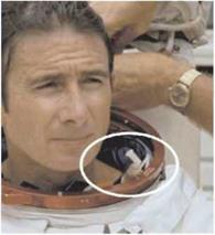 Imagine it. You spend two hours getting into a spacesuit, you go outside into the hardest vacuum possible for seven hours’ hard labour and you need another hour or so to get back out of the suit on your return. While your helmet is on, there is no way to get so much as a hand to your mouth, never mind taking a meal. This was the scenario faced by the J-mission crews, so to ease their inevitable hunger and to provide extra energy for the exertions of working outside, a bar of food was placed inside the neck ring of their suits. Then when the urge took them, they could crane their necks down and chew on it.
Additionally, they had about a litre of water stored in a bag attached to the neck ring of their suits. As he worked outside, a crewman could slake his thirst by sipping through a short tube placed within reach of his mouth.
Apollo 14 used these first, but on Apollo 15,
Irwin’s tube failed, leaving him dehydrated after their first moonwalk. On his subsequent A suited Jim Irwin during training, outings he tried to compensate by drinking His drinking tube can be seen inside
more before and after their time outside. the neck ring. (NASA)


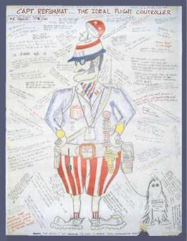 Ed Pavelka was one of the flight controllers who occupied the FIDO console in The Trench at mission control. As a way to cement the esprit de corps among the flight dynamics team, he invented a fictional character called Captain REFSMMAT who represented the ideal flight controller. Urged on by one of his bosses – the tough but sensitive Eugene Kranz – Pavelka imagined a figure of military stature with a radar in his helmet, and drew a series of posters depicting Captain REFSMMAT and his arch enemy, Victor Vector. During the Apol – One of Ed Pavelka’s drawings of Captain lo yearSi pe0ple in the MOCR
 Imagine it. You spend two hours getting into a spacesuit, you go outside into the hardest vacuum possible for seven hours’ hard labour and you need another hour or so to get back out of the suit on your return. While your helmet is on, there is no way to get so much as a hand to your mouth, never mind taking a meal. This was the scenario faced by the J-mission crews, so to ease their inevitable hunger and to provide extra energy for the exertions of working outside, a bar of food was placed inside the neck ring of their suits. Then when the urge took them, they could crane their necks down and chew on it.
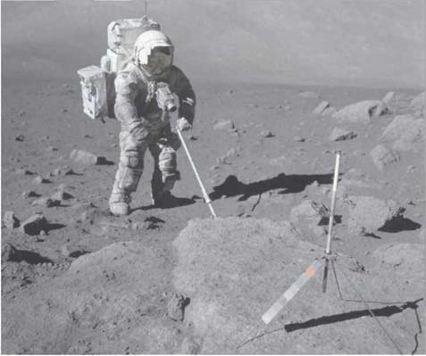
 Eugene Cernan, who commanded the only mission to launch at night, later spoke about having trained to fly his Saturn V to orbit manually, a task no commander wished upon their mission, yet one which appealed to their test-pilot credo. "The launches – both from the Earth and from the Moon – were the only truly automatic phases of the mission, but we could take over and fly it manually to orbit. Aborting during Earth launch was the last thing I wanted to do, so I trained and planned. It was a lot more difficult at night than in the daytime because you didn’t have horizons and things to look at; you had to look at the stars. We had several modes of failure that could have degraded systems. The worst would have been for all the guidance to fail so that you literally had to fly it by the stars.
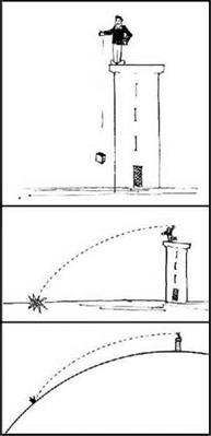 it travels before it impacts Earth’s surface. Let us imagine that this object is a box containing beads, so that the effects of weightlessness can be observed, at least from the perspective of our mind’s eye.
 The next case for our thought experiment above our idealised Earth is where arrangements are made to throw the box at a far greater speed than is achievable by a human arm; say something of the order of a few thousand kilometres per hour. Traditionally in these kinds of mind games, this can be achieved by an immense, imaginary cannon. Once the cannon has done its rather violent job of quickly accelerating the box, we see the same two influences affect the box’s flight. Gravity accelerates the box and its beads down to Earth while the constant horizontal speed takes it away towards the horizon. Again the result is a curved path to the surface. Once the beads within the box have recovered from their sudden acceleration, they are once more seen to float freely and exhibit what we call weightlessness. However, on this occasion, the flight lasts rather longer than in the previous cases. The box’s horizontal speed is so great, and so much distance is being gained as it drops, that by the time it has fallen the height of the tower, the curvature of Earth has dropped the surface level a little, and so the box has further to fall to reach the surface.
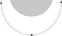 Continuing with our thought experiment, there is a specific case with a slightly higher starting speed than the previous example, where the box maintains a constant altitude. The curvature of Earth’s surface is falling away in exact sympathy with the box’s path, making the two concentric and the orbit becomes circular at the height of the tower. Again, the beads float around weightless within the box, and again, our space – suited experimenter needs to keep his head down as the box will whizz by in about 90 minutes.
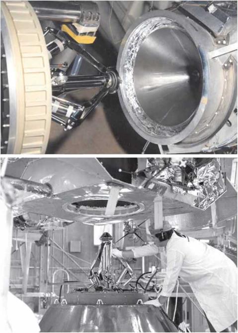
 The crew could see the scratches on the drogue’s surface where the probe had been guided into the hole but there was no obvious reason why the two ships were not holding. As they waited for the controllers and engineers in Houston to assess the situation, they were treated to a spectacular display of countless liquid droplets shimmering before them as the S-IVB began a planned dump of some of its residual propellant. Mitchell enthused about the sight as they drifted among the particles of propellant all around them. “Of course, it’s the source of another ten million particles floating out in front of us.”