Category Space Ship One

Rocket-Engine Operation

On November 18, 2003, Scaled Composites qualified a rocket engine in preparation for the first powered flight of SpaceShipOne.

“The nice thing about this particular type of hybrid motor is the nitrous oxide is room temperature in the oxidizer tank in front. It self-pressurizes to about 750 pounds per square inch,” Doug Shane
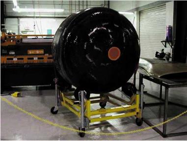
said. This eliminated the need for complicated and expensive pumps to flow the oxidizer into the CTN. In figure 5.15a panel on the belly of SpaceShipOne is removed, exposing the engine bay, so the CTN could be easily mounted.

The oxidizer tank was filled with liquid nitrous oxide through its forward bulkhead. The MONODS pumped the nitrous oxide at 300 pounds per square inch and 0 degrees Fahrenheit. To bring the temperature up to room temperature and maintain it there, engine bleed air from White Knight flowed into SpaceShipOne and was directed at both ends of the tank during captive carry.

The rocket engine of SpaceShipOne could only be fired once. After the rocket engine was armed and the fire switch thrown, the igniter produced a significant amount of heat, causing combustion between the oxidizer and fuel.

“SpaceShipOne does not have a throttle. It is on or off,” Rutan said. “There was no need for a throttle.”

For the spaceflights, the force of thrust was 16,800 pounds-force (74,730 newtons). However, because of performance concerns and

Rocket-Engine Operation

Подпись: ~ J ґ

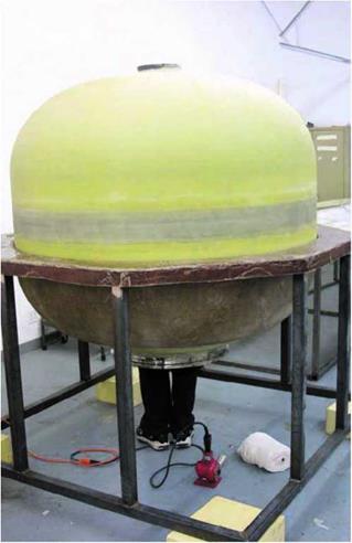
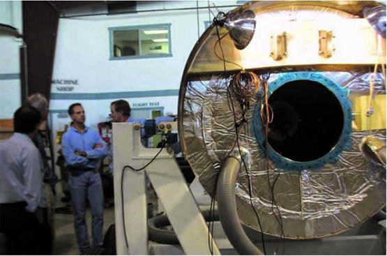
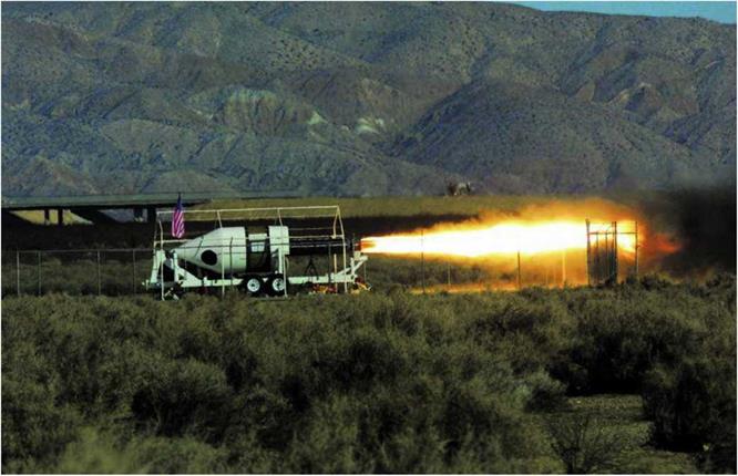
Fig. 5.13. Scaled Composites was able to monitor the performance of each rocket engine tested during the development phase. Data collected by sensors on the TST was relayed to engineers real-time for analysis. Mojave Aerospace Ventures LLC, photograph by David M. Moore

к_________________________________________________________________________________________

Rocket-Engine Operation

Rocket-Engine Operation

г ; ^

Fig. 5.15. Between each spaceflight, it was necessary to replace the spent CTN with a fully fueled CTN. The spent CTN can be refurbished by refueling the rubber inside the casing and replacing the ablative nozzle. Mojave Aerospace Ventures LLC, photograph by Scaled Composites

( >

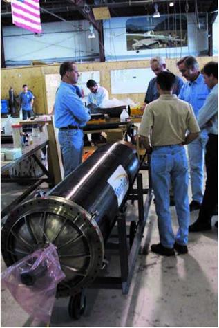
Fig. 5.14. This photograph shows the rocket engine before the engine

fairing was attached. The cantilever rocket-engine design patented by Scaled Composites had the CTN fixed to the oxidizer tank at one end but completely unsecured at the nozzle end. Mojave Aerospace Ventures LLC, photograph by Scaled Composites

V__________________________________________ J the additional payload required by the Ansari X Prize competition, additional nitrous oxide oxidizer and rubber fuel were added, as well as an increase in burn duration. The thrust and the specific impulse (I$p), a measure of efficiency of the rocket engine, were not officially released by Scaled Composites.

Peak performance occurred once the rocket engine ignited. As the rubber burned away and the oxidizer tank emptied, the amount of thrust gradually reduced.

About sixty seconds into the burn, the nitrous oxide began a transition from liquid to gas because there was more room in the oxidizer tank for it to expand, which caused a significant decrease in thrust. At this point, the combustion was uneven throughout the CTN and caused SpaceShipOne to chug along for about five seconds. The ride then smoothed out for the remainder of the burn now that the nitrous oxide had transformed to gas.

During the flight, the engine performance and parameters could be monitored in the cockpit by the pilot and on the ground in Mission Control.

Rocket-Engine Operation

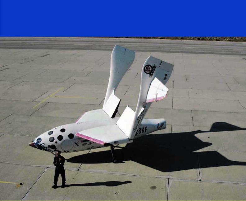
Brian Binnie stands in front of SpaceShipOne with its feather extended. In addition to the feather, SpaceShipOne required three other systems for control during a spaceflight: the mechanical flight control system for subsonic speeds, the electric flight control system for supersonic speeds, and the reaction control system (RCS) for space. Mojave Aerospace Ventures LLC, photograph by Scaled Composites


Rocket-Engine Operation

SpaceShipOne Instruments and Controls

paceShipOne is part airplane, missile, spacecraft, and glider. Like the North American X-1S, it was flown by hand. Figure 6.1 shows SpaceShipOne during a glide test flight with its control surfaces clearly visible on the tail booms.

To complete each spaceflight mission, it had to transition between a variety of flight phases, including takeoff, captive carry, boost, coast, feather, glide, approach, and landing. Flying these phases, SpaceShipOne crossed between three distinct flight regimes: subsonic, supersonic, and zero-g. Different flight control systems were required to operate in each regime. A basic mechanical control system was used in subsonic flight, while an electric – powered control system and a reaction control system (RCS) were required in supersonic and zero-g flight, respectively.

SpaceShipOne had a set of instruments and controls for each flight control system that the pilot had to switch between. Figure 6.2 shows Mike Melvill in the cockpit holding the control stick of SpaceShipOne with the nose cone detached.

Subsonic Flight Control

SpaceShipOne essentially flew like a light airplane—some of the time anyway. It had a mechanical flight control system that operated manually, similar to that of a Cessna 172 or Piper Cub. A simple cable-and-rod linkage tied the stick and rudder pedals

Rocket-Engine Operation

Подпись: Г

Rocket-Engine Operation

г ^

Fig. 6.1. SpaceShipOne was the first manned aircraft to use tail booms attached to the wingtips. Unlike almost every other aircraft, the wings had no control surfaces. The pilot maneuvered SpaceShipOne with control surfaces that were all located on the tail booms, an upper and lower rudder at the back of each tail boom, flying or movable horizontal stabilizers, and elevons at the trailing edge of each horizontal stabilizer. Mojave Aerospace Ventures LLC, photograph by Scaled Composites

Fig. 6.2. With the nose cone detached, Mike Melvill gets some practice at the controls of SpaceShipOne as Steve Losey, the crew chief, looks on. SpaceShipOne had room for a pilot up front and two passengers in the back row. Mojave Aerospace Ventures LLC, photograph by David M. Moore

N

to the control surfaces. The connections between the pilot’s controls in the cockpit and the control surfaces are shown in figure 6.3. No hydraulics were used for flight control.

All of the control surfaces were located on the tail booms. An upper and lower rudder were mounted at the end of each tail boom. The rudder pedals in the cockpit moved the upper rudders for control of yaw. Refer to figure 6.4 for SpaceShipOne s flight axes and rotations. Each rudder pedal worked independently and deflected the corresponding upper rudder outward only. By depressing both, the upper rudders acted a little bit like a speed brake.

On the horizontal stabilizer, elevons combined the functions of conventional ailerons on the wings and elevators on the tail. The control

f ‘ ^

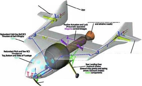
Подпись:Подпись:Подпись:Rocket-Engine OperationFig. 6.3. This diagram shows the different control systems and the linkages from the controls in the cockpit to the control surfaces. The reaction control system (RCS) and the landing gear are also shown in this cutaway. Mojave Aerospace Ventures LLC, provided courtesy of Scaled Composites

V________________ )

Подпись: Not# Skid (Aids runway braking extends only, gravity and spring driven, crush damper) components

f >1

Fig. 6.4. Each of the three flight control systems allowed SpaceShipOne to maneuver along the flight axes. Pitch and roll were controlled by the elevons at subsonic speeds and by the movable horizontal stabilizers at supersonic speeds. The upper rudders and lower rudders controlled yaw at subsonic and supersonic speeds, respectively. RCS thrusters mounted on the wings and fuselage controlled pitch, roll, and yaw in space. James Linehan

V__________________________________________ J

Rocket-Engine Operationf Л

Fig. 6.5. At the trailing edge of each horizontal stabilizer was an elevon. When both elevons moved in the same direction, the pitch of SpaceShipOne changed. When moved differentially, roll changed. The photograph shows the poor airflow over a horizontal stabilizer during a stall test, as indicated by the small strings attached to the surface. Mojave Aerospace Ventures LLC, video capture provided courtesy of Discovery Channel and Vulcan Productions, Inc.

V______________________________ J

stick moved the elevons, which allowed the pilot to control pitch and roll of SpaceShipOne. Figure 6.5 shows a horizontal stabilizer during testing after modification.

Breaking the Sound Barrier (11P)

On December 17, a flimsy aircraft that no one thought would fly prepared to launch from sand-swept dunes. This wasn’t the Mojave Desert, though. It was 1903 in Kitty Hawk, North Carolina. The Wright brothers proved that a couple of bicycle makers could accomplish the unbelievable—powered, controlled, and sustained flight. Their famous flight is shown in figure 8.1.

One hundred years later, to the day, Scaled Composites also looked to make the unbelievable believable. SpaceShipOne was ready for its first rocket-powered test flight.

The sound barrier posed the greatest challenge the team had yet to face. The choice of pilots was not a straightforward one. Mike Melvill, the most experienced test pilot with Rutan designs, had already piloted SpaceShipOne seven times. Pete Siebold and Brian Binnie had each only flown SpaceShipOne once. During such a critical junc­ture, the test pilot with the greatest stick tim SpaceShipOne would seem like the most likel candidate. But Binnie was selected. The entire fate of Rutan’s space program now rested in his hands.

Flight Test Log Excerpt for 11P

Date: 17 December 2003

Flight Number Pilot/Flight Engineer

SpaceShipOne 11P Brian Binnie

White Knight 43L Pete Siebold/Cory Bird

Objective: The eighth flight of SpaceShipOne and first powered flight, fifteen-second burn of the rocket motor and supersonic flight. Motor light-off at altitude and inflight engine performance. Vehicle handling qualities through transonics and feather performance from altitude.

One of the most obvious reasons for the selection was Binnie’s experience flying supersonic jets for the U. S. Navy. “I would suspect that certainly was part of the thinking that went into it,” Binnie said. “I was also kind of the anointed test director for the rocket motor. So, I was very familiar with all the ins and outs with the motor and its performance. I was comfortable with its design and robustness and performance, more so than perhaps anybody else. And perhaps I had, right from the first time I saw it fire, this image in my mind of how it would play out when put into a vehicle. I was very motivated to fly that flight.”

Binnie also had flown Roton, a spaceship prototype produced by Rotary Rocket, Inc., that was half rocket and half helicopter. “That vehicle was decidedly scary to fly,” Binnie said. “I flew it three times. I thought, ‘You know, if I have to do this one or two more times, I’m pretty sure I’m going to kill myself.’ I was honestly sort of fearful that I’d climb into this thing and not climb out. I never felt that way with the spaceship. There were certainly things that could go wrong that could cause an accident, but I never felt that the accident was going to be life threatening.”

With Pete Siebold flying White Knight, Cory Bird released SpaceShipOne at 47,900 feet (14,600 meters). Dropping down, Binnie stabilized SpaceShipOne and started to pull the nose up.

“We knew very little about it. It was all about risk. Our standard for success was, literally, if the rocket motor lit off even for just a few seconds and we shut it down, we were going to call that a success,” Binnie said.

How would the rocket engine function? Would SpaceShipOne hold together during the enormous acceleration? What about the messy transonic region? How about the cockpit? Would it shake too much or be too loud to operate the vehicle? How would the untested controls work at supersonic? Would SpaceShipOne climb quickly enough so that an overspeed didn’t rip it to pieces?

“This was the riskiest flight of our whole program, probably times five or ten,” Doug Shane said.

At 44,400 feet (13,530 meters) and flying Mach 0.55, Binnie lit the rocket engine. “It’s a real rush to kind of ride something that powerful. Like I said, it is like a tsunami comes through the cabin. You are just taken away. So, it is very exhilarating,” Binnie said.

As SpaceShipOne rocketed upward, it broke the sound barrier after only 9 seconds. Figure 8.2 shows SpaceShipOne’s rocket engine firing.

Binnie shut down the rocket engine after a burn duration of 15 seconds as SpaceShipOne hit a maximum speed of Mach 1.2 (800 miles per hour or 1,290 kilometer per hour) while having pulled more than 3 g’s. As SpaceShipOne became the first manned vehicle to have ever used a hybrid rocket engine, it pointed up at 60 degrees and still climbed. SpaceShipOne continued to coast upward and was upside down by the time it reached near-weightlessness at an apogee of 67,800 feet (20,670 meters). Binnie then descended for about a minute with the feather deployed and retracted it at 35,000 feet (10,670 meters).

“It was manageable,” Binnie said. “It wasn’t the most graceful flight. If you looked at it from inside the cockpit, there were a lot of snakes being killed. The boost part of it went extremely well, all things considered, and gave us a lot of confidence that we had a design that was capable. It was only the landing that marred an otherwise wonderful day.”

Breaking the Sound Barrier (11P)

Г ^

Fig. 8.2. Brian Binnie took the controls of SpaceShipOne for test flight number 11P, one hundred years after the flight of the first successful airplane, in which the 1903 Wright Flyer had flown for 12 seconds. Even though Binnie burned the rocket engine for only 15 seconds,

SpaceShipOne broke the sound barrier after only 9 seconds. Mojave Aerospace Ventures LLC, video capture provided courtesy of Discovery Channel and Vulcan Productions, Inc.

ч___________________ ;______________________ J

Breaking the Sound Barrier (11P)

c ^

Fig. 8.3. A crash landing blemished an otherwise successful first rocket – powered test flight. SpaceShipOne touched down harder than the landing gear could handle, causing the left rear main landing gear to collapse and SpaceShipOne to skid off the runway. Mojave Aerospace Ventures LLC, video capture provided courtesy of Discovery Channel and Vulcan Productions, Inc.

v__________________________________________ J

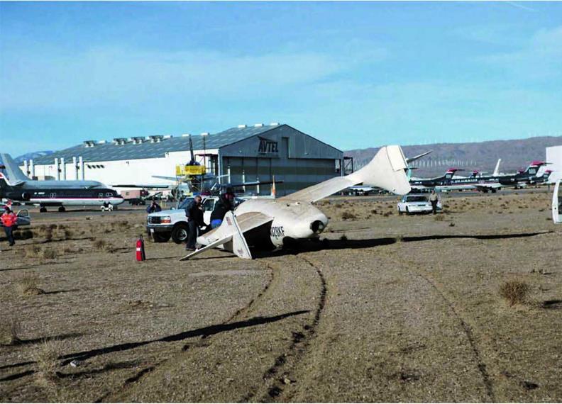
On the landing, which had proved to be a surprising and persist­ent source of trouble for Scaled Composites, SpaceShipOne hit very hard. The left main landing gear collapsed, and SpaceShipOne skidded to the left and off the runway into the dirt, as shown in figure 8.3 and figure 8.4.

Burt Rutan gave some clarification about the cause of the crash landing during a press conference late in 2004. He said, “We were testing at that time, a flight control modification that would give us a better margin on flutter in the transonic area. And that damper in the flight controls had gotten so cold that the controls were extremely sticky. That landing wasn’t Brian’s fault. It was the fault of us not doing the proper thing, and that is put­ting a heater on the damper so that it didn’t freeze up on him on the landing approach.”

Breaking the Sound Barrier (11P)
As Binnie was flaring up for the landing, the damper unfroze. The controls buffeted like SpaceShipOne was going to stall. It was actually just the control linkages responding differently, but there was no way that Binnie could have known this. So, he dropped the nose to prevent the stall that he thought was about to occur. As a result, SpaceShipOne came in too fast and too hard for the fragile landing gear.

Supersonic Flight Control

Similar to the Bell X-l, as shown in figure 6.6, which in 1947 was the first aircraft to break the sound barrier, SpaceShipOne used elec­tric, motor-driven control surfaces to maneuver. After SpaceShipOne
broke the speed of sound during test flights, the subsonic flight con­trols no longer functioned efficiently.

“Once you are supersonic, the control system that you normally use to fly the airplane doesn’t work anymore,” Melvill said. “Because it is a mechanically controlled airplane, there is no hydraulic system like there is on an F-16 or F-l 8. It is just cables and pushrods. You are just not strong enough to move the controls at that point. So you just revert to using the trim switches.”

Supersonic Flight ControlГ"

Подпись:Fig. 6.6. Because the forces pushing against the control surfaces of the X-1 were so strong while flying at supersonic speeds, the pilot could not use conventional mechanically linked flight controls. The control surfaces had to be electrically controlled and moved using electric motors. SpaceShipOne used a similar system for flying above Mach 1. NASA-Dryden Flight Research Center

V________________ J

Many aircraft have trim controls that help the pilots maintain course by slightly altering control surfaces. By changing a trim setting, a pilot can fine-tune the control surfaces, so less force has to be applied to the control stick and rudder pedals in order to stay on course. SpaceShipOne uses trim controls in a somewhat similar way during supersonic flight.

A switch on the top of the control stick activated electric servos that pivoted the entire horizontal stabilizer on each side of SpaceShipOne for pitch trim. In figure 6.7, a close-up of a tail boom shows the numeric scale that indicates the amount of deflection for the horizontal stabilizer as set by the pilot.

Supersonic Flight Control

r ; ^

Fig. 6.7. Triangular strakes were added in front of the horizontal stabilizers, which were also enlarged, to improve the aerodynamics of SpaceShipOne. The numbers to the right of the strake show the amount of trim or deflection of moveable horizontal stabilizers. Mojave Aerospace Ventures LLC, photograph by David M. Moore

V__________________ J

A knob at the pilot’s left side called the “turtle” activated the lower half of each rudder, giving yaw trim. “Yawing the airplane caused it to roll because of the high wing and the swept leading edges,” Melvill said. “We actually didn’t use the roll trim. It was too powerful. We used yaw trim to roll the plane. If it was rolling off to the left, you would yaw it to the right.”

The lower rudders were synced and moved in the same direction, unlike the upper rudders used in subsonic flight. “The geometry is such that they go out a lot and in just a little bit,” Rutan added. “But they never work opposite.”

Trimming was also used to restrict the movement of SpaceShipOne during test flights. For example, when Mission Control monitored the trajectory of SpaceShipOne, they would instruct the pilot to make trim changes in order to help him stay on course.

More than midway through the burn, the atmosphere became so thin that the supersonic flight controls were no longer needed. The pilot was able to control SpaceShipOne with subsonic flight controls, even though it was flying much faster than the speed of sound, because the rarified air produced little opposing force. When SpaceShipOne fully left the atmosphere, the pilot then switched over to the RCS.

Unplugged (12G)

After a little less than three months, SpaceShipOne was ready to return to the air again, with Pete Siebold at the controls. However, its rocket engine would be quiet during this test flight.

“It was after the famous 11P flight, which resulted in significant damage to the aircraft on the hard landing,” Siebold recalled. “It was

Unplugged (12G)Unplugged (12G)in one respect what we would call a functional check flight after any major modifications to the airplane. We wanted to go fly it in a semi – benign environment and try and shake down any of the problems that we may have overlooked or additional problems that had been created due to the modifications.

“The other reason was we made some modifications to the aero­dynamic shape. We added the thermal protection to the aircraft. If you look at the artwork of that flight, it shows the red leading edges and shows the TPS addition. That actually changed the wing shape slightly and the aerodynamic shape. So, we wanted to go and fly that and see if there were any ill effects to that modification for the flight.”

Siebold started off his second time flying SpaceShipOne at an altitude of 48,500 feet (14,780 meters), which was the highest point that White Knight ever released SpaceShipOne. Scaled Composites had originally planned on releasing SpaceShipOne from an altitude of 50,000 feet (15,240 meters). However, White Knight had a very difficult time flying this high and too frequently had come out of afterburners or flamed out altogether at an altitude even below this one. The lower launch altitude did actually work in SpaceShipOne’s favor.

During powered flight, the first thing that SpaceShipOne had to do was “turn the corner” as soon as it possibly could, but the higher the altitude, the less air there was for the wings to bite into in order to make a quick turn upward. So, in terms of utilizing the energy from the rocket engine as efficiently as possible, launching below 48,000 (14,630 meters) feet gave better overall performance, since SpaceShipOne would spend more time pointing up than over.

However, since Siebold wasn’t concerned with lighting off the rocket, he wanted all the altitude he could get for the glide flight. “There were some minor glitches,” he said. “The thermal protection system started cracking at low temperatures, and I think there was actually a formulation change made between that flight and the actual powered flight.”

But the thermal protection system (TPS) wasn’t the only system being checked out. Siebold also evaluated the reaction control system (RCS) that would be used to maneuver SpaceShipOne while in the absence of the atmosphere. This and other testing worked out smoothly, and SpaceShipOne touched down safely, even in the presence of a strong crosswind.

Reaction Control System

Because there is no atmosphere in space, the flight control systems that ordinarily allow an aircraft to move through the air do not work for spacecraft moving through space. Rudders, elevators, and ailerons only work because air moves over them. With no air, they are useless.

In order to maneuver in space, spacecraft take advantage of a simple physics law discovered by Sir Isaac Newton:for every action, there is an equal and opposite reaction.

Without considering a spacesuit, for example, if a person was in space and blew through a straw, the air would move out the straw in one direction and the person would move in the opposite direction.

Figure 6.8 shows an astronaut with a hand-held reaction control system (RCS). To move, he just points the opposite direction, releases a puff of gas, and off he goes in the direction he wants. This, by the way, is the same principle by which a rocket engine works. The RCS thrusters are just miniature rocket engines.

Reaction Control System( ■ >1 Fig. 6.8. In Gemini 4, astronaut Ed White made the first U. S.

spacewalk. To maneuver during his 23-minute extravehicular activity

(EVA), he used a hand-held self maneuvering unit (HHSMU) that shot

little bursts of gas, which allowed him to move around. This device

worked similar to the way SpaceShipOne’s reaction control system works.

NASA-Johnson Space Center

к_________________________ J

The Space Shuttle uses a fuel of monomethylhydrazine (MMH) and an oxidizer of nitrogen tetroxide (N204) for its RCS. These pro­pellants react together spontaneously once in contact. As long as each chemical is stored safely separate, they provide the orbiter a simple, reliable, precise, and powerful RCS.

SpaceShipOne had limited time in space and was much less massive than the Space Shuttle. The force generated by these expensive and toxic chemicals was not required. So, puffs of air were sufficient to maneuver SpaceShipOne in space.

After the aerodynamic control authority was gone, the pilot used the RCS to help slow down or null any rotation that had developed while exiting the atmosphere. Each wingtip had roll thrusters, and along the top, bottom, and sides of the fuselage were pitch and yaw thrusters. Each of these thrusters was essentially a port from which high-pressure air could be expelled, and each thruster had a backup. Redundant 6,000-psi bottles of air powered the RCS. By fully extend­ing the rudder petals and the control stick, the pilot maneuvered SpaceShipOne by triggering microswitches that turned the appropriate thrusters either full-on or full-off.

The RCS was also used to get into position for reentry. Scaled Composites had confidence that the feather would self-right SpaceShipOne. However, they did not want to start off upside-down if they didn’t have to.

Tier One Navigation Unit

The pilot had to fly a specific trajectory carefully during a mission. If he deviated, he risked not only failing to reach the target altitude but also missing the prescribed reentry area or, in the extreme case, being too far away from the landing site.

“The aircraft itself was completely manually controlled,” Pete Siebold said. “So, the only feedback the pilot had to how the airplane was flying was through the avionics system.”

It was necessary to develop an avionics system, called the Tier One navigation unit (TONU), for SpaceShipOne. “There really was nothing available within our budget and nothing available off the shelf that suited our needs. So, we had to go develop it ourselves,” Siebold said. The system navigation unit (SNU) and the flight director display (FDD) were the two primary components that made up the TONU.

“We had contracted a company to basically develop the hardware portion of the nav system,” Siebold said. “They built the boxes and put the computers in. They were initially responsible for developing the software of the navigation system as well. However, we ended up making major modifications to that software at the end of the program to make it perform the way we needed it to perform. On the display side, we wrote all the software for the entire program from the beginning.” Aside from being a test pilot, Siebold was the engineer behind most of the software design. Fundamental Technology Systems (FTS), also an Ansari X Prize competitor, provided the hardware and initial software to Scaled Composites.

Acting as the brain of the TONU, the SNU incorporated both a global positioning system (GPS) and an inertial navigation system (INS). It sent guidance and navigational information to the pilot, who saw it on the liquid crystal display (LCD) screen of the FDD in glass- cockpit-type fashion. The SNU navigates along the primary flight axes in six degrees of freedom: the translations of left/right, forward/back, and up/down and the rotations of yaw, roll, and pitch.

Close-ups of the FDD are shown in figure 6.9 and figure 6.10, which also show the similarity between the cockpits of SpaceShipOne and White Knight.

Fly-by-wire was not an option. Siebold said, “It wasn’t warranted for the complexity of this program. Fly-by-wire adds a whole order of magnitude to the whole vehicle development costs. And we really wanted to keep this as simple as possible in order to make this affordable for everybody. That is really the backbone of this program. If you can make it as simple as a Volkswagen, then everybody can afford it. If it needs to be as complex as the Space Shuttle, then nobody can afford it. We really had to push really hard toward making it affordable from the onset.”

The data available to the pilot is based on several modes that correspond to the different phases of flight for SpaceShipOne. Figures 6.11 to 6.14 show various FDD modes, including a boost, a reentry, and a glide. In these modes, the pilot is given trajectory guidance with respect to a detailed map that tracks the position of SpaceShipOne. The FDD automatically stepped through the different modes while flying the mission, but a control allowed the pilot to manually move through the modes in the unlikely event he needed to do so.

Siebold said, “We had the initial boost portion. So, that was the pull up. Then it transitioned to a pseudo-boost mode were every­thing zoomed in and allowed you to track your final target, fly that

Reaction Control System

г ; л

Fig. 6.9. A close-up of the flight director display (FDD) for SpaceShipOne is shown in this photograph. The FDD was part of the Tier One navigation unit (TONU) and provided the test pilot with instruments similar to the way a glass cockpit does for an airliner.

Mojave Aerospace Ventures LLC, photograph by David M. Moore

V_____________________________________ J apple onto your target. Once the motor shut down, it transitioned to a coast phase. Once you left the atmosphere, it transitioned into a reentry phase. Once you reentered, it transitioned into three different glide phases. We called them high key, final, and landing phase. And those three phases helped you to find your way back to the airport, and manage your energy so that you’d end up touching down at the place you wanted.”

Sometimes SpaceShipOne nearly pointed straight up, and sometimes it was upside-down. The attitude, or orientation, of SpaceShipOne in flight was key flight information provided on the FDD. “It showed you whether or not you are at wings level,” Siebold explained. “One unique aspect of the display was that as you pitched the nose up, when the horizon on the display disappeared, it still gave you situa­tional feedback to tell you what attitude the aircraft was in.”

A second key piece of flight information was the velocity vector. “What that tells you,” Siebold said, “is the direction in which you are currently flying—the direction in which your velocity is currently heading. That was depicted on the screen with what we called the green apple. It was a green circle with a tail and two wings pointing out of it.” So, with the pilot knowing how SpaceShipOne was oriented and how it was moving in flight, the FDD offered two other bits of crucial flight information. These were the location of the optimum trajectory, represented by the “red donut,” and where SpaceShipOne was with respect to it, which was the “green apple.”

In a presentation at NASA Ames, Doug Shane had given the follow­ing succinct description: “The goal is to take that green velocity vector and put it right over that red donut, because that is the flight-director cue. And that gets you to the reentry point that you want. Very simplemindedly, your task is only to get those two circles closed up as quickly as you can. And that establishes essentially a vertical trajectory and gives you the best performance that you can get.”

In addition, the SNU monitored and recorded how the systems of SpaceShipOne were performing and fed this information to the FDD, where it was displayed. “It acted as a caution/warning/advisory system,” Siebold said. “It told you if there is any parameter out of limits, or if

Reaction Control System

Ґ ^

Fig. 6.10. The inside of White Knight’s cockpit, shown here, is remarkably similar to the cockpit of SpaceShipOne. Even the instrumentation and controls are nearly identical, with the obvious exception that SpaceShipOne has rocket-engine controls and White Knight has jet-engine controls. Since White Knight started flying about a year before SpaceShipOne, this allowed Scaled Composites to build up confidence in the instruments prior to flying SpaceShipOne. Also, White Knight could be used as a trainer for SpaceShipOne. Mojave Aerospace Ventures LLC, photograph by Scaled Composites

v___________________ J

there is anything out of limits that would cause you to abort the flight. We had a small list of parameters that if they ever exceeded some allowable range, they’d flash a big red sign that said ‘abort.’”

During the rocket engine burn, things happened fast. There was not a lot of time to make decisions. The TONU did not automatically control SpaceShipOne. “The pilot still had to look at the information, digest it, and make the appropriate decision with that information,” Siebold said.

Data that the SNU collected then displayed to the pilot on the FDD was also transmitted real-time to Mission Control on the ground by a radio frequency (RF) telemetry downlink. In Mission Control, the data reduction system (DRS) collected, processed, and stored all the trans­mitted data and made it accessible to everyone in Mission Control.

A Third of the Way There (13P)

Why did the desert tortoise cross the runway? Now that Scaled Composites planned a longer burn, it could no longer fly under the radar of the FA A. Scaled Composites needed a commercial launch license, and the Office of Commercial Space Transportation (AST) of the FAA required Scaled Composites to do an environmental impact report as part of the application process.

Doug Shane explained, “One of the caveats that came back with that [application] is before taking off in White Knight and before landing in SpaceShipOne, we had to do a sweep of the Mojave runway for desert tortoises. And if we found a desert tortoise, we couldn’t move it. We couldn’t touch it. We couldn’t talk to it. We couldn’t negotiate with it. We couldn’t threaten it. We couldn’t bribe it in any way.

“What we had to do was call the desert tortoise control specialist from Ventura County, about a three-hour drive away, and let them come and negotiate some kind of a successful conclusion.”

Ґ————————————————————————– A

Flight Test Log Excerpt for 12G

Date: 11 March 2004

Flight Number Pilot/Flight Engineer

SpaceShipOne 12G Pete Siebold

White Knight 49L Brian Binnie/Matt Stinemetze

Objective: The twelfth flight of SpaceShipOne. Objectives included: pilot proficiency, reaction control system functionality check, and stability and control and performance of the vehicle with the airframe thermal protection system installed. This was an unpowered glide test.

(source: Mojave Aerospace Ventures LLC, provided courtesy of Scaled Composites)

v___________________________________________ 7

Fortunately, Scaled Composites got their license, no tortoises made runway excursions, and flight 13P was a go. Pete Siebold, who would have the controls of SpaceShipOne for the second power flight, recalls, “That was the first time that we flew basically at our heavy weight. First time we put all the nitrous on board. The airplane was fully ballasted to be a representative weight for the spaceflights. It was part of that incremental weight expansion.”

Right upon release from White Knight at 45,600 feet (13,900 meters) and 125 knots, though, SpaceShipOne ran into problems. “We pulled the nose up to maintain our speed, and we realized that the wings at that weight and speed could not lift the vehicle,” Siebold said. “So, the wings were stalling earlier than anticipated. So, there was this problem that we were faster than we wanted to be to light the rocket, which would result in an overspeed.

But we also didn’t want to abort the flight, because we had some really questionable handling qualities if we dumped all the nitrous to our landing weight. It would send our CG dangerously far aft.”

Flight Test Log Excerpt for 13P

Date: 8 April 2004

Flight Number Pilot/Flight Engineer

SpaceShipOne 13P Pete Siebold

White Knight 53L Brian Binnie/Matt Stinemetze

Objective: The second powered flight of SpaceShipOne. Forty seconds motor burn time. Handling qualities during boost, through transonic and supersonic. Reaction control system functionality inflight and feather configuration stability during transonic reentry. Evaluation of radar tracking capability.

(source: Mojave Aerospace Ventures LLC, provided courtesy of Scaled Composites)

V___________________ J

г >1

A Third of the Way There (13P)A Third of the Way There (13P)Fig. 8.5. Nearly four months after the first rocket-powered flight test, Pete Siebold ignited the rocket engine of SpaceShipOne for 40 seconds and reached an apogee of 105,000 feet (32,000 meters). He hit a top speed of Mach 1.6 on the boost and Mach 0.9 on the way down. Mojave Aerospace Ventures LLC, video capture provided courtesy of Discovery Channel and Vulcan Productions, Inc.

V_________________________________________________ )

Ґ Л

Fig. 8.6. SpaceShipOne reached a third of the way up to the Ansari X Prize goal of 328,000 feet (100,000 meters). This was all part of the incremental testing plan. Although not able to test the feather while moving supersonically, Pete Siebold was high enough to test the reaction control system (RCS). Mojave Aerospace Ventures LLC, video capture provided courtesy of Discovery Channel and Vulcan Productions, Inc.

V

A Third of the Way There (13P)

Ignition was delayed by two minutes as Mission Control tried to decide whether to abort the flight or just to go ahead with the burn.

“One of the benefits we had in delaying was we went to a lower altitude, which would allow us to turn the corner much faster, which minimized the risk of overspeed in starting the flight at a higher than expected airspeed,” Siebold said.

After dropping for more than a mile, Siebold lit the rocket engine at 38,300 feet (11,670 meters). Figure 8.5 shows Siebold during the pull-up after rocket engine ignition.

SpaceShipOne was moving at Mach 1.6 when Siebold shut down the rocket engine after a 40-second rocket burn. The rocket plane reached an apogee of 105,000 feet (32,000 meters), which was about a third of the distance SpaceShipOne needed to climb for the Ansari X Prize. On descent, SpaceShipOne experienced Mach 0.9 while feathered.

The flight overall was a success. Burn duration increased signifi­cantly from the 15 seconds of the first rocket-powered flight.

“We also were able to demonstrate that we could maintain control during the pull-up, which was something on 11P that was sort of in question. Brian was fighting the vehicle trying to keep the wings level. So, overall, I think the only objective that we weren’t able to meet was the supersonic feather reentry” Siebold said.

Figure 8.6 shows Siebold flying SpaceShipOne back to Mojave.

Overall Dimensions

At 28 feet (8.5 meters) in length, 8.8 feet (2.7 meters) in height, and 27 feet (8.2 meters) in width, which is the distance between the tips of SpaceShipOne’s horizontal stabilizers, the spacecraft is only slightly smaller than the Bell X-l. Table 4.1 shows a size comparison between SpaceShipOne, the X-l, the X-l5, and the Space Shuttle. Although the width of SpaceShipOne is slightly wider than the wingspan of the North American X-l5, it is about half the length of the X-l5. Every time SpaceShipOne flew, it had a different weight. The final spaceflight was
the heaviest, with an empty weight of 2,646 pounds (1,200 kilograms) and maximum weight of 7,937 pounds (3,600 kilograms).The weight advantage of SpaceShipOne was clear when compared to the gross weights of 12,250 pounds (5,557 kilograms) and 38,000 pounds (17,237 kilograms) for the X-l and X-l5, respectively.

Energy Altitude Predictor

During the test flight, the TONU displayed a readout from the energy altitude predictor during the boost phase. Developed by aerodynamicist Jim Tighe, it worked by making calculations based on factors like SpaceShipOne"s speed and thrust. The pilot used this to decide when to turn off the rocket engine because SpaceShipOne was roughly half the distance to apogee after rocket-engine shutdown. For the second half, it coasted the rest of the way up.

The pilot needed a way to ensure he didn’t run the rocket engine too long or too short. The initial powered flights relied on a timer, but using the energy altitude predictor yielded much better results. By looking at the readout of the energy altitude predictor, the pilot had a very good idea of the altitude SpaceShipOne would reach if the rocket engine shut down at that exact moment.

For example, the energy altitude predictor may have read 200,000 feet (60,960 meters), but in actuality, SpaceShipOne may have only been at an altitude of 80,000 feet (24,380 meters). So, if

SpaceShipOne shut down the rocket engine at that precise moment, it would coast to an apogee of about 200,000 feet (60,960 meters). This would be 128,000 feet (39,010 meters) short of the Ansari X Prize requirement. Therefore, the pilot wouldn’t have shut down the rock­et engine at this point, but he would have waited until the energy alti­tude predictor read at least 328,000 feet (100,000 meters).

Feather at Supersonic (14P)

Nearly one full year since flight testing began, SpaceShipOne was on the verge of making a spaceflight. One critical piece of infor­mation was missing, though. “The object of that flight was to do a supersonic feathered reentry,” Mike Melvill said. “We needed that data before we could go beyond that.” Figure 8.7 shows SpaceShipOne mated up to White Knight in preparation for the third powered flight.

Ten seconds after releasing from White Knight at 46,000 feet (14,020 meters), Melvill lit off the rocket engine. Figure 8.8 shows a dramatic rearward view of the rocket engine’s fiery plume and exhaust.

“During the boost after he reached the vertical part of the trajec­tory, the avionics display started flickering and then went blank,” Doug Shane said. “We all had good displays in the ground station. And Mike said, T looked out the window, and we were going pretty much straight up. So, I stayed with her.’ Gotta love a guy like Mike. Of course it came back on as soon as the motor shut down.”

The rocket engine burn duration was set by a timer. As Melvill looked out the windows to navigate, SpaceShipOne boosted to 150,000 feet (45,720 meters) and Mach 2.5, and then its rocket engine shut down. SpaceShipOne

r————————————————–

Flight Test Log Excerpt for 14P

Date: 13 May 2004

Flight Number Pilot/Flight Engineer

SpaceShipOne 14P Mike Melvill

White Knight 56L Brian Binnie/Matt Stinemetze

Objective: The third powered flight of SpaceShipOne. 55 seconds motor burn time. Handling qualities during boost and performance verification. Reaction control system use for reorientation to entry attitude. Supersonic feather stability and control.

Feather at Supersonic (14P)

"


Ґ

Feather at Supersonic (14P)

Подпись: у
Подпись: Ґ s ^ Fig. 8.8. SpaceShipOne had several video cameras mounted inside the cockpit and on its exterior. This video-capture image shows a rearward view from the top of the fuselage of the rocket engine's plume and exhaust. Mojave Aerospace Ventures LLC, video capture provided courtesy of Discovery Channel and Vulcan Productions, Inc. к ) continued its ascent to an apogee of 211,400 feet (64,430 meters). But since Melvill had lost his avionics during boost, the trajectory was not exactly spot on. “I was doing forward loops, or something, at the top. It slowed down but came back in, and then it was swinging around a lot.” Melvill used the RCS to dampen the oscillations. In the feather configuration, SpaceShipOne reentered the atmosphere at Mach 1.9 and 3.5 g. SpaceShipOne quickly stabilized and made its feathered “carefree”

Fig. 8.7. The photograph shows SpaceShipOne being prepared for its third rocket-powered test flight. SpaceShipOne had made its very first test flight just about a year earlier. The main goal of this test flight was to evaluate the performance of the feather at supersonic speed. Mojave Aerospace Ventures LLC, photograph by David M. Moore

г ^

Feather at Supersonic (14P)Fig. 8.9. SpaceShipOne reached an apogee of 211,400 feet (64,430 meters), and the video camera in the tail boom recorded the feather in the extended position. While high above Los Angeles, SpaceShipOne was technically not in space, even though the curvature of Earth can be clearly seen. However, the curvature is somewhat exaggerated due to the auto focus lens used. Mojave Aerospace Ventures LLC, video capture provided courtesy of Discovery Channel and Vulcan Productions, Inc.

V_________________________________________________ J

Feather at Supersonic (14P)

reentry just as expected. It actually descended more smoothly at supersonic speeds than it did at subsonic speeds. Figure 8.9 shows SpaceShipOne above Earth, with Los Angeles and the California coast­line in the background.

Back on the ground, engineers traced the avionics malfunction to a dimmer, a small electrical component. And since the thermal protection data looked good, Scaled Composites felt that SpaceShipOne performed well enough to continue forward.

Fuselage and Composite Structures

The construction of SpaceShipOne really began with the building of the fuselage. Without its wings and tail attached to the fuselage, SpaceShipOne looks like a stubby little rocket. Figure 4.5 shows the crew compartment in the forward section of the fuselage, the oxidizer tank in the middle section, the rounded pressure bulkhead that separates the crew compartment from the oxidizer tank, and the rocket engine in the aft section. The maximum outer diameter of the cylindrical

Fuselage and Composite Structures

г ^

Fig. 4.5. The cutaway drawing shows the crew positions in the cockpit of SpaceShipOne. A pressure bulkhead separates the crew from the rest of the rocket engine. The oxidizer tank mounted at the center of the fuselage has the rocket engine CTN (case/throat/nozzle) attached directly to it. Mojave Aerospace Ventures LLC, provided courtesy of Scaled Composites

V_____________________________________ )

Fuselage and Composite Structures

f >

Fig. 4.6. A first step in the assembly was to build the carbon fiber/epoxy composite subassemblies that made up the fuselage. The subassemblies were bonded together, except for the nose cone, which was a detachable emergency escape hatch. Mojave Aerospace Ventures LLC, photograph by Scaled Composites

V__________________ )
fuselage is 60 inches (152 centimeters). It is a monocoque design, which means that the fuselage hull provides most of the structural support and load bearing for the spacecraft. However, the rocket engine obviously exerts a tremendous amount of force. So, the oxidizer tank is actually a very important structural member as well.

SpaceShipOne was put together much the same way a small plastic model airplane is put together. Beginning with a bunch of individual parts, they are assembled piece by piece. Woven layers, also called plies, of carbon fiber and epoxy were the primary materials used to make most of the lightweight composite parts of SpaceShipOne. These parts were used to build the fuselage, the wings, and the tail booms.

The whole process began by designing the parts using three – dimensional computer-aided design (CAD). The designs were then fed into an automated computer numerical control (CNC) machine to carefully shape the parts by whittling down foam blocks. Even though these foam parts precisely resembled the actual composite parts, they did not share the same strength, durability, resilience, and imperviousness to temperature. The foam parts were used to create molds that would then be used to create the actual composite parts to build SpaceShipOne.

After the molds were created, lay-up began. Here the composite material was built up layer by layer. Once enough material was added and the layers were to the proper thickness, the parts were vacuum-bagged and oven-cured. The vacuum-bagging process is basically what it sounds like. A part is covered with an airtight bag, which is evacuated by a pump. What this does is remove air from in between the layers and volatile compounds that are in the epoxy, which have become unwanted byproducts. The more thoroughly they are removed, the stronger the composite will be. The oven-curing enables the epoxy to properly set and achieve the desired properties. After the parts for SpaceShipOne were cured, assembly began.

Although the materials may have changed, the building technique was not unlike that used to build European sailplanes over the past forty or fifty years.

The primary structure of the fuselage is made up of only a few very large subassemblies. Figure 4.6 shows the nose cone and cabin section. The subassemblies have edges that fit to one another. They are then fastened with a jig and chemically bonded together. The subassemblies

Fuselage and Composite Structuresr ; л

Fig. 4.7. Piece by piece, the exterior of SpaceShipOne took shape, like the building of a plastic model airplane. As construction proceeded, the wings were attached to the fuselage, and all the wiring, plumbing, linkages, and other components were installed inside. Mojave Aerospace Ventures LLC, photograph by David M. Moore

v________ J

Fuselage and Composite Structures
ґ

Fig. 4.8. Because the cockpit was pressurized and SpaceShipOne faced extreme conditions in space, the walls of the fuselage provided double containment. In between the "shell within a shell" was an insulating layer that also improved the structural strength of the fuselage. Mojave Aerospace Ventures LLC, photograph by David M. Moore

V__________________________________________________________________________________________

Fuselage and Composite Structures

f ^

Fig. 4.9. This photograph shows the early stages of construction for the aft section of SpaceShipOne. A pressure bulkhead will be put in place at about the location of the opening in the fuselage to separate the oxidizer tank from the cockpit. Mojave Aerospace Ventures LLC, photograph by David M. Moore

V____________________________________ J
together form the inner hull or shell of SpaceShipOne. This inner shell is still not strong enough to support the spacecraft.

The nose cone is attached to the rest of the fuselage a little differ­ently. The nose cone is the primary escape hatch. Its edge is keyed so that it can lock and unlock from the fuselage with a quick little turn.

Figure 4.7 shows the cabin section that is forward of the pressure bulkhead in various stages of construction. Figure 4.8 shows the top of the cabin section after even more assembly, and figure 4.9 shows the aft section where the wings mount.

The next step in building the fuselage was to add a core of honey­comb material on top of the inner shell. Nomex, made by DuPont, was used as the honeycomb core. Not only is the honeycomb core lightweight, it offers high strength and it is heat and fire resistant. The honeycomb core, however, cannot serve as the outer layer. It needs further covering. So, panels called skins, manufactured using this composites process, were attached to the honeycomb core. The fuselage is a shell within a shell. The process of adding succes­sive layers creates what is known as a sandwich structure, as the fuselage hull is viewed in cross-section. Figure 4.10 shows an example of a sandwich structure. Another way to look at this is that the fuselage hull is a thick composite made up of several thin composites.

Fuselage and Composite StructuresHoneycomb Sandwich Structure

Fig. 4.10. This diagram shows a honeycomb sandwich structure that is representative of some of Burt Rutan’s designs, including SpaceShipOne. Here, for example, composite plies sandwich a core material shaped like honeycombs in order to provide extremely good strength-to-weight properties. James Linehan

V J


Outer Composite Plies


Adhesive


Honeycomb

Core


Inner Composite Plies


Fuselage and Composite Structures

After the assembly of the composite parts, SpaceShipOne resembled a spacecraft, but the job was far from over. “The hard part is stuffing all the systems in it and making sure that they are mounted properly,” Rutan said.

Initially the fuselage ended at the throat of the rocket-engine nozzle. During the flight tests, a fairing was added to extend the fuselage to the rim of the nozzle in order to improve aerodynamics.