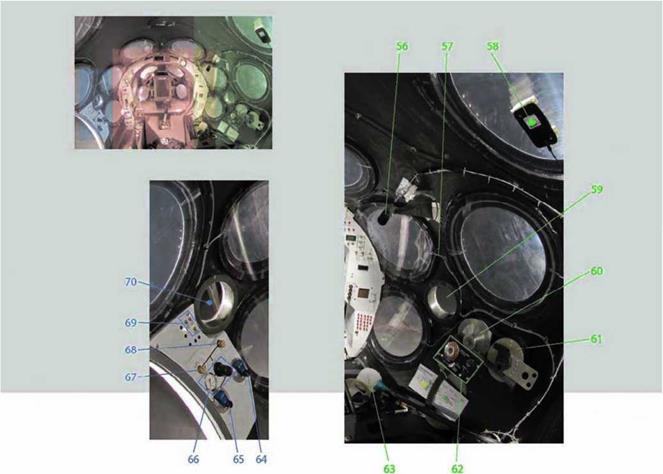
Category Space Ship One

Abort Contingencies (9G)

Melvill continued to expand the flight envelope and to test the feather. Figure 7.12 shows him inside the cockpit pulling the feather control. But he had another important task to complete.

All this flight testing was really aimed at one goal: SpaceShipOne flying a spaceflight. So, every step along the way had to accomplish something that would bring that goal just a little bit closer. But this also meant that contingencies had to be worked out. “Probably the biggest fear we had for every flight was having to abort,” Doug Shane said about the rocket-powered flights.

Scaled Composites had very good confidence in how SpaceShipOne flew by this point. And after an extensive rocket-engine test program on the ground, they also had a good feeling about the rocket engine. So, Scaled Composites felt a safety incident was not likely to result from flying SpaceShipOne or firing the rocket engine. But an abort during a test flight was much more plausible, considering one had already occurred.

If SpaceShipOne aborted while full of fuel and oxidizer, then this would be much too much weight for it to handle during landing. “You

Подпись: г
Подпись: л

Fig. 7.15. The photograph shows Brian Binnie preparing right before his first time flying SpaceShipOne. This would be the last glide flight prior to the start of SpaceShipOne’s rocket – powered test flights. Mojave Aerospace Ventures LLC, photograph by David M. Moore

Подпись:

have to actually dump nitrous to get rid of about 3,000 pounds (1,360 kilograms) of mass. But you couldn’t deal with the rubber in the rocker motor,” Shane said.

For this test flight, Melvill evaluated the emergency handling and landing characteristics. Figure 7.13 shows SpaceShipOne dumping the ballast, which it used to alter the CG during testing. Additional mod­ifications were also made to the landing procedures, and figure 7.14 shows SpaceShipOne’s smooth touchdown.

Propellants

The force that causes a rocket engine’s thrust results from combus­tion. This type of chemical reaction is similar to burning wood. The wood, which is a fuel, and the air, which is an oxidizer, react to form gases and other substances. Both the fuel and oxidizer must be present for combustion to occur.

The difference with a rocket engine is that the fuel and the oxi­dizer release much higher energy, and the gases from the reaction travel out of the nozzle at very high speeds. These high-speed gases provide the thrust.

Each Space Shuttle SRB contains 1,100,000 pounds (500,000 kilograms) of solid propellant, 70 percent ammonium perchlorate for its oxidizer and 16 percent aluminum powder for its fuel. The balance consists of binders, curing agents, and catalysts. These burn until there is nothing left to burn. The liquid propellants are contained in separate pressurized tanks within the ET. These tanks hold 1,350,000 pounds (612,000 kilograms) of liquid oxygen oxidizer, often called LOX, and 227,800 pounds (103,000 kilograms) of liquid hydrogen fuel. The main engines produce thrust when the liquid oxygen and liquid hydrogen are pumped together.

Propellants

Propellants

C >

Fig. 5.3. To reach orbit, the Space Shuttle uses three liquid-fueled rocket engines, the shuttle main engines (SME) at the rear of the orbiter and two solid rocket boosters (SRB), which are attached to the external tank (ET). Dan Linehan

V_________________ )

SpaceShipOne is a tiny fraction of the Space Shuttle’s mass, and it reaches less than a third of the height the Space Shuttles does. So, the propellant requirements are quite different. SpaceShipOne used nitrous oxide (N20), a colorless liquid or gas naturally occurring in the atmosphere. Nitrous oxide is commonly used as laughing gas, as a hot rod fuel additive for a quick boost of speed, and as a propellant for whipped cream. The N20 is liquefied and used as the oxidizer. The oxidizer enables the fuel to burn at a near-explosive rate. The oxidizer tank contains 3,000 pounds (1,360 kilograms) of N20.

г ^

Fig. 5.4. When the oxidizer and the fuel combine, a vigorous chemical

reaction takes place. The very hot gases from this combustion produce the thrust and resulting fiery plume. Mojave Aerospace Ventures LLC, photo provided courtesy of Discovery Channel and Vulcan Productions, Inc.

Hydroxyl-terminated polybutadiene (HTPB) is the solid used for the fuel and is a synthetic rubber, like that used to make tires. About 600 pounds (270 kilograms) fuel the rocket engine. Both the oxidizer and the fuel can easily and safely be stored and transported. In fact, unlike liquid oxygen and liquid hydrogen, which react together spon­taneously, N20 and HTPB will not react together unless an igniter is first used. For the reaction to occur, the temperature must be greater than 570 degrees Fahrenheit.

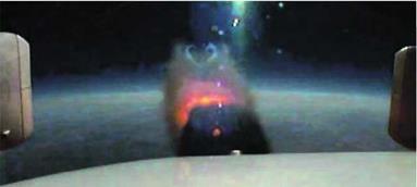
The combustion products from the combination of N20 and HTPB are mostly carbon dioxide, carbon monoxide, hydrogen, nitrogen, and water vapor. This is not as clean burning as the Space Shuttle’s main engines but is much less polluting than the Space Shuttle’s solid rocket boosters, which produce a giant, toxic acid cloud. Figure 5.3 and figure 5.4 show the rocket engines of the Space Shuttle and SpaceShipOne firing, respectively.

Ready for Rocket Power (10G)

The rocket engine had been qualified only a few weeks previously and was ready to make its debut. Test flight 10G would be the last glide flight before attempting to light off the rocket engine with SpaceShipOne. Figure 7. IS shows Brian Binnie readying himself for his first flight in SpaceShipOne, and figure 7.16 shows flight engineer Matt Stinemetze making preparations in White Knight right before takeoff.

r—————————————– ^

Flight Test Log Excerpt for 10G

Date: 4 December 2003

Flight Number Pilot/Flight Engineer

SpaceShipOne 10G Brian Binnie

White Knight 42L Pete Siebold/Matt Stinemetze

Objective: The seventh glide flight of SpaceShipOne and new pilot check out. Full functional check of the propulsion system by cold flowing nitrous oxide. Completed airspeed and positive and negative g-envelope expansion.

(source: Mojave Aerospace Ventures LLC, provided courtesy of Scaled Composites)

V____________________________________ )

Ready for Rocket Power (10G)г ; >

Fig. 7.17. SpaceShipOne was released at a height of 48,400 feet (14,750 meters). This video­capture image shows SpaceShipOne and White Knight mated up just prior to separation. The contrails from White Knight’s turbojet engines can be seen trailing off in the background.

Mojave Aerospace Ventures LLC, video capture provided courtesy of Discovery Channel and Vulcan Productions, Inc.

V_________________________________________________

Ready for Rocket Power (10G)

Brian Binnie would now have a chance behind the control stick of SpaceShipOne. White Knight carried SpaceShipOne to the highest release altitude yet, 48,400 feet (14,750 meters). Figure 7.17 shows a close – up of SpaceShipOne attached to White Knight with the contrails from White Knight’s afterburners streamed away in the background.

A cold run of the rocket was performed. Binnie used all the controls and instruments for the rocket, including flowing the liquid N20 oxidizer
through the CTN (case/throat/nozzle) as if it were an actual rocket burn. However, without igniting the fuel, no combustion occurred.

After the successful cold run, Binnie turned his attention to com­pleting the airspeed and g-force envelope expansion. Binnie pushed SpaceShipOne the hardest so far, and when finished, he glided back to Mojave, as shown in figure 7.18, eager for the next phase of flight testing to begin.

Ready for Rocket Power (10G)

Up to this point, the contrails in the air only came from the twin turbojets on White Knight After a total of ten unpowered flights, some captive carry and some glide, SpaceShipOne was ready to light its hybrid rocket engine for the first time in the sky. Tyson V. Rininger

Construction Begins

Scaled Composites took what it described as an advanced all-composite design approach to building the rocket engine. “We did develop a new configuration of hybrid rocket motor,” Rutan said. “And we patented it. The patent is related to the fact that the whole motor cantilevers off the tank. And doesn’t require additional mounting and doesn’t build up stresses because of the temperature effects and the aerodynamic loads. It’s a key reason that this remains a very simple motor.

“During our development of the new hybrid rocket motor,” Rutan added, “Scaled contracted with four companies to provide components.” Most of the rocket engine was designed and developed in-house, though.

The two main parts of the rocket engine are the oxidizer tank and the integrated case/throat/nozzle (CTN), as shown in figure 5.5 and figure 5.6, respectively.

The oxidizer tank is a very important structural element of the rocket engine and SpaceShipOne as a whole. It is reusable and is bonded to the inside of the fuselage, all the way around, with an elastomeric

Construction Begins

Construction Begins

Construction BeginsГ – ^

Fig. 5.5. This oxidizer tank stored the liquid nitrous oxide (N20). After the tank was filled, it self pressurized, so a pump was not needed to inject the oxidizer into the fuel. The photo shows the inner liner of the oxidizer tank. Mojave Aerospace Ventures LLC, photograph by David M. Moore

compound. The bond is damage tolerant and isolates vibration, and because of the size of the bond area, the loading due to the force from the rocket engine is distributed over a large area.

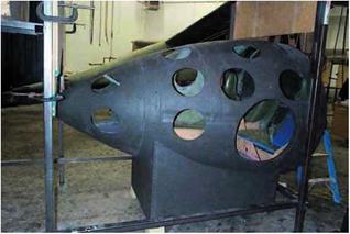
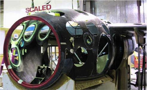
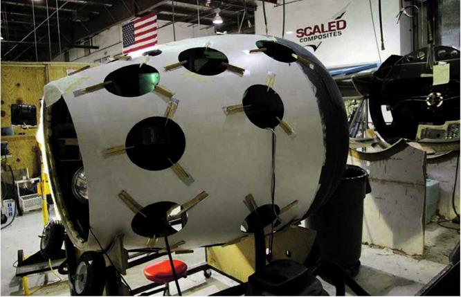
The oxidizer tank has a fiberglass liner and two titanium interface flanges, fore and aft. After pressure testing the liner, Scaled Composites contracted Thiokol to provide a graphite/epoxy overwrap using a filament-wrap process, which can be seen in figure 5.7.

The CTN is mounted directly on the rear flange of the oxidizer tank with bolts and an О-ring seal (refer to figure 5.8).This cantilever mounting requires no other additional support, and, by design, reduces the number of potential leak paths.

( >

Fig. 5.6. The CTN (case/throat/nozzle) was a large composite casing

filled with synthetic rubber used as fuel. Once the rocket engine was ignited, the exhaust moved through the casing, was compressed by the throat, and then expelled out the nozzle. Mojave Aerospace Ventures LLC, photograph by Scaled Composites

V__________________________________________ J

r ; ^

Fig. 5.7. The oxidizer tank had a special composite overwrap that allowed it to contain the oxidizer at a high pressure of 750 pounds per

square inch (psi). It was permanently bonded to the inside of the fuselage, so it was also an important structural member. Mojave Aerospace Ventures LLC, photograph by Scaled Composites

Construction Begins

Construction BeginsПодпись: лг

Fig. 5.8. The CTN attached directly to the oxidizer tank. This photograph shows the mounting ring used to bolt it on. The hybrid design allowed the fuel and oxidizer to be very close together, which reduced the overall complexity of the rocket engine. Mojave Aerospace Ventures LLC, photograph by David M. Moore

V_________________________________________

The 22-inch – (56-centimeter-) diameter case of the CTN, where the combustion occurs, is essentially a hollow tube lined with the rubber fuel. The throat forced the hot exhaust gases, passing from the case to the nozzles, to converge. The nozzle accelerated the hot exhaust gases to provide even greater thrust. The silica/phenolic high-temperature insulating liner and mounting rings of the case were assembled together with the throat and nozzle using graphite/epoxy composite overwrap. The cantilevered mounting also provided the advantage of being able to vary the length and diameter of the CTN without design modifications.

A safety feature was built into the CTN to warn of an impending burn-through. If the fiber-optic cable sealed between the liner and the overwrap detected a breach in the liner, the flow of oxidizer would be cut off and the rocket engine shut down. As an additional precaution, wires wrapped around the outside of the CTN could also be used to detect a burn-through.

AAE Aerospace supplied an ablative nozzle with an expansion ratio of 25:1 for the CTN. The expansion ratio compares the size of the throat to the size of the nozzle’s opening. The efficiency is altitude dependent, so this ratio gave SpaceShipOne the maximum thrust at launch altitude. The interior of the nozzle eroded away as the rocket engine burned, which helped to minimize the temperature of the nozzle itself.

The entire CTN had to be replaced after each spaceflight.

Scaled Composites looked to outside vendors to supply the remaining components for the rocket engine, which included the injector, the igniter, and the related controls and plumbing. Scaled Composites held a competition of its own to build these components.

Rocket-Engine Competition

Simplicity of design by reducing the number of parts is best illus­trated by an experience Rutan had during his preliminary research into rocket-engine designs. Representatives of a rocket – engine vendor Rutan was visiting wanted to demonstrate how

Construction Begins

Г

Fig. 5.9. At the front of the oxidizer tank are the fill, vent, and dump valves. The vent valve protects from over-pressurization, and the dump valve allows the tank to be drained in an emergency situation. Mojave Aerospace Ventures LLC, photograph by David M. Moore

their valve worked after showing him schematics and describing their engine design. They went out to the back of the building, where the valve was chilled with liquid nitrogen to a cryogenic operating temperature.

“The valve stuck,” Rutan said. “It didn’t work. It failed right there while I was looking at it.”

After they went back inside, he said to them, “Gentlemen, let me ask you, how many of those valves are in this motor?”

Twelve, they replied.

“Did you expect this to work today?” he asked.

There was no answer. Rutan knew enough about rocketry to know if there was such a thing as a simple one that operated at room temperature with one valve, that’s the one he wanted.

Rutan had been looking at more than twenty rocket-engine vendors. With the help of Tim Pickens, a bit of a maverick rocket expert, Rutan sketched up the design and passed it on. “I had sent them a sanitized requirement that didn’t divulge that we were doing manned flight. I said it was a reusable sounding rocket.”

Now, it was necessary to build the remaining engine components. In front of the oxidizer tank was the fill, vent, and dump system as well as the forward tank bulkhead. This was how the liquid nitrous oxide was added to the tank, how pressure was relieved in case of over-pressurization, and how the nitrous oxide could be drained in an emergency situation. These components were kept away from the hot side of the oxidizer tank to improve safety. The locations of these components are shown in figure 5.9.

Arguably the most critical valve of the whole project was the main control valve that supplied the oxidizer to the CTN. Without
the flow of nitrous oxide, there would be no rocket. So, this valve received special attention. Doug Shane cleverly named it the “oxy – no-more-on” valve. Connected to the oxy-no-more-on valve was the injector, which was essentially a showerhead that sprayed the liquid nitrous oxide into the CTN. Both the oxy-no-more-on valve and the injector were located inside the oxidizer tank. What this did was further reduce plumbing and had the added benefit of keeping these components at a constant temperature, which also simplified things. Figure 5.10 shows their positions from a rear view of the oxidizer tank.

The rear tank bulkhead, motor controller, head insulation, and igniter still needed to be built as well. The igniter was the heat source that initiated the reaction between the oxidizer and rubber fuel. The last part that remained was the actual rubber fuel itself, which had to be packed into the CTN.

From the list of more than twenty potential rocket-engine vendors, it came down to two: Environmental Aeroscience Corporation (eAc), of Miami, Florida, and SpaceDev, of Poway, California. This wasn’t a low-bid process. It was performance-based, and the competition would go back and forth. Rutan thought that having just one vendor try to make the last of the components was too much of a risk. “When you sole source, if they stumble, you have to pay them to pick up,” Rutan said. “If you’ve got two of them competing and they stumble, they spend their own money to catch up. That’s what the big ‘C’-word is—competition. And that happened. They both wanted to fly.”

In the middle of 2001, both vendors began to participate in a ground-test program that included cold flow tests, where the oxi­dizer and fuel weren’t ignited, as well as partial – and full-duration

Construction Begins

Construction BeginsГ Л

Fig. 5.10. The CTN mounted on a titanium flange at the rear of the oxidizer tank. Located inside the tank was the main control valve, also known as the "oxy-no-more-on" valve, that released the oxidizer into the CTN. Mojave Aerospace Ventures LLC, photograph by David M. Moore

v__________________ J

г

Construction BeginsConstruction BeginsFig. 5.11. The test stand trailer (TST) was used during the rocket – engine test firings. It contained all of the same components and systems to be used in SpaceShipOne, including an oxidizer tank that the CTNs were mounted onto. Mojave Aerospace Ventures LLC, photograph by David M. Moore

Construction Begins

r ; л

Fig. 5.12. To fill SpaceShipOne or the TST with the oxidizer, nitrous oxide (N20), Scaled Composites used a special tanker truck called the mobile nitrous oxide delivery system (MONODS). Mojave Aerospace Ventures LLC, photograph by David M. Moore

V_______ )

hot-firings. All rocket engine testing employed the same type of compo­nents used in SpaceShipOne. Shaking out the full-scale designs on the ground at a Scaled Composites test site rather than in flight was a much more preferable way to address the “ups”—break up, burn up, and blow up.

In terms of experience, eAc had built a lot of hybrid rocket engines and had run some with diameters of up to 16 inches (41 centimeters). SpaceDev, on the other hand, had only run little hybrids with 15 pounds-force (67 newtons) of thrust.

This meant eAc was off to a quick lead. By June of 2002, the first set of results came in. Scaled Composites selected eAc as the supplier of the front-end propulsion components. However, both vendors continued to develop the remaining rocket-engine components.

To run all the rocket-engine tests, the test stand trailer (TST), a partial, operational mockup of SpaceShipOne shown in figure 5.11, acted as a portable test bed. It comprised the complete rocket engine, including the CTN and oxidizer tank, and the forward section of the fuselage. The TST provided instrumentation to analyze vibration, temperature, and stress conditions that the flight components would face during spaceflight. It also had load cells, which were sensors mounted on the trailer, that allowed engineers to evaluate the rocket – engine performance.

Setup for rocket-engine tests typically took several days. Since the TST was mobile, preparations began inside a hangar at Scaled Composites. Once the CTN was in place and all the other com­ponents were hooked up, the TST was towed out to the firing range. Figure 5.12 shows the specialized tanker truck called the mobile nitrous oxide delivery system (MONODS) that then fills the oxidizer tank.

Mission Control ran the rocket-engine tests remotely, and an under­ground computer near the TST collected and transmitted live data. The countdown procedures for the ground testing are listed in table 5.1.

Since testing occurred on the ground, a nozzle with an expansion ratio of 10:1 was used, as opposed to 25:1 used for actual flights.

SpaceDev had fired first, a 15-second burn on November 21, 2002. The rocket roar was deafening for each hot-fire of the rocket engine. The ground shook. Figure 5.13 shows the tip of a fiery plume stretched out more than thirty feet, scorching the ground and sending smoke billowing across the desert.

“The SpaceDev motor was the only one that had a critical safety issue. In the first round, a valve wouldn’t close and it keep burning and burning,” Rutan said. Although Scaled Composites was slow to extinguish the fire, no significant damage occurred.

After more than nine months of firing rocket engines, the gap between eAc and SpaceDev had disappeared. Each had little differences. For example, SpaceDev used four ports to flow the oxidizer into the CTN, whereas eAc used just one, and they each had a proprietary rubber fuel and system for refueling the CTN. But both had exceeded performance expectations.

With the exception of the fire caused by a stuck valve at the very onset of test firing, the hybrid rocket engine demonstrated safety and reliability. The cantilever mounting concept proved structurally sound, the oxidizer and CTN performed as designed, and the “ups” were avoided altogether.

Scaled Composites had both companies commit prices for compo­nents, not only for the upcoming flight test and Ansari X Prize rocket engines, but for twenty-two other rocket engines slated for what was called Task 21, the spaceflights after the Ansari X Prize attempts.

Construction Begins

Table 5.1 Rocket Engine Test Countdown

(source: Mojave Aerospace Ventures LLC, provided courtesy of Scaled Composites)


T-48 hours Mounting the CTN

The fully fueled CTN (engine) and valve are mounted to the oxidizer tank using the mounting trolley. Alignment is checked and bolts are tightened to the specified tolerances.

T-36 hours Instrumentation and Integration

The motor controller, pressure bottles, actuation valves, and all the sensors are installed and tested on the test bed. New CTNs require new temperature and strain sensors, while CTNs being fired for the second or third time are "plug and play."

T-24 hours Moving Time

The test trailer with the fully fueled CTN (engine) is moved from Scaled’s hangar to the test site. There it is bolted down, final instrumentation is completed, and the system is connected to Mission Control.

T-4 hours Filling the Tank

Nitrous oxide is transferred from the MONODS to the oxidizer tank on the test trailer after it has been brought up to temperature and pressure. Temperatures and pressures must be carefully controlled to ensure a safe transfer.

T-0 hours The Final Countdown

After final system checks have been made, cameras have been started, and range safety has been checked, a quick countdown is called and the switch is thrown. The motor controller automatically ignites and fires the engine for a preprogrammed period of time.

“SpaceDev’s components were lighter, which helped our perform­ance,” Rutan said. “Keep in mind, we knew that we had to have really the best performance in order to win the X Prize because we had a weight growth. So, we needed all the performance we could get. SpaceDev’s components had a little more efficiency, on the order of three percent for the same weight of propellant.”

SpaceDev actually turned out to be cheaper, too—all characteristics Rutan was very fond of. In September of 2003, the development phase of SpaceShipOne’ s rocket engine was completed. SpaceDev got the nod.

Figure 5.14 shows a rocket engine installed in SpaceShipOne without the fairing in place, so the unsupported ended of the CTN is apparent.

Rockets Ignite

S

caled Composites revealed SpaceShipOne to the public on April 18, 2003, but it had been running in secret for two years. On November 18, 2003, after about a year-long rocket-engine competition and seven glide flights, the hybrid rocket engine was qualified for flight testing in SpaceShipOne.

Flight testing is risky. Things go wrong as never-before-tested systems are evaluat­ed or new conditions are encountered. It is all part of the process of shaking the design out. It is like an artist making a sculpture of an airplane from a block of wood. At first it doesn’t look like anything, but slowly as pieces of wood are whittled away and form starts to take shape, little by little an airplane becomes more recognizable.

The process of flight testing is pretty much the same as testing other high-performance machines, whether it is a new racing sailboat or a new sports car. Nothing comes off the drawing board perfect. Flight testing is a flying laboratory. And as long as there are many more big steps moving forward than there are moving backward, good progress toward the goal is being made.

Scaled Composites attempted to become the first private company to go to space, yet the company had never even built an aircraft that broke the sound barrier. In fact, no private company had ever built an aircraft that broke the sound barrier as part of a non-governmental program.

The sound barrier, once thought impenetrable and its threshold guarded by demons, was smashed, along with the demons, by Chuck Yeager in the Bell X-l. Although this happened in 1947, the transition from subsonic to transonic to

( >1

Fig. 8.1. On December 17,

Rockets Ignite1903, Orville Wright, flying a

twin pusher-propeller biplane

with a canard, lifted off from

the sandy dunes of Kitty

Hawk, North Carolina. This

was the first flight of a

heavier-than-air, powered

aircraft capable of sustained

and controlled flight. NASA

v___________________ )

Rockets Ignite

supersonic was still a dangerous one. Before SpaceShipOne reached past the boundary of Earth’s atmosphere, it would have to fly faster—several times faster—than the speed of sound.

“The powered flights were very different,” Mike Melvill said. “As a glider, it is completely silent, and there is no noise at all. You don’t have this overload of sensory audio. The audio side of your senses is really overloaded when the rocket motor starts. It’s very, very noisy. It vibrates a lot. It really shakes you around in the airplane. It’s a pretty exciting thing to do. The acceleration is enormous. You drop off the hooks and light the rocket motor. You get this enormous kick in your back. And right away, you turn the corner and point it straight up.”

Flying above Mach 1 was not the same as flying below Mach 1. Flying outside the atmosphere was not the same as flying within the atmosphere. And flying with a rocket engine was not the same as flying without a rocket engine.

Flight testing would now have to be taken up a few notches.

Rocket-Engine Operation

On November 18, 2003, Scaled Composites qualified a rocket engine in preparation for the first powered flight of SpaceShipOne.

“The nice thing about this particular type of hybrid motor is the nitrous oxide is room temperature in the oxidizer tank in front. It self-pressurizes to about 750 pounds per square inch,” Doug Shane
said. This eliminated the need for complicated and expensive pumps to flow the oxidizer into the CTN. In figure 5.15a panel on the belly of SpaceShipOne is removed, exposing the engine bay, so the CTN could be easily mounted.

The oxidizer tank was filled with liquid nitrous oxide through its forward bulkhead. The MONODS pumped the nitrous oxide at 300 pounds per square inch and 0 degrees Fahrenheit. To bring the temperature up to room temperature and maintain it there, engine bleed air from White Knight flowed into SpaceShipOne and was directed at both ends of the tank during captive carry.

The rocket engine of SpaceShipOne could only be fired once. After the rocket engine was armed and the fire switch thrown, the igniter produced a significant amount of heat, causing combustion between the oxidizer and fuel.

“SpaceShipOne does not have a throttle. It is on or off,” Rutan said. “There was no need for a throttle.”

For the spaceflights, the force of thrust was 16,800 pounds-force (74,730 newtons). However, because of performance concerns and

Rocket-Engine Operation

Подпись: ~ J ґ

Fig. 5.13. Scaled Composites was able to monitor the performance of each rocket engine tested during the development phase. Data collected by sensors on the TST was relayed to engineers real-time for analysis. Mojave Aerospace Ventures LLC, photograph by David M. Moore

к_________________________________________________________________________________________

Rocket-Engine Operation

Rocket-Engine Operation

г ; ^

Fig. 5.15. Between each spaceflight, it was necessary to replace the spent CTN with a fully fueled CTN. The spent CTN can be refurbished by refueling the rubber inside the casing and replacing the ablative nozzle. Mojave Aerospace Ventures LLC, photograph by Scaled Composites

( >

Fig. 5.14. This photograph shows the rocket engine before the engine

fairing was attached. The cantilever rocket-engine design patented by Scaled Composites had the CTN fixed to the oxidizer tank at one end but completely unsecured at the nozzle end. Mojave Aerospace Ventures LLC, photograph by Scaled Composites

V__________________________________________ J the additional payload required by the Ansari X Prize competition, additional nitrous oxide oxidizer and rubber fuel were added, as well as an increase in burn duration. The thrust and the specific impulse (I$p), a measure of efficiency of the rocket engine, were not officially released by Scaled Composites.

Peak performance occurred once the rocket engine ignited. As the rubber burned away and the oxidizer tank emptied, the amount of thrust gradually reduced.

About sixty seconds into the burn, the nitrous oxide began a transition from liquid to gas because there was more room in the oxidizer tank for it to expand, which caused a significant decrease in thrust. At this point, the combustion was uneven throughout the CTN and caused SpaceShipOne to chug along for about five seconds. The ride then smoothed out for the remainder of the burn now that the nitrous oxide had transformed to gas.

During the flight, the engine performance and parameters could be monitored in the cockpit by the pilot and on the ground in Mission Control.

Rocket-Engine Operation

Brian Binnie stands in front of SpaceShipOne with its feather extended. In addition to the feather, SpaceShipOne required three other systems for control during a spaceflight: the mechanical flight control system for subsonic speeds, the electric flight control system for supersonic speeds, and the reaction control system (RCS) for space. Mojave Aerospace Ventures LLC, photograph by Scaled Composites


Rocket-Engine Operation

SpaceShipOne Instruments and Controls

paceShipOne is part airplane, missile, spacecraft, and glider. Like the North American X-1S, it was flown by hand. Figure 6.1 shows SpaceShipOne during a glide test flight with its control surfaces clearly visible on the tail booms.

To complete each spaceflight mission, it had to transition between a variety of flight phases, including takeoff, captive carry, boost, coast, feather, glide, approach, and landing. Flying these phases, SpaceShipOne crossed between three distinct flight regimes: subsonic, supersonic, and zero-g. Different flight control systems were required to operate in each regime. A basic mechanical control system was used in subsonic flight, while an electric – powered control system and a reaction control system (RCS) were required in supersonic and zero-g flight, respectively.

SpaceShipOne had a set of instruments and controls for each flight control system that the pilot had to switch between. Figure 6.2 shows Mike Melvill in the cockpit holding the control stick of SpaceShipOne with the nose cone detached.

Subsonic Flight Control

SpaceShipOne essentially flew like a light airplane—some of the time anyway. It had a mechanical flight control system that operated manually, similar to that of a Cessna 172 or Piper Cub. A simple cable-and-rod linkage tied the stick and rudder pedals

Rocket-Engine Operation

Подпись: Г

Rocket-Engine Operation

г ^

Fig. 6.1. SpaceShipOne was the first manned aircraft to use tail booms attached to the wingtips. Unlike almost every other aircraft, the wings had no control surfaces. The pilot maneuvered SpaceShipOne with control surfaces that were all located on the tail booms, an upper and lower rudder at the back of each tail boom, flying or movable horizontal stabilizers, and elevons at the trailing edge of each horizontal stabilizer. Mojave Aerospace Ventures LLC, photograph by Scaled Composites

Fig. 6.2. With the nose cone detached, Mike Melvill gets some practice at the controls of SpaceShipOne as Steve Losey, the crew chief, looks on. SpaceShipOne had room for a pilot up front and two passengers in the back row. Mojave Aerospace Ventures LLC, photograph by David M. Moore

N

to the control surfaces. The connections between the pilot’s controls in the cockpit and the control surfaces are shown in figure 6.3. No hydraulics were used for flight control.

All of the control surfaces were located on the tail booms. An upper and lower rudder were mounted at the end of each tail boom. The rudder pedals in the cockpit moved the upper rudders for control of yaw. Refer to figure 6.4 for SpaceShipOne s flight axes and rotations. Each rudder pedal worked independently and deflected the corresponding upper rudder outward only. By depressing both, the upper rudders acted a little bit like a speed brake.

On the horizontal stabilizer, elevons combined the functions of conventional ailerons on the wings and elevators on the tail. The control

f ‘ ^

Подпись:Подпись:Подпись:Rocket-Engine OperationFig. 6.3. This diagram shows the different control systems and the linkages from the controls in the cockpit to the control surfaces. The reaction control system (RCS) and the landing gear are also shown in this cutaway. Mojave Aerospace Ventures LLC, provided courtesy of Scaled Composites

V________________ )

Подпись: Not# Skid (Aids runway braking extends only, gravity and spring driven, crush damper) components

f >1

Fig. 6.4. Each of the three flight control systems allowed SpaceShipOne to maneuver along the flight axes. Pitch and roll were controlled by the elevons at subsonic speeds and by the movable horizontal stabilizers at supersonic speeds. The upper rudders and lower rudders controlled yaw at subsonic and supersonic speeds, respectively. RCS thrusters mounted on the wings and fuselage controlled pitch, roll, and yaw in space. James Linehan

V__________________________________________ J

Rocket-Engine Operationf Л

Fig. 6.5. At the trailing edge of each horizontal stabilizer was an elevon. When both elevons moved in the same direction, the pitch of SpaceShipOne changed. When moved differentially, roll changed. The photograph shows the poor airflow over a horizontal stabilizer during a stall test, as indicated by the small strings attached to the surface. Mojave Aerospace Ventures LLC, video capture provided courtesy of Discovery Channel and Vulcan Productions, Inc.

V______________________________ J

stick moved the elevons, which allowed the pilot to control pitch and roll of SpaceShipOne. Figure 6.5 shows a horizontal stabilizer during testing after modification.

Breaking the Sound Barrier (11P)

On December 17, a flimsy aircraft that no one thought would fly prepared to launch from sand-swept dunes. This wasn’t the Mojave Desert, though. It was 1903 in Kitty Hawk, North Carolina. The Wright brothers proved that a couple of bicycle makers could accomplish the unbelievable—powered, controlled, and sustained flight. Their famous flight is shown in figure 8.1.

One hundred years later, to the day, Scaled Composites also looked to make the unbelievable believable. SpaceShipOne was ready for its first rocket-powered test flight.

The sound barrier posed the greatest challenge the team had yet to face. The choice of pilots was not a straightforward one. Mike Melvill, the most experienced test pilot with Rutan designs, had already piloted SpaceShipOne seven times. Pete Siebold and Brian Binnie had each only flown SpaceShipOne once. During such a critical junc­ture, the test pilot with the greatest stick tim SpaceShipOne would seem like the most likel candidate. But Binnie was selected. The entire fate of Rutan’s space program now rested in his hands.

Flight Test Log Excerpt for 11P

Date: 17 December 2003

Flight Number Pilot/Flight Engineer

SpaceShipOne 11P Brian Binnie

White Knight 43L Pete Siebold/Cory Bird

Objective: The eighth flight of SpaceShipOne and first powered flight, fifteen-second burn of the rocket motor and supersonic flight. Motor light-off at altitude and inflight engine performance. Vehicle handling qualities through transonics and feather performance from altitude.

One of the most obvious reasons for the selection was Binnie’s experience flying supersonic jets for the U. S. Navy. “I would suspect that certainly was part of the thinking that went into it,” Binnie said. “I was also kind of the anointed test director for the rocket motor. So, I was very familiar with all the ins and outs with the motor and its performance. I was comfortable with its design and robustness and performance, more so than perhaps anybody else. And perhaps I had, right from the first time I saw it fire, this image in my mind of how it would play out when put into a vehicle. I was very motivated to fly that flight.”

Binnie also had flown Roton, a spaceship prototype produced by Rotary Rocket, Inc., that was half rocket and half helicopter. “That vehicle was decidedly scary to fly,” Binnie said. “I flew it three times. I thought, ‘You know, if I have to do this one or two more times, I’m pretty sure I’m going to kill myself.’ I was honestly sort of fearful that I’d climb into this thing and not climb out. I never felt that way with the spaceship. There were certainly things that could go wrong that could cause an accident, but I never felt that the accident was going to be life threatening.”

With Pete Siebold flying White Knight, Cory Bird released SpaceShipOne at 47,900 feet (14,600 meters). Dropping down, Binnie stabilized SpaceShipOne and started to pull the nose up.

“We knew very little about it. It was all about risk. Our standard for success was, literally, if the rocket motor lit off even for just a few seconds and we shut it down, we were going to call that a success,” Binnie said.

How would the rocket engine function? Would SpaceShipOne hold together during the enormous acceleration? What about the messy transonic region? How about the cockpit? Would it shake too much or be too loud to operate the vehicle? How would the untested controls work at supersonic? Would SpaceShipOne climb quickly enough so that an overspeed didn’t rip it to pieces?

“This was the riskiest flight of our whole program, probably times five or ten,” Doug Shane said.

At 44,400 feet (13,530 meters) and flying Mach 0.55, Binnie lit the rocket engine. “It’s a real rush to kind of ride something that powerful. Like I said, it is like a tsunami comes through the cabin. You are just taken away. So, it is very exhilarating,” Binnie said.

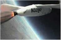
As SpaceShipOne rocketed upward, it broke the sound barrier after only 9 seconds. Figure 8.2 shows SpaceShipOne’s rocket engine firing.

Binnie shut down the rocket engine after a burn duration of 15 seconds as SpaceShipOne hit a maximum speed of Mach 1.2 (800 miles per hour or 1,290 kilometer per hour) while having pulled more than 3 g’s. As SpaceShipOne became the first manned vehicle to have ever used a hybrid rocket engine, it pointed up at 60 degrees and still climbed. SpaceShipOne continued to coast upward and was upside down by the time it reached near-weightlessness at an apogee of 67,800 feet (20,670 meters). Binnie then descended for about a minute with the feather deployed and retracted it at 35,000 feet (10,670 meters).

“It was manageable,” Binnie said. “It wasn’t the most graceful flight. If you looked at it from inside the cockpit, there were a lot of snakes being killed. The boost part of it went extremely well, all things considered, and gave us a lot of confidence that we had a design that was capable. It was only the landing that marred an otherwise wonderful day.”

Breaking the Sound Barrier (11P)

Г ^

Fig. 8.2. Brian Binnie took the controls of SpaceShipOne for test flight number 11P, one hundred years after the flight of the first successful airplane, in which the 1903 Wright Flyer had flown for 12 seconds. Even though Binnie burned the rocket engine for only 15 seconds,

SpaceShipOne broke the sound barrier after only 9 seconds. Mojave Aerospace Ventures LLC, video capture provided courtesy of Discovery Channel and Vulcan Productions, Inc.

ч___________________ ;______________________ J

Breaking the Sound Barrier (11P)

c ^

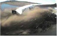
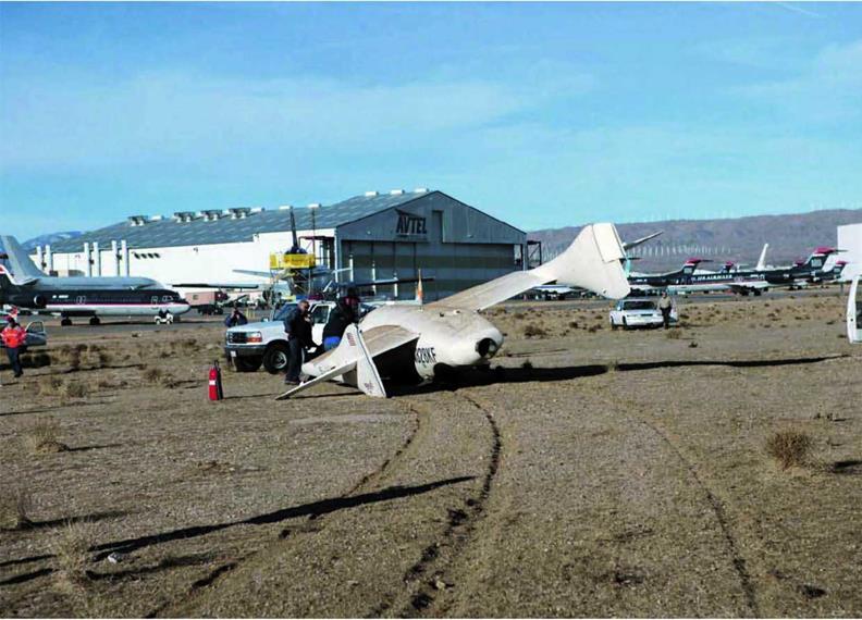
Fig. 8.3. A crash landing blemished an otherwise successful first rocket – powered test flight. SpaceShipOne touched down harder than the landing gear could handle, causing the left rear main landing gear to collapse and SpaceShipOne to skid off the runway. Mojave Aerospace Ventures LLC, video capture provided courtesy of Discovery Channel and Vulcan Productions, Inc.

v__________________________________________ J

On the landing, which had proved to be a surprising and persist­ent source of trouble for Scaled Composites, SpaceShipOne hit very hard. The left main landing gear collapsed, and SpaceShipOne skidded to the left and off the runway into the dirt, as shown in figure 8.3 and figure 8.4.

Burt Rutan gave some clarification about the cause of the crash landing during a press conference late in 2004. He said, “We were testing at that time, a flight control modification that would give us a better margin on flutter in the transonic area. And that damper in the flight controls had gotten so cold that the controls were extremely sticky. That landing wasn’t Brian’s fault. It was the fault of us not doing the proper thing, and that is put­ting a heater on the damper so that it didn’t freeze up on him on the landing approach.”
Breaking the Sound Barrier (11P)
As Binnie was flaring up for the landing, the damper unfroze. The controls buffeted like SpaceShipOne was going to stall. It was actually just the control linkages responding differently, but there was no way that Binnie could have known this. So, he dropped the nose to prevent the stall that he thought was about to occur. As a result, SpaceShipOne came in too fast and too hard for the fragile landing gear.

Supersonic Flight Control

Similar to the Bell X-l, as shown in figure 6.6, which in 1947 was the first aircraft to break the sound barrier, SpaceShipOne used elec­tric, motor-driven control surfaces to maneuver. After SpaceShipOne
broke the speed of sound during test flights, the subsonic flight con­trols no longer functioned efficiently.

“Once you are supersonic, the control system that you normally use to fly the airplane doesn’t work anymore,” Melvill said. “Because it is a mechanically controlled airplane, there is no hydraulic system like there is on an F-16 or F-l 8. It is just cables and pushrods. You are just not strong enough to move the controls at that point. So you just revert to using the trim switches.”

Supersonic Flight ControlГ"

Подпись:Fig. 6.6. Because the forces pushing against the control surfaces of the X-1 were so strong while flying at supersonic speeds, the pilot could not use conventional mechanically linked flight controls. The control surfaces had to be electrically controlled and moved using electric motors. SpaceShipOne used a similar system for flying above Mach 1. NASA-Dryden Flight Research Center

V________________ J

Many aircraft have trim controls that help the pilots maintain course by slightly altering control surfaces. By changing a trim setting, a pilot can fine-tune the control surfaces, so less force has to be applied to the control stick and rudder pedals in order to stay on course. SpaceShipOne uses trim controls in a somewhat similar way during supersonic flight.

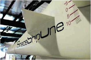
A switch on the top of the control stick activated electric servos that pivoted the entire horizontal stabilizer on each side of SpaceShipOne for pitch trim. In figure 6.7, a close-up of a tail boom shows the numeric scale that indicates the amount of deflection for the horizontal stabilizer as set by the pilot.

Supersonic Flight Control

r ; ^

Fig. 6.7. Triangular strakes were added in front of the horizontal stabilizers, which were also enlarged, to improve the aerodynamics of SpaceShipOne. The numbers to the right of the strake show the amount of trim or deflection of moveable horizontal stabilizers. Mojave Aerospace Ventures LLC, photograph by David M. Moore

V__________________ J

A knob at the pilot’s left side called the “turtle” activated the lower half of each rudder, giving yaw trim. “Yawing the airplane caused it to roll because of the high wing and the swept leading edges,” Melvill said. “We actually didn’t use the roll trim. It was too powerful. We used yaw trim to roll the plane. If it was rolling off to the left, you would yaw it to the right.”

The lower rudders were synced and moved in the same direction, unlike the upper rudders used in subsonic flight. “The geometry is such that they go out a lot and in just a little bit,” Rutan added. “But they never work opposite.”

Trimming was also used to restrict the movement of SpaceShipOne during test flights. For example, when Mission Control monitored the trajectory of SpaceShipOne, they would instruct the pilot to make trim changes in order to help him stay on course.

More than midway through the burn, the atmosphere became so thin that the supersonic flight controls were no longer needed. The pilot was able to control SpaceShipOne with subsonic flight controls, even though it was flying much faster than the speed of sound, because the rarified air produced little opposing force. When SpaceShipOne fully left the atmosphere, the pilot then switched over to the RCS.

Unplugged (12G)

After a little less than three months, SpaceShipOne was ready to return to the air again, with Pete Siebold at the controls. However, its rocket engine would be quiet during this test flight.

“It was after the famous 11P flight, which resulted in significant damage to the aircraft on the hard landing,” Siebold recalled. “It was

Unplugged (12G)Unplugged (12G)in one respect what we would call a functional check flight after any major modifications to the airplane. We wanted to go fly it in a semi – benign environment and try and shake down any of the problems that we may have overlooked or additional problems that had been created due to the modifications.

“The other reason was we made some modifications to the aero­dynamic shape. We added the thermal protection to the aircraft. If you look at the artwork of that flight, it shows the red leading edges and shows the TPS addition. That actually changed the wing shape slightly and the aerodynamic shape. So, we wanted to go and fly that and see if there were any ill effects to that modification for the flight.”

Siebold started off his second time flying SpaceShipOne at an altitude of 48,500 feet (14,780 meters), which was the highest point that White Knight ever released SpaceShipOne. Scaled Composites had originally planned on releasing SpaceShipOne from an altitude of 50,000 feet (15,240 meters). However, White Knight had a very difficult time flying this high and too frequently had come out of afterburners or flamed out altogether at an altitude even below this one. The lower launch altitude did actually work in SpaceShipOne’s favor.

During powered flight, the first thing that SpaceShipOne had to do was “turn the corner” as soon as it possibly could, but the higher the altitude, the less air there was for the wings to bite into in order to make a quick turn upward. So, in terms of utilizing the energy from the rocket engine as efficiently as possible, launching below 48,000 (14,630 meters) feet gave better overall performance, since SpaceShipOne would spend more time pointing up than over.

However, since Siebold wasn’t concerned with lighting off the rocket, he wanted all the altitude he could get for the glide flight. “There were some minor glitches,” he said. “The thermal protection system started cracking at low temperatures, and I think there was actually a formulation change made between that flight and the actual powered flight.”

But the thermal protection system (TPS) wasn’t the only system being checked out. Siebold also evaluated the reaction control system (RCS) that would be used to maneuver SpaceShipOne while in the absence of the atmosphere. This and other testing worked out smoothly, and SpaceShipOne touched down safely, even in the presence of a strong crosswind.

Reaction Control System

Because there is no atmosphere in space, the flight control systems that ordinarily allow an aircraft to move through the air do not work for spacecraft moving through space. Rudders, elevators, and ailerons only work because air moves over them. With no air, they are useless.

In order to maneuver in space, spacecraft take advantage of a simple physics law discovered by Sir Isaac Newton:for every action, there is an equal and opposite reaction.

Without considering a spacesuit, for example, if a person was in space and blew through a straw, the air would move out the straw in one direction and the person would move in the opposite direction.

Figure 6.8 shows an astronaut with a hand-held reaction control system (RCS). To move, he just points the opposite direction, releases a puff of gas, and off he goes in the direction he wants. This, by the way, is the same principle by which a rocket engine works. The RCS thrusters are just miniature rocket engines.

Reaction Control System( ■ >1 Fig. 6.8. In Gemini 4, astronaut Ed White made the first U. S.
spacewalk. To maneuver during his 23-minute extravehicular activity

(EVA), he used a hand-held self maneuvering unit (HHSMU) that shot

little bursts of gas, which allowed him to move around. This device

worked similar to the way SpaceShipOne’s reaction control system works.

NASA-Johnson Space Center

к_________________________ J

The Space Shuttle uses a fuel of monomethylhydrazine (MMH) and an oxidizer of nitrogen tetroxide (N204) for its RCS. These pro­pellants react together spontaneously once in contact. As long as each chemical is stored safely separate, they provide the orbiter a simple, reliable, precise, and powerful RCS.

SpaceShipOne had limited time in space and was much less massive than the Space Shuttle. The force generated by these expensive and toxic chemicals was not required. So, puffs of air were sufficient to maneuver SpaceShipOne in space.

After the aerodynamic control authority was gone, the pilot used the RCS to help slow down or null any rotation that had developed while exiting the atmosphere. Each wingtip had roll thrusters, and along the top, bottom, and sides of the fuselage were pitch and yaw thrusters. Each of these thrusters was essentially a port from which high-pressure air could be expelled, and each thruster had a backup. Redundant 6,000-psi bottles of air powered the RCS. By fully extend­ing the rudder petals and the control stick, the pilot maneuvered SpaceShipOne by triggering microswitches that turned the appropriate thrusters either full-on or full-off.

The RCS was also used to get into position for reentry. Scaled Composites had confidence that the feather would self-right SpaceShipOne. However, they did not want to start off upside-down if they didn’t have to.

Tier One Navigation Unit

The pilot had to fly a specific trajectory carefully during a mission. If he deviated, he risked not only failing to reach the target altitude but also missing the prescribed reentry area or, in the extreme case, being too far away from the landing site.

“The aircraft itself was completely manually controlled,” Pete Siebold said. “So, the only feedback the pilot had to how the airplane was flying was through the avionics system.”

It was necessary to develop an avionics system, called the Tier One navigation unit (TONU), for SpaceShipOne. “There really was nothing available within our budget and nothing available off the shelf that suited our needs. So, we had to go develop it ourselves,” Siebold said. The system navigation unit (SNU) and the flight director display (FDD) were the two primary components that made up the TONU.

“We had contracted a company to basically develop the hardware portion of the nav system,” Siebold said. “They built the boxes and put the computers in. They were initially responsible for developing the software of the navigation system as well. However, we ended up making major modifications to that software at the end of the program to make it perform the way we needed it to perform. On the display side, we wrote all the software for the entire program from the beginning.” Aside from being a test pilot, Siebold was the engineer behind most of the software design. Fundamental Technology Systems (FTS), also an Ansari X Prize competitor, provided the hardware and initial software to Scaled Composites.

Acting as the brain of the TONU, the SNU incorporated both a global positioning system (GPS) and an inertial navigation system (INS). It sent guidance and navigational information to the pilot, who saw it on the liquid crystal display (LCD) screen of the FDD in glass- cockpit-type fashion. The SNU navigates along the primary flight axes in six degrees of freedom: the translations of left/right, forward/back, and up/down and the rotations of yaw, roll, and pitch.

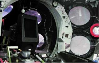
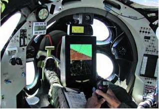
Close-ups of the FDD are shown in figure 6.9 and figure 6.10, which also show the similarity between the cockpits of SpaceShipOne and White Knight.

Fly-by-wire was not an option. Siebold said, “It wasn’t warranted for the complexity of this program. Fly-by-wire adds a whole order of magnitude to the whole vehicle development costs. And we really wanted to keep this as simple as possible in order to make this affordable for everybody. That is really the backbone of this program. If you can make it as simple as a Volkswagen, then everybody can afford it. If it needs to be as complex as the Space Shuttle, then nobody can afford it. We really had to push really hard toward making it affordable from the onset.”

The data available to the pilot is based on several modes that correspond to the different phases of flight for SpaceShipOne. Figures 6.11 to 6.14 show various FDD modes, including a boost, a reentry, and a glide. In these modes, the pilot is given trajectory guidance with respect to a detailed map that tracks the position of SpaceShipOne. The FDD automatically stepped through the different modes while flying the mission, but a control allowed the pilot to manually move through the modes in the unlikely event he needed to do so.

Siebold said, “We had the initial boost portion. So, that was the pull up. Then it transitioned to a pseudo-boost mode were every­thing zoomed in and allowed you to track your final target, fly that

Reaction Control System

г ; л

Fig. 6.9. A close-up of the flight director display (FDD) for SpaceShipOne is shown in this photograph. The FDD was part of the Tier One navigation unit (TONU) and provided the test pilot with instruments similar to the way a glass cockpit does for an airliner.

Mojave Aerospace Ventures LLC, photograph by David M. Moore

V_____________________________________ J apple onto your target. Once the motor shut down, it transitioned to a coast phase. Once you left the atmosphere, it transitioned into a reentry phase. Once you reentered, it transitioned into three different glide phases. We called them high key, final, and landing phase. And those three phases helped you to find your way back to the airport, and manage your energy so that you’d end up touching down at the place you wanted.”

Sometimes SpaceShipOne nearly pointed straight up, and sometimes it was upside-down. The attitude, or orientation, of SpaceShipOne in flight was key flight information provided on the FDD. “It showed you whether or not you are at wings level,” Siebold explained. “One unique aspect of the display was that as you pitched the nose up, when the horizon on the display disappeared, it still gave you situa­tional feedback to tell you what attitude the aircraft was in.”

A second key piece of flight information was the velocity vector. “What that tells you,” Siebold said, “is the direction in which you are currently flying—the direction in which your velocity is currently heading. That was depicted on the screen with what we called the green apple. It was a green circle with a tail and two wings pointing out of it.” So, with the pilot knowing how SpaceShipOne was oriented and how it was moving in flight, the FDD offered two other bits of crucial flight information. These were the location of the optimum trajectory, represented by the “red donut,” and where SpaceShipOne was with respect to it, which was the “green apple.”

In a presentation at NASA Ames, Doug Shane had given the follow­ing succinct description: “The goal is to take that green velocity vector and put it right over that red donut, because that is the flight-director cue. And that gets you to the reentry point that you want. Very simplemindedly, your task is only to get those two circles closed up as quickly as you can. And that establishes essentially a vertical trajectory and gives you the best performance that you can get.”

In addition, the SNU monitored and recorded how the systems of SpaceShipOne were performing and fed this information to the FDD, where it was displayed. “It acted as a caution/warning/advisory system,” Siebold said. “It told you if there is any parameter out of limits, or if

Reaction Control System

Ґ ^

Fig. 6.10. The inside of White Knight’s cockpit, shown here, is remarkably similar to the cockpit of SpaceShipOne. Even the instrumentation and controls are nearly identical, with the obvious exception that SpaceShipOne has rocket-engine controls and White Knight has jet-engine controls. Since White Knight started flying about a year before SpaceShipOne, this allowed Scaled Composites to build up confidence in the instruments prior to flying SpaceShipOne. Also, White Knight could be used as a trainer for SpaceShipOne. Mojave Aerospace Ventures LLC, photograph by Scaled Composites

v___________________ J

there is anything out of limits that would cause you to abort the flight. We had a small list of parameters that if they ever exceeded some allowable range, they’d flash a big red sign that said ‘abort.’”

During the rocket engine burn, things happened fast. There was not a lot of time to make decisions. The TONU did not automatically control SpaceShipOne. “The pilot still had to look at the information, digest it, and make the appropriate decision with that information,” Siebold said.

Data that the SNU collected then displayed to the pilot on the FDD was also transmitted real-time to Mission Control on the ground by a radio frequency (RF) telemetry downlink. In Mission Control, the data reduction system (DRS) collected, processed, and stored all the trans­mitted data and made it accessible to everyone in Mission Control.