Rocket-Engine Operation
On November 18, 2003, Scaled Composites qualified a rocket engine in preparation for the first powered flight of SpaceShipOne.
“The nice thing about this particular type of hybrid motor is the nitrous oxide is room temperature in the oxidizer tank in front. It self-pressurizes to about 750 pounds per square inch,” Doug Shane
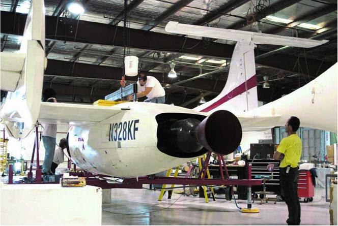
said. This eliminated the need for complicated and expensive pumps to flow the oxidizer into the CTN. In figure 5.15a panel on the belly of SpaceShipOne is removed, exposing the engine bay, so the CTN could be easily mounted.
The oxidizer tank was filled with liquid nitrous oxide through its forward bulkhead. The MONODS pumped the nitrous oxide at 300 pounds per square inch and 0 degrees Fahrenheit. To bring the temperature up to room temperature and maintain it there, engine bleed air from White Knight flowed into SpaceShipOne and was directed at both ends of the tank during captive carry.
The rocket engine of SpaceShipOne could only be fired once. After the rocket engine was armed and the fire switch thrown, the igniter produced a significant amount of heat, causing combustion between the oxidizer and fuel.
“SpaceShipOne does not have a throttle. It is on or off,” Rutan said. “There was no need for a throttle.”
For the spaceflights, the force of thrust was 16,800 pounds-force (74,730 newtons). However, because of performance concerns and

 ґ
ґ
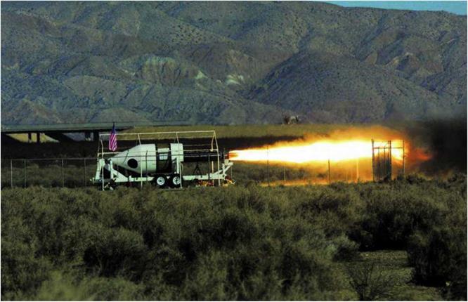
Fig. 5.13. Scaled Composites was able to monitor the performance of each rocket engine tested during the development phase. Data collected by sensors on the TST was relayed to engineers real-time for analysis. Mojave Aerospace Ventures LLC, photograph by David M. Moore
к_________________________________________________________________________________________


г ; ^
Fig. 5.15. Between each spaceflight, it was necessary to replace the spent CTN with a fully fueled CTN. The spent CTN can be refurbished by refueling the rubber inside the casing and replacing the ablative nozzle. Mojave Aerospace Ventures LLC, photograph by Scaled Composites
( >
Fig. 5.14. This photograph shows the rocket engine before the engine
fairing was attached. The cantilever rocket-engine design patented by Scaled Composites had the CTN fixed to the oxidizer tank at one end but completely unsecured at the nozzle end. Mojave Aerospace Ventures LLC, photograph by Scaled Composites
V__________________________________________ J the additional payload required by the Ansari X Prize competition, additional nitrous oxide oxidizer and rubber fuel were added, as well as an increase in burn duration. The thrust and the specific impulse (I$p), a measure of efficiency of the rocket engine, were not officially released by Scaled Composites.
Peak performance occurred once the rocket engine ignited. As the rubber burned away and the oxidizer tank emptied, the amount of thrust gradually reduced.
About sixty seconds into the burn, the nitrous oxide began a transition from liquid to gas because there was more room in the oxidizer tank for it to expand, which caused a significant decrease in thrust. At this point, the combustion was uneven throughout the CTN and caused SpaceShipOne to chug along for about five seconds. The ride then smoothed out for the remainder of the burn now that the nitrous oxide had transformed to gas.
During the flight, the engine performance and parameters could be monitored in the cockpit by the pilot and on the ground in Mission Control.

|

SpaceShipOne Instruments and Controls
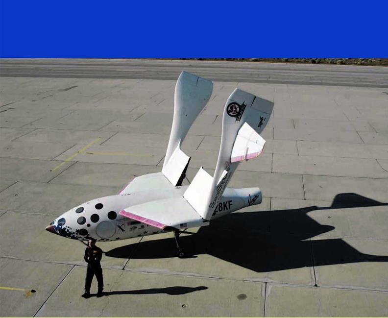
paceShipOne is part airplane, missile, spacecraft, and glider. Like the North American X-1S, it was flown by hand. Figure 6.1 shows SpaceShipOne during a glide test flight with its control surfaces clearly visible on the tail booms.
To complete each spaceflight mission, it had to transition between a variety of flight phases, including takeoff, captive carry, boost, coast, feather, glide, approach, and landing. Flying these phases, SpaceShipOne crossed between three distinct flight regimes: subsonic, supersonic, and zero-g. Different flight control systems were required to operate in each regime. A basic mechanical control system was used in subsonic flight, while an electric – powered control system and a reaction control system (RCS) were required in supersonic and zero-g flight, respectively.
SpaceShipOne had a set of instruments and controls for each flight control system that the pilot had to switch between. Figure 6.2 shows Mike Melvill in the cockpit holding the control stick of SpaceShipOne with the nose cone detached.
Subsonic Flight Control
SpaceShipOne essentially flew like a light airplane—some of the time anyway. It had a mechanical flight control system that operated manually, similar to that of a Cessna 172 or Piper Cub. A simple cable-and-rod linkage tied the stick and rudder pedals


г ^
Fig. 6.1. SpaceShipOne was the first manned aircraft to use tail booms attached to the wingtips. Unlike almost every other aircraft, the wings had no control surfaces. The pilot maneuvered SpaceShipOne with control surfaces that were all located on the tail booms, an upper and lower rudder at the back of each tail boom, flying or movable horizontal stabilizers, and elevons at the trailing edge of each horizontal stabilizer. Mojave Aerospace Ventures LLC, photograph by Scaled Composites
Fig. 6.2. With the nose cone detached, Mike Melvill gets some practice at the controls of SpaceShipOne as Steve Losey, the crew chief, looks on. SpaceShipOne had room for a pilot up front and two passengers in the back row. Mojave Aerospace Ventures LLC, photograph by David M. Moore
N
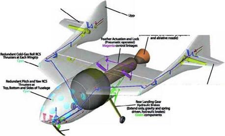
to the control surfaces. The connections between the pilot’s controls in the cockpit and the control surfaces are shown in figure 6.3. No hydraulics were used for flight control.
All of the control surfaces were located on the tail booms. An upper and lower rudder were mounted at the end of each tail boom. The rudder pedals in the cockpit moved the upper rudders for control of yaw. Refer to figure 6.4 for SpaceShipOne s flight axes and rotations. Each rudder pedal worked independently and deflected the corresponding upper rudder outward only. By depressing both, the upper rudders acted a little bit like a speed brake.
On the horizontal stabilizer, elevons combined the functions of conventional ailerons on the wings and elevators on the tail. The control
f ‘ ^
![]()
![]()
![]()
 Fig. 6.3. This diagram shows the different control systems and the linkages from the controls in the cockpit to the control surfaces. The reaction control system (RCS) and the landing gear are also shown in this cutaway. Mojave Aerospace Ventures LLC, provided courtesy of Scaled Composites
V________________ )

f >1
Fig. 6.4. Each of the three flight control systems allowed SpaceShipOne to maneuver along the flight axes. Pitch and roll were controlled by the elevons at subsonic speeds and by the movable horizontal stabilizers at supersonic speeds. The upper rudders and lower rudders controlled yaw at subsonic and supersonic speeds, respectively. RCS thrusters mounted on the wings and fuselage controlled pitch, roll, and yaw in space. James Linehan
V__________________________________________ J
 f Л
f Л
Fig. 6.5. At the trailing edge of each horizontal stabilizer was an elevon. When both elevons moved in the same direction, the pitch of SpaceShipOne changed. When moved differentially, roll changed. The photograph shows the poor airflow over a horizontal stabilizer during a stall test, as indicated by the small strings attached to the surface. Mojave Aerospace Ventures LLC, video capture provided courtesy of Discovery Channel and Vulcan Productions, Inc.
V______________________________ J
stick moved the elevons, which allowed the pilot to control pitch and roll of SpaceShipOne. Figure 6.5 shows a horizontal stabilizer during testing after modification.


