Category NASA’S CONTRIBUTIONS TO AERONAUTICS

Taming Microburst: NASA’s Wind Shear Research Effort Takes Wing

The Dallas crash profoundly accelerated NASA and FAA wind shear research efforts. Two weeks after the accident, responding to calls from concerned constituents, Representative George Brown of California requested a NASA presentation on wind shear and subsequently made a fact-finding visit to the Langley Research Center. Dr. Jeremiah F. Creedon, head of the Langley Flight Systems Directorate, briefed the Congressman on the wind shear problem and potential technologies that might allevi­ate it. Creedon informed Brown that Langley researchers were running a series of modest microburst and wind shear modeling projects, and that an FAA manager, George "Cliff” Hay, and NASA Langley research engineer Roland L. Bowles had a plan underway for a comprehensive airborne wind shear detection research program. During the briefing, Brown asked how much money it would take; Creedon estimated several million dollars. Brown remarked the amount was "nothing”; Creedon
replied tellingly, "It’s a lot of money if you don’t have it.” As the Brown party left the briefing, one of his aides confided to a Langley manager "NASA [has] just gotten itself a wind shear program.” The combination of media attention, public concern, and congressional interest triggered the development of "a substantial, coordinated interagency research effort to address the wind shear problem.”[64]

Taming Microburst: NASA's Wind Shear Research Effort Takes WingOn July 24, 1986, NASA and the FAA mandated the National Integrated Windshear Plan, an umbrella project overseeing several initiatives at different agencies.[65] The joint effort responded both to congressional directives and National Transportation Safety Board recommendations after documentation of the numerous recent wind shear accidents. NASA Langley Research Center’s Roland L. Bowles subsequently oversaw a rigorous plan of wind shear research called the Airborne Wind Shear Detection and Avoidance Program (AWDAP), which included the development of onboard sensors and pilot train­ing. Building upon earlier supercomputer modeling studies by Michael L. Kaplan, Fred H. Proctor, and others, NASA researchers devel­oped the Terminal Area Simulation System (TASS), which took into con­sideration a variety of storm parameters and characteristics, enabling numerical simulation of microburst formation. Out of this came data that the FAA was able to use to build standards for the certifica­tion of airborne wind shear sensors. As well, the FAA created a flight

safety program that supported NASA development of wind shear detection technologies.[66]

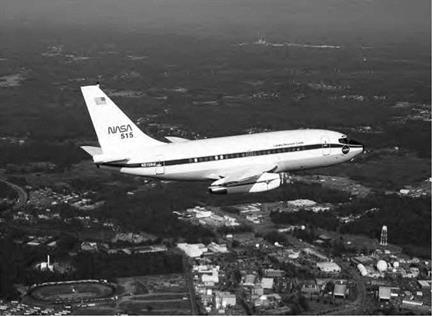
Taming Microburst: NASA's Wind Shear Research Effort Takes WingAt NASA Langley, the comprehensive wind shear studies started with laboratory analysis and continued into simulation and flight eval­uation. Some of the sensor systems that Langley tested work better in rain, while others performed more successfully in dry conditions.[67] Most were tested using Langley’s modified Boeing 737 systems testbed.[68] This research airplane studied not only microburst and wind shear with the Airborne Windshear Research Program, but also tested electronic and computerized control displays ("glass cockpits” and Synthetic Vision Systems) in development, microwave landing systems in development, and Global Positioning System (GPS) navigation.[69]

NASA’s Airborne Windshear Research Program did not completely resolve the problem of wind shear, but "its investigation of microburst detection systems helped lead to the development of onboard monitor­ing systems that offered airliners another way to avoid potentially lethal situations.”[70] The program achieved much and gave confidence to those pursuing practical applications. The program had three major goals. The first was to find a way to characterize the wind shear threat in a way that would indicate the hazard level that threatened aircraft. The second was to develop airborne remote-sensor technology to provide accurate, forward­looking wind shear detection. The third was to design flight management systems and concepts to transfer this information to pilots in such a way that they could effectively respond to a wind shear threat. The program had to pursue these goals under tight time constraints.[71] Time was of the essence, partly because the public had demanded a solution to the scourge of microburst wind shear and because a proposed FAA regulation stipu­lated that any "forward-looking” (predictive) wind shear detection tech­nology produced by NASA be swiftly transferred to the airlines.

An airborne technology giving pilots advanced warning of wind shear would allow them the time to increase engine power, "clean up”
the aircraft aerodynamically, increase penetration speed, and level the airplane before entering a microburst, so that the pilot would have more energy, altitude, and speed to work with or to maneuver around the microburst completely. But many doubted that a system incorporating all of these concepts could be perfected. The technologies offering most potential were microwave Doppler radar, Doppler Light Detecting and Ranging (LIDAR, a laser-based system), and passive infrared radiome – try systems. However, all these forward-looking technologies were chal­lenging. Consequently, developing and exploiting them took a minimum of several years. At Langley, versions of the different detection systems were "flown” as simulations against computer models, which re-created past wind shear accidents. However, computer simulations could only go so far; the new sensors had to be tested in actual wind shear condi­tions. Accordingly, the FAA and NASA expanded their 1986 memoran­dum of understanding in May 1990 to support flight research evaluating the efficacy of the advanced wind shear detection systems integrating airborne and ground-based wind shear measurement methodologies. Researchers swiftly discovered that pilots needed as much as 20 sec­onds of advance warning if they were to avert or survive an encounter with microburst wind shear.[72]

Taming Microburst: NASA's Wind Shear Research Effort Takes WingKey to developing a practical warning system was deriving a suit­able means of assessing the level of threat that pilots would face, because this would influence the necessary course of action to avoid potential disaster. Fortunately, NASA Project Manager Roland Bowles devised a hazard index called the "F-Factor.” The F-Factor, as ultimately refined by Bowles and his colleagues Michael Lewis and David Hinton, indi­cated how much specific excess thrust an airplane would require to fly through wind shear without losing altitude or airspeed.[73] For instance, a typical twin-engine jet transport plane might have engines capable

of producing 0.17 excess thrust on the F-Factor scale. If a microburst wind shear registered higher than 0.17, the airplane would not be able to fly through it without losing airspeed or altitude. The F-Factor pro­vided a way for information from any kind of sensor to reach the pilot in an easily recognizable form. The technology also had to locate the position and track the movement of dangerous air masses and provide information on the wind shear’s proximity and volume.[74] Doppler-based wind shear sensors could only measure the first term in the F-Factor equation (the rate of change of horizontal wind). This limitation could result in underestimation of the hazard. Luckily, there were several ways to measure changes in vertical wind from radial wind measurements, using equations and algorithms that were computerized. Although error ranges in the device’s measurement of the F-Factor could not be elim­inated, these were taken into account when producing the airborne system.[75] The Bowles team derivation and refinement of the F-Factor constituted a major element of NASA’s wind shear research, to some, "the key contribution of NASA in the taming of the wind-shear threat.” The FAA recognized its significance by incorporating F-Factor in its regulations, directing that at F-Factors of 0.13 or greater, wind shear warnings must be issued.[76]

Taming Microburst: NASA's Wind Shear Research Effort Takes WingIn 1988, NASA and researchers from Clemson University worked on new ways to eliminate clutter (or data not related to wind shear) from information received via Doppler and other kinds of radar used on an airborne platform. Such methods, including antenna steering and adap­tive filtering, were somewhat different from those used to eliminate clut­ter from information received on a ground-based platform. This was

because the airborne environment had unique problems, such as large clutter-to-signal ratios, ever-changing range requirements, and lack of repeatability.[77]

Taming Microburst: NASA's Wind Shear Research Effort Takes WingThe accidents of the 1970s and 1980s stimulated research on a vari­ety of wind shear predictive technologies and methodologies. Langley’s success in pursuing both enabled the FAA to decree in 1988 that all commercial airline carriers were required to install wind shear detec­tion devices by the end of 1993. Most airlines decided to go with reactive systems, which detect the presence of wind shear once the plane has already flown into it. For American, Northwest, and Continental— three airlines already testing predictive systems capable of detecting wind shear before an aircraft flew into it—the FAA extended its deadline to 1995, to permit refinement and certification of these more demand­ing and potentially more valuable sensors.[78]

From 1990 onwards, NASA wind shear researchers were partic­ularly energetic, publishing and presenting widely, and distributing technical papers throughout the aerospace community. Working with the FAA, they organized and sponsored well-attended wind shear con­ferences that drew together other researchers, aviation administrators, and—very importantly—airline pilots and air traffic controllers. Finally, cognizant of the pressing need to transfer the science and technology of wind shear research out of the laboratory and onto the flight line, NASA and the FAA invited potential manufacturers to work with the agencies in pursuing wind shear detector development.[79]

The invitations were welcomed by industry. Three important avionics manufacturers—Allied Signal, Westinghouse, and Rockwell Collins—sent engineering teams to Langley. These teams followed NASA’s wind shear effort closely, using the Agency’s wind shear simulations to enhance the capabilities of their various systems. In 1990, Lockheed introduced its Coherent LIDAR Airborne Shear Sensor (CLASS), developed under con­tract to NASA Langley. CLASS was a predictive system allowing pilots to avoid hazards of low-altitude wind shear under all weather conditions. CLASS would detect thunderstorm downburst early in its development
and emphasize avoidance rather than recovery. After consultation with airline and military pilots, Lockheed engineers decided that the system should have a 2- to 4-kilometer range and should provide a warning time of 20 to 40 seconds. A secondary purpose of the system would be to provide predictive warnings of clear air turbulence. In conjunction with NASA, Lockheed conducted a 1-year flight evaluation program on Langley’s 737 during the following year to measure line-of-sight wind velocities from many wind fields, evaluating this against data obtained via air – and ground-based radars and accelerometer-based systems and thus acquiring a comparative database.[80]

Taming Microburst: NASA's Wind Shear Research Effort Takes WingAlso in 1990, using technologies developed by NASA, Turbulence Prediction Systems of Boulder, CO, successfully tested its Advance Warning Airborne System (AWAS) on a modified Cessna Citation small, twin-jet research aircraft operated by the University of North Dakota. Technicians loaded AWAS into the luggage compartment in front of the pilot. Pilots intentionally flew the plane into numerous wind shear events over the course of 66 flights, including several wet microbursts in Orlando, FL, and a few dry microbursts in Denver. On the Cessna, AWAS measured the thermal characteristics of microbursts to predict their pres­ence during takeoff and landing. In 1991, AWAS units were flown aboard three American Airlines MD-80s and three Northwest Airlines DC-9s to study and improve the system’s nuisance alert response. Technicians also installed a Honeywell Windshear Computer in the planes, which Honeywell had developed in light of NASA research. The computer processed the data gathered by AWAS via external aircraft measuring instruments. AWAS also flew aboard the NASA Boeing 737 during sum­mer 1991. Unfortunately, results from these research flights were not conclusive, in part because NASA conducted research flights outside AWAS’s normal operating envelope, and in an attempt to compensate for differences in airspeed, NASA personnel sometimes overrode automatic features. These complications did not stop the develop­ment of more sophisticated versions of the system and ultimate FAA certification.[81]

After analyzing data from the Dallas and Denver accidents, Honeywell researchers had concluded that temperature lapse rate, or the drop in temperature with the increase in altitude, could indicate wind shear caused by both wet and dry microbursts. Lapse rate could not, of course, communicate whether air acceleration was horizontal or verti­cal. Nonetheless, this lapse rate could be used to make reactive systems more "intelligent,” "hence providing added assurance that a danger­ous shear has occurred.” Because convective activity was often associ­ated with turbulence, the lapse rate measurements could also be useful in warning of impending "rough air.” Out of this work evolved the first – generation Honeywell Windshear Detection and Guidance System, which gained wide acceptance.[82]

Taming Microburst: NASA's Wind Shear Research Effort Takes WingSupporting its own research activities and the larger goal of air safety awareness, NASA developed a thorough wind shear training and famil­iarization program for pilots and other interested parties. Flightcrews "flew” hundreds of simulated wind shears. Crews and test personnel flew rehearsal flights for 2 weeks in the Langley and Wallops areas before deploying to Orlando or Colorado for actual in-flight microburst encoun­ters in 1991 and 1992.

The NASA Langley team tested three airborne systems to predict wind shear. In the creation of these systems, it was often assisted by technology application experts from the Research Triangle Institute of Triangle Park, NC.[83] The first system tested was a Langley-sponsored Doppler microwave radar, whose development was overseen by Langley’s Emedio "Brac” Bracalente and the Langley Airborne Radar Development Group. It sent a microwave radar signal ahead of the plane to detect raindrops and other moisture in the air. The returning signal provided information on the motion of raindrops and moisture particles, and it translated this information into wind speed. Microwave radar was best in damp or wet conditions, though not in dry conditions. Rockwell International’s Collins Air Transport Division in Cedar Rapids, IA, made the radar transmitter, extrapolated from the standard Collins 708 weather radar. NASA’s Langley Research Center in Hampton, VA, developed
the receiver/detector subsystem and the signal-processing algorithms and hardware for the wind shear application. So enthusiastic and confident were the members of the Doppler microwave test team that they designed their own flight suit patch, styling themselves the "Burst Busters,” with an international slash-and-circle "stop” sign overlaying a schematic of a microburst.[84]

Taming Microburst: NASA's Wind Shear Research Effort Takes WingThe second system was a Doppler LIDAR. Unlike radio beam – transmitting radar, LIDAR used a laser, reflecting energy from aerosol particles rather than from water droplets. This system had fewer prob­lems with ground clutter (interference) than Doppler radar did, but it did not work as well as the microwave system does in heavy rain. The system was made by the Lockheed Corporation’s Missiles and Space Company in Sunnyvale, CA; United Technologies Optical Systems, Inc., in West Palm Beach, FL; and Lassen Research of Chico, CA.[85] Researchers noted that an "inherent limitation” of the radar and LIDAR systems was their inability to measure any velocities running perpendicular to the system’s line of sight. A microburst’s presence could be detected by measuring changes in the horizontal velocity profile, but the inability to measure a perpendicular downdraft could result in an underestimation of the magnitude of the hazard, including its spatial size.[86]

The third plane-based system used an infrared detector to find tem­perature changes in the airspace in front of the plane. It monitored carbon dioxide’s thermal signatures to find cool columns of air, which often indicate microbursts. The system was less expensive and less com­plex than the others but also less precise, because it could not directly measure wind speed.[87]

Taming Microburst: NASA's Wind Shear Research Effort Takes Wing
NASA 51 5, the Langley Boeing 737, on the airport ramp at Orlando, FL, during wind shear sensor testing. NASA.

CASE #2-37: 06/20/91 ORLANDO MICROBURST

VELOCITY VECTORS AT 50 M AGL

Taming Microburst: NASA's Wind Shear Research Effort Takes Wing

Taming Microburst: NASA's Wind Shear Research Effort Takes Wing

A June 1991 radar plot of a wind shear at Orlando, showing the classic radial outflow. This one is approximately 5 miles in diameter. NASA.

Taming Microburst: NASA's Wind Shear Research Effort Takes WingIn 1990-1992, Langley’s wind shear research team accumulated and evaluated data from 130 sensor-evaluation research flights made using the Center’s 737 testbed. [88] Flight-test crews flew research missions in the Langley local area, Philadelphia, Orlando, and Denver. Risk mitiga­tion was an important program requirement. Thus, wind shear investi­gation flights were flown at higher speeds than airliners typically flew, so that the 737 crew would have better opportunity to evade any hazard it encountered. As well, preflight ground rules stipulated that no penetra­tions be made into conditions with an F-Factor greater than 0.15. Of all the systems tested, the airborne radar functioned best. Data were accu­mulated during 156 weather runs: 109 in the turbulence-prone Orlando area. The 737 made 15 penetrations of microbursts at altitudes ranging from 800 to 1,100 feet. During the tests, the team evaluated the radar at various tilt angles to assess any impact from ground clutter (a common problem in airborne radar clarity) upon the fidelity of the airborne sys­tem. Aircraft entry speed into the microburst threat region had little effect on clutter suppression. All together, the airborne Doppler radar tests col­lected data from approximately 30 microbursts, as well as 20 gust fronts, with every microburst detected by the airborne radar. F-Factors measured with the airborne radar showed "excellent agreement” with the F-Factors measured by Terminal Doppler Weather Radar (TDWR), and comparison of airborne and TDWR data likewise indicated "comparable results.”[89] As Joseph Chambers noted subsequently, "The results of the test program demonstrated that Doppler radar systems offered the greatest promise for early introduction to airline service. The Langley forward-looking Doppler radar detected wind shear consistently and at longer ranges than other systems, and it was able to provide 20 to 40 seconds warning of upcoming microburst.”[90] The Burst Busters clearly had succeeded. Afterward, forward-looking Doppler radar was adopted by most airlines.

Taming Microburst: NASA's Wind Shear Research Effort Takes Wing

NASA Langley’s wind shear team at Orlando in the cockpit of NASA 515. Left to right: Program Manager Roland Bowles, research pilot Lee Person, Deputy Program Manager Michael Lewis, research engineer David Hinton, and research engineer Emedio Bracalente. Note Bracalente’s "Burst Buster” shoulder patch. NASA.

Aviation Safety Reporting System: 1975

On December 1, 1974, a Trans World Airlines (TWA) Boeing 727, on final approach to Dulles airport in gusty winds and snow, crashed into a Virginia mountain, killing all aboard. Confusion about the approach to the airport, the navigation charts the pilots were using, and the instruc­tions from air traffic controllers all contributed to the accident. Six weeks earlier, a United Airlines flight nearly succumbed to the same fate. Officials concluded, among other things, that a safety awareness program might have enabled the TWA flight to benefit from the United flight’s experience. In May 1975, the FAA announced the start of an Aviation Safety Reporting Program to facilitate that kind of commu­nication. Almost immediately, it was realized the program would fail because of fear the FAA would retaliate against someone calling into question its rules or personnel. A neutral third party was needed, so the FAA turned to NASA for the job. In August 1975, the agreement was signed, and NASA officially began operating a new Aviation Safety Reporting System (ASRS).[203]

NASA’s job with the ASRS was more than just emptying a "big suggestion box” from time to time. The memorandum of agreement between the FAA and NASA proposed that the updated ASRS would have four functions:

1. Take receipt of the voluntary input, remove all evidence of identification from the input, and begin initial pro­cessing of the data.

2. Perform analysis and interpretation of the data to iden­tify any trends or immediate problems requiring action.

3. Prepare and disseminate appropriate reports and other data.

4. Continually evaluate the ASRS, review its performance, and make improvements as necessary.

Two other significant aspects of the ASRS included a provision that no disciplinary action would be taken against someone making a safety report and that NASA would form a committee to advise on the ASRS. The committee would be made up of key aviation organizations, including the Aircraft Owners and Pilots Association, the Air Line Pilots Association, the Aviation Consumer Action Project, the National Business Aircraft Association, the Professional Air Traffic Controllers Organization, the Air Transport Association, the Allied Pilots Association, the American Association of Airport Executives, the Aerospace Industries Association, the General Aviation Manufacturers’ Association, the Department of Defense, and the FAA.[204]

Now in existence for more than 30 years, the ASRS has racked up an impressive success record of influencing safety that has touched every aspect of flight operations, from the largest airliners to the smallest general-aviation aircraft. According to numbers provided by NASA’s Ames Research Center at Moffett Field, CA, between 1976 and 2006, the ASRS received more than 723,400 incident reports, resulting in 4,171 safety alerts being issued and the instigation of 60 major research studies. Typical of the sort of input NASA receives is a report from a Mooney 20 pilot who was taking a young aviation enthusiast on a sightseeing flight and explaining to the passenger during his landing approach what he was doing and what the instruments were telling him. This distracted his piloting just enough to complicate his approach and cause the plane to flare over the runway. He heard his stall alarm sound, then silence, then another alarm with the same tone. Suddenly, his air­craft hit the runway, and he skidded to a stop just off the pavement. It turned out that the stall warning alarm and landing gear alarm sounded alike. His suggestion was to remind the general-aviation community there were verbal alarms available to remind pilots to check their gear before landing.[205]

Although the ASRS continues today, one negative about the program is that it is passive and only works if information is voluntarily offered. But from April 2001 through December 2004, NASA fielded the National Aviation Operations Monitoring Service (NAOMS) and con­ducted almost 30,000 interviews to solicit specific safety-related data from pilots, air traffic controllers, mechanics, and other operational personnel. The aim was to identify systemwide trends and establish performance measures, with an emphasis on tracking the effects of new safety-related procedures, technologies, and training. NAOMS was part of NASA’s Aviation Safety Program, detailed later in this case study.[206]

With all these data in hand, more coming in every day, and none of them in a standard, computer-friendly format, NASA researchers were prompted to develop search algorithms that recognized relevant text. The first such suite of software used to support ASRS was called QUOROM, which at its core was a computer program capable of ana­lyzing, modeling, and ranking text-based reports. NASA programmers then enhanced QUOROM to provide:

• Keyword searches, which retrieve from the ASRS data­base narratives that contain one or more user-specified keywords in typical or selected contexts and rank the narratives on their relevance to the keywords in context.

• Phrase searches, which retrieve narratives that contain user-specified phrases, exactly or approximately, and rank the narratives on their relevance to the phrases.

• Phrase generation, which produces a list of phrases from the database that contain a user-specified word or phrase.

• Phrase discovery, which finds phrases from the database that are related to topics of interest.[207]

QUORUM’s usefulness in accessing the ASRS database would evolve as computers became faster and more powerful, paving the way for a new suite of software to perform what is now called "data mining.” This in turn would enable continual improvement in aviation safety and

Aviation Safety Reporting System: 1975

Microwave Landing System hardware at NASA’s Wallops Flight Research Facility in Virginia as a NASA 737 prepares to take off to test the high-tech navigation and landing aid. NASA.

find applications in everything from real-time monitoring of aircraft systems[208] to Earth sciences.[209]

Traffic Manager Adviser

Airspace over the United States is divided into 22 areas. The skies within each of these areas are managed by an Air Route Traffic Control Center. At each center, there are controllers designated Traffic Management Coordinators (TMCs), who are responsible for producing a plan to deliver aircraft to a TRACON within the center at just the right time, with proper separation, and at a rate that does not exceed the capacity of the TRACON and destination airports.[267]

The NASA-developed Traffic Manager Adviser tool assists the TMCs in producing and updating that plan. The TMA does this by using graph­ical displays and alerts to increase the TMCs’ situational awareness. The program also computes and provides statistics on the undelayed esti­mated time of arrival to various navigation milestones of an arriving aircraft and even gives the aircraft a runway assignment and scheduled time of arrival (which might later be changed by FAST). This informa-

tion is constantly updated based on live radar updates and controller inputs and remains interconnected with other CTAS tools.[268]

NASA’s Human Factors Initiatives: A Boon to Aviation Safety

No aspect of NASA’s human factors research has been of greater impor­tance than that which has dealt with improving the safety of those humans who occupy all different types of aircraft—both as operators and as passengers. NASA human factors scientists have over the past several decades joined forces with the FAA, DOD, and nearly all mem­bers of the aviation industry to make flying safer for all parties. To under­stand the scope of the work that has helped accomplish this goal, one should review some of the major safety-oriented human factors pro­grams in which NASA has participated.

NASA's Human Factors Initiatives: A Boon to Aviation Safety

A full-scale aircraft drop test being conducted at the Langley Impact Dynamics Research Facility. These NASA-FAA tests helped develop technology to improve crashworthiness and passenger survivability in general-aviation aircraft. NASA.

Dynamically Scaled Free-Flight Models

Joseph R. Chambers

The earliest flying machines were small models and concept demonstra­tors, and they dramatically influenced the invention of flight. Since the invention of the airplane, free-flight atmospheric model testing—and tests of "flying" models in wind tunnel and ground research facilities — has been a means of undertaking flight research critical to ensuring that designs meet mission objectives. Much of this testing has helped identify problems and solutions while reducing risk.

N A HOT, MUGGY DAY IN SUMMER 1 959, Joe Walker, the crusty old head of the wind tunnel technicians at the legend­ary NASA Langley Full-Scale Tunnel, couldn’t believe what he saw in the test section of his beloved wind tunnel. Just a few decades earlier, Walker had led his technician staff during wind tunnel test oper­ations of some of the most famous U. S. aircraft of World War II in its gigantic 30- by 60-foot test section. With names like Buffalo, Airacobra, Warhawk, Lightning, Mustang, Wildcat, Hellcat, Avenger, Thunderbolt, Helldiver, and Corsair, the test subjects were big, powerful fighters that carried the day for the United States and its allies during the war. Early versions of these aircraft had been flown to Langley Field and installed in the tunnel for exhaustive studies of how to improve their aerodynamic performance, engine cooling, and stability and control characteristics.

On this day, however, Walker was witnessing a type of test that would markedly change the research agenda at the Full-Scale Tunnel for many years to come. With the creation of the new National Aeronautics and Space Administration (NASA) in 1958 and its focus on human space flight, massive transfers of the old tunnel’s National Advisory Committee for Aeronautics (NACA) personnel to new space flight priorities such as Project Mercury at other facilities had resulted in significant reductions in the tunnel’s staff, test schedule, and workload. The situation had not, however, gone unnoticed by a group of brilliant engineers that had pio­neered the use of remotely controlled free-flying model airplanes for

predictions of the flying behavior of full-scale aircraft using a unique testing technique that had been developed and applied in a much smaller tunnel known as the Langley 12-Foot Free Flight Tunnel. The engineers’ activities would benefit tremendously by use of the gigantic test section of the Full-Scale Tunnel, which would provide a tremendous increase in flying space and allow for a significant increase in the size of models used in their experiments. In view of the operational changes occurring at the tunnel, they began a strong advocacy to move their free-flight stud­ies to the larger facility. The decision to transfer the free-flight model testing to the Full-Scale Tunnel was made in 1959 by Langley’s manage­ment, and the model flight-testing was underway.

Joe Walker was observing a critical NASA free-flight model test that had been requested under joint sponsorship between NASA, industry, and the Department of Defense (DOD) to determine the flying charac­teristics of a 7-foot-long model of the North American X-15 research aircraft. As Walker watched the model maneuvering across the test sec­tion, he lamented the radical change of test subjects in the tunnel with several profanities and a proclamation that the testing had "gone from big-iron hardware to a bunch of damn butterflies.”[440] What Walker didn’t appreciate was that the revolutionary efforts of the NACA and NASA to develop tools, facilities, and testing techniques based on the use of sub­scale flying models were rapidly maturing and being sought by military and civil aircraft designers—not only in the Full-Scale Tunnel, but in several other unique NASA testing facilities.

For over 80 years, thousands of flight tests of "butterflies” in NACA and NASA wind tunnel facilities and outdoor test ranges have contrib­uted valuable predictions, data, and risk reduction for the Nation’s high-priority aircraft programs, space flight vehicles, and instrumented planetary probes. Free-flight models have been used in a myriad of studies as far ranging as aerodynamic drag reduction, loads caused by atmospheric gusts and landing impacts, ditching, aeroelasticity and flut­ter, and dynamic stability and control. The models used in the studies have been flown at conditions ranging from hovering flight to hyper­sonic speeds. Even a brief description of the wide variety of free-flight model applications is far beyond the intent of this essay; therefore, the following discussion is limited to activities in flight dynamics, which

includes dynamic stability and control, flight at high angles of attack, spin entry, and spinning.

Establishing Creditability: The Early Days

Following the operational readiness of the Langley 15-Foot Free-Spinning Tunnel in 1935, initial testing centered on establishing correlation with full-scale flight-test results of spinning behavior for the XN2Y-1 and F4B-2 biplanes.[506] Critical comparisons of earlier results obtained on small-scale models from the Langley 5-Foot Vertical Tunnel and full-scale flight tests indicated considerable scale effects on aerodynamic char­acteristics; therefore, calibration tests in the new tunnel were deemed imperative. The results of the tests for the two biplane models were very encouraging in terms of the nature of recovery characteristics and served to inspire confidence in the testing technique and promote future tests. During those prewar years, the NACA staff was afforded time to con­duct fundamental research studies and to make general conclusions for emerging monoplane designs. Systematic series of investigations were conducted in which, for example, models were tested for combinations

of eight different wings and three different tails.[507] Other investigations of tunnel-to-flight correlations occurred, including comparison of results for the BT-9 monoplane trainer.

As experience with spin tunnel testing increased, researchers began to observe more troublesome differences between results obtained in flight and in the tunnel. The effects of Reynolds number, model accuracies, control-surface rigging of full-scale aircraft, propeller slipstream effects not present during unpowered model tests, and other factors became appreciated to the point that a general philosophy began to emerge for which model tests were viewed as good predictors of full-scale charac­teristics but also examples of poor correlation that required even more correlation studies and a conservative interpretation of model results. Critics of small-scale model testing did not accept a growing philosophy that spin predictions were an "art” based on extensive testing to deter­mine the relative sensitivity of results to configuration variables, model damage, and testing technique. Nonetheless, pressure mounted to arrive at design guidelines for satisfactory spin recovery characteristics.

The Transition to NASA

In the wake of the launch of Sputnik I in October 1957, the National Air and Space Act of 1958 combined the NACAs research facilities at Langley, Ames, Lewis, Wallops Island, and Edwards with the Army and Navy rocket programs and the California Institute of Technology’s Jet Propulsion Laboratory to form NASA. Suddenly, the NACAs scope of American civilian research in aeronautics expanded to include the chal­lenges of space flight driven by the Cold War competition between the United States and the Soviet Union and the unprecedented growth of American commercial aviation on the world stage.

NASA inherited an impressive inventory of facilities from the NACA. The wind tunnels at Langley, Ames, and Lewis were the start of the art and reflected the rich four-decade legacy of the NACA and the ever – evolving need for specialized tunnels. Over the next five decades of NASA history, the work of the wind tunnels reflected equally in the first "A” and the "S” in the administration’s acronym.

Challenges and Opportunities

Challenges and OpportunitiesIf composites were to receive wide application, the cost of the materials would have to dramatically decline from their mid-1980s levels. ACEE succeeded in making plastic composites commonplace not just in fair­ings and hatches for large airliners but also on control surfaces, such as the ailerons, flaps, and rudder. On these secondary structures, cash – strapped airlines achieved the weight savings that prompted the shift to composites in the first place. The program did not, however, result in the immediate transition to widespread production of plastic compos­ites for primary structures. Until the industry could make that transition, it would be impossible to justify the investment required to create the infrastructure that Lovelace described to produce composites at rates equivalent to yearly aluminum output.

To the contrary, tooling costs for composites remained high, as did the labor costs required to fabricate the composite parts.[748] A major issue driving costs up under the ACEE program was the need to improve the damage tolerance of the composite parts, especially as the program transitioned from secondary components to heavily loaded primary structures. Composite plastics were still easy to damage and costly to replace. McDonnell-Douglas once calculated that the MD-11 trijet con­tained about 14,000 pounds of composite structure, which the company estimated saved airlines about $44,000 in yearly fuel costs per plane.[749] But a single incident of "ramp rash” requiring the airline to replace one of the plastic components could wipe away the yearly return on invest­ment provided by all 14,000 pounds of composite structure.[750]

The method that manufacturers devised in the early 1980s involved using toughened resins, but these required more intensive labor to fabri­cate, which aggravated the cost problem.[751] From the early 1980s, NASA
worked to solve this dilemma by investigation new manufacturing meth­ods. One research program sponsored by the Agency considered whether textile-reinforced composites could be a cost-effective way to build damage-tolerant primary structures for aircraft.[752] Composite laminates are not strong so much as they are stiff, particularly in the direction of the aligned fibers. Loads coming from different directions have a ten­dency to damage the structure unless it is properly reinforced, usually in the form of increased thickness or other supports. Another poor char­acteristic of laminated composites is how the material reacts to dam­age. Instead of buckling like aluminum, which helps absorb some of the energy caused by the impact, the stiff composite material tends to shatter.

Challenges and OpportunitiesSome feared that such materials could prove too much for cash- strapped airlines of the early 1990s to accept. If laminated composites were the problem, some believed the solution was to continue investi­gating textile composites. That meant shifting to a new process in which carbon fibers could be stitched or woven into place, then infused with a plastic resin matrix. This method seemed to offer the opportunity to solve both the damage tolerance and the manufacturing problems simul­taneously. Textile fibers could be woven in a manner that made the mate­rial strong against loads coming from several directions, not just one. Moreover, some envisioned the deployment of giant textile composite sewing machines to mass-produce the stronger material, dramatically lowering the cost of manufacture in a single stroke.

The reality, of course, would prove far more complex and challeng­ing than the visionaries of textile composites had imagined. To be sure, the concept faced many skeptics within the conservative aerospace industry even as it gained force in the early 1990s. Indeed, there have been many false starts in the composite business. The Aerospace America journal in 1990 proposed that thermoplastics, a comparatively little – used form of composites, could soon eclipse thermoset composites to become the "material of the ’90s.” The article wisely contained a cau­tionary note from a wry Lockheed executive, who recalled a quote by a former boss in the structures business: "The first thing I hear about a new material is the best thing I ever hear about it. Then reality sinks in, and it’s a matter of slow and steady improvements until you achieve the properties you want.”[753] The visionaries of textile composite in the late
1980s could not foresee it, but they would contend with more than the normal challenges of introducing any technology for widespread pro­duction. A series of industry forces were about to transform the com­petitive landscape of the aerospace industry over the next decade, with a wave of mergers wreaking particular havoc on NASA’s best-laid plans.

Challenges and OpportunitiesIt was in this environment when NASA began the plunge into devel­oping ever-more-advanced forms of composites. The timeframe came in the immediate aftermath of the ACEE program’s demise. In 1988, the Agency launched an ambitious effort called the Advanced Composites Technology (ACT) program. It was aimed at developing hardware for composite wing and fuselage structures. The goals were to reduce struc­tural weight for large commercial aircraft by 30-50 percent and reduce acquisition costs by 20-25 percent.[754] NASA awarded 15 contracts under the ACT banner a year later, signing up teams of large original equip­ment manufacturers, universities, and composite materials suppliers to work together to build an all-composite fuselage mated to an all­composite wing by the end of the century.[755]

During Phase A, from 1989 to 1991, the program focused on man­ufacturing technologies and structural concepts, with stitched textile preform and automated tow placement identified as the most promis­ing new production methods.[756] "At that point in time, textile reinforced composites moved from being a laboratory curiosity to large scale air­craft hardware development,” a NASA researcher noted.[757] Phase B, from 1992 to 1995, focused on testing subscale components.

Within the ACT banner, NASA sponsored projects of wide-ranging scope and significance. Sikorsky, for example, which was selected after 1991 to lead development and production of the RAH-66 Comanche, worked on a new process using flowable silicone powder to simplify the process of vacuum-bagging composites before being heated in an auto­clave.[758] Meanwhile, McDonnell-Douglas Helicopter investigated 3-D
finite element models to discover how combined loads create stresses through the thickness of composite parts during the design process.

Challenges and OpportunitiesThe focus of ACT, however, would be aimed at developing the tech­nologies that would finally commercialize composites for heavily loaded structures. The three major commercial airliner firms that dominated activity under the ACEE remained active in the new program despite huge changes in the commercial landscape.

Lockheed already had decided not to build any more commercial airliners after ceasing production of the L-1011 Tristar in 1984 but pur­sued ACT contracts to support a new strategy—also later dropped—to become a structures supplier for the commercial market.[759] Lockheed’s role involved evaluating textile composite preforms for a wide variety of applications on aircraft.

It was still 8 years before Boeing and McDonnell-Douglas agreed to their fateful merge in 1997, but ACT set each on a path for develop­ing new composites that would converge around the same time as their corporate identities. NASA set Douglas engineers to work on producing an all-composite wing. Part of Boeing’s role under ACT involved con­structing several massive components, such as a composite fuselage bar­rel; a window belt, introducing the complexity of material cutouts; and a full wing box, allowing a position to mate the Douglas wing and the Boeing fuselage. As ambitious as this roughly 10-year plan was, it did not overpromise. NASA did not intend to validate the airworthiness of the technologies. That role would be assigned to industry, as a private investment. Rather, the ACT program sought to merely prove that such structures could be built and that the materials were sound in their man­ufactured configuration. Thus, pressure tests would be performed on the completed structures to verify the analytical predictions of engineers.

Such aims presupposed some level of intense collaboration between the two future partners, Boeing and McDonnell-Douglas, but NASA may have been disappointed about the results before the merger of 1997. Although the former ACEE program had achieved a level of unique col­laboration between the highly competitive commercial aircraft prime contractors, that spirit appeared to have eroded under the intense mar­ket pressures of the early 1990s airline industry. One unnamed industry source explained to an Aerospace Daily reporter in 1994: "Each company
wants to do its own work. McDonnell doesn’t want to put its [compos­ite] wing on a Boeing [composite] fuselage and Boeing doesn’t trust its composite fuselage mated to a McDonnell composite wing.”[760]

Challenges and OpportunitiesNASA, facing funding shortages after 1993, ultimately scaled back the goal of ACT to mating an all-composite wing made by either McDonnell- Douglas or Boeing to an "advanced aluminum” fuselage section.[761] Boeing’s work on completing an all-composite fuselage would continue, but it would transition to a private investment, leveraging the extensive experiences provided by the NASA and military composite development programs.

In 1995, McDonnell-Douglas was selected to enter Phase C of the ACT program with the goal to construct the all-composite wing, but indus­try developments intervened. After McDonnell-Douglas was absorbed into Boeing’s brand, speculation swirled about the fate of the former’s active all-composite wing program. In 1997, McDonnell-Douglas had plans to eventually incorporate the new wing technology on the legacy MD-90 narrow body.[762] (Boeing later renamed MD-90 by filling a gap created when the manufacturer skipped from the 707 to the 727 air­liners, having internally designated the U. S. Air Force KC-135 refueler the 717.[763] [764]) One postmerger speculative report suggested that Boeing might even consider adopting McDonnell-Douglas’s all-composite wing for the Next Generation 737 or a future variant of the 757. Boeing, however, would eventually drop the all-composite wing concept, even closing 717 production in 2006.

The ACT program produced an impressive legacy of innovation. Amid the drive under ACT to finally build full-scale hardware, NASA also pushed industry to radically depart from building composite struc­tures through the laborious process of laying up laminates. This pro­cess not only drove up costs by requiring exorbitant touch labor; it also produced material that was easy to damage without adding bulk—and weight—to the structure in the form of thicker laminates and extra stiff­eners and doublers.

The ACT formed three teams that combined one major airframer each, with several firms that represented part of a growing and
increasingly sophisticated network of composite materials suppliers to the aerospace industry. A Boeing/Hercules team focused on a promis­ing new method called automated tow placement. McDonnell-Douglas was paired with Dow Chemical to develop a process that could stitch the fibers roughly into the shape of the finished parts, then introduce the resin matrix through the resin transfer molding (RTM) process.123 That process is known as "stitched/RTM.”[765] Lockheed, meanwhile, was tasked with BASF Structural Materials to work on textile preforms.

Challenges and OpportunitiesNASA and the ACT contractors had turned to textiles full bore to both reduce manufacturing costs and enhance performance. Preimpregnating fibers aligned unidirectionally into layers of laminate laid up by hand and cured in an autoclave had been the predominant production method throughout the 1980s. However, layers arranged in this manner have a tendency to delaminate when damaged.[766] The solution proposed under the ACT program was to develop a method to sew or weave the com­posites three-dimensionally roughly into their final configuration, then infuse the "preform” mold with resin through resin transfer molding or vacuum-assisted resin transfer molding.[767] It would require the inven­tion of a giant sewing machine large and flexible enough to stitch a car­bon fabric as large as an MD-90 wing.

McDonnell-Douglas began the process with the goal of building a wing stub box test article measuring 8 feet by 12 feet. Pathe Technologies, Inc., built a single-needle sewing machine. Its sewing head was com­puter controlled and could move by a gantry-type mechanism in the x – and y-axes to sew materials up to 1 inch in thickness. The machine stitched prefabricated stringers and intercostal clips to the wing skins.[768] The wings skins had been prestitched using a separate multineedle machine.[769] Both belonged to a first generation of sewing machines that accomplished their purpose, which was to provide valuable data and experience. The single-needle head, however, would prove far too limited. It moved only 90 degrees in the vertical and horizontal planes,

Challenges and Opportunities

The Advanced Composite Cargo Aircraft is a modified Dornier 328Jet aircraft. The fuselage aft of the crew station and the vertical tail were removed and replaced with new structural designs made of advanced composite materials fabricated using out-of-autoclave curing. It was devel­oped by the Air Force Research Laboratory and Lockheed Martin. Lockheed Martin.

meaning it was limited to stitching only panels with a flat outer mold line. The machine also could not stitch materials deeply enough to meet the requirement for a full-scale wing.129

NASA and McDonnell-Douglas recognized that a high-speed multi­needle machine, combined with an improved process for multiaxial warp knitting, would achieve affordable full-scale wing structures. This so-called advanced stitching machine would have to handle "cover panel preforms that were 3.0m wide by 15.2m long by 38.1mm thick at speeds up to 800 stitches per minute. The multiaxial warp knitting machine had to be capable of producing 2.5m wide carbon fabric with an areal weight of 1,425g/m2.”130 Multiaxial warp knitting automates the process of producing multilayer broad goods. NASA and Boeing selected the resin film infusion (RFI) process to develop a wing cost-effectively.

Boeing’s advanced stitching machine remains in use today, qui­etly producing landing gear doors for the C-17 airlifter. The thrust of [770] [771]
innovation in composite manufacturing technology, however, has shifted to other places. Lockheed’s ACCA program spotlighted the emergence of a third generation of out-of-autoclave materials. Small civil aircraft had been fashioned out of previous generations of this type of material, but it was not nearly strong enough to support loads required for larger aircraft such as, of course, a 328Jet. In the future, manufacturers hope to build all-composite aircraft on a conventional production line, with localized ovens to cure specific parts. Parts or sections will no longer need to be diverted to cure several hours inside an autoclave to obtain their strength properties. Lockheed’s move with the X-55 ACCA jet rep­resents a critical first attempt, but others are likely to soon follow. For its part, Boeing has revealed two major leaps in composite technology development on the military side, from the revelation of the 1990s-era Bird of Prey demonstrator, which included a single-piece composite structure, to the co-bonded, all-composite wing section for the X-45C demonstrator (now revived and expected to resume flight-testing as the Phantom Ray).

Challenges and OpportunitiesThe key features of new out-of-autoclave materials are measured by curing temperature and a statistic vital for determining crashworthi­ness called compression after impact strength. Third-generation resins now making an appearance in both Lockheed and Boeing demonstra­tion programs represent major leaps in both categories. In terms of raw strength, Boeing states that third-generation materials can resist impact loads up to 25,000 pounds per square inch (psi), compared to 18,000 psi for the previous generation. That remains below the FAA standard for measuring crashworthiness of large commercial aircraft but may fit the standard for a new generation of military cargo aircraft that will even­tually replace the C-130 and C-17 after 2020. In September 2009, the U. S. Air Force awarded Boeing a nearly $10-million contract to demon­strate such a nonautoclave manufacturing technology.

The Next, More Ambitious Step: The Piper PA-30

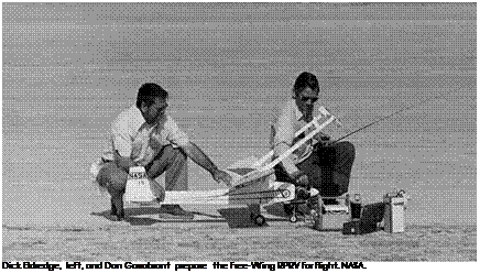
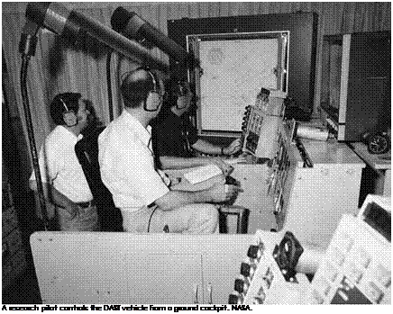
Encouraged by the results of the Hyper III experiment, Reed and his team decided to convert a full-scale production airplane into a RPRV. They selected the Flight Research Center’s modified Piper PA-30 Twin Comanche, a light, twin-engine propeller plane that was equipped with both conventional and fly-by-wire control systems. Technicians installed uplink/downlink telemetry equipment to transmit radio commands and data. A television camera, mounted above the cockpit windscreen, transmitted images to the ground pilot to provide a visual reference—a significant improvement over the Hyper III cockpit. To provide the pilot with physical cues, as well, the team developed a harness with small elec­tronic motors connected to straps surrounding the pilot’s torso. During maneuvers such as sideslips and stalls, the straps exerted forces to sim­ulate lateral accelerations in accordance with data telemetered from the RPRV, thus providing the pilot with a more natural "feel.”[895] The origi­nal control system of pulleys and cables was left intact, but a few minor modifications were incorporated. The right-hand, or safety pilot’s, con­trols were connected directly to the flight control surfaces via conven­tional control cables and to the nose gear steering system via pushrods. The left-hand control wheel and rudder pedals were completely inde­pendent of the control cables, instead operating the control surfaces via hydraulic actuators through an electronic stability-augmentation system.

Bungees were installed to give the left-hand controls an artificial "feel.” A friction control was added to provide free movement of the throttles while still providing friction control on the propellers when the remote throttle was in operation.

When flown in RPRV configuration, the left-hand cockpit controls were disabled, and signals from a remote control receiver fed directly into the control system electronics. Control of the airplane from the ground cockpit was functionally identical to control from the pilot’s seat. A safety trip channel was added to disengage the control system whenever the airborne remote control system failed to receive intelli­gible commands. In such a situation, the safety pilot would immedi­ately take control.[896] Flight trials began in October 1971, with research pilot Einar Enevoldson flying the PA-30 from the ground while Thomas C. McMurtry rode on board as safety pilot, ready to take con­trol if problems developed. Following a series of incremental buildup flights, Enevoldson eventually flew the airplane unassisted from takeoff to landing, demonstrating precise instrument landing system approaches, stall recovery, and other maneuvers.[897] By February 1973, the project was nearly complete. The research team had successfully developed and demonstrated basic RPRV hardware and operating techniques quickly and at relatively low cost. These achievements were critical to follow-on programs that would rely on the use of remotely piloted vehicles to reduce the cost of flight research while maintaining or expanding data return.[898]

Lessons Learned-Realities and Recommendations

Unmanned research vehicles have proven useful for evaluating new aeronautical concepts and providing precision test capability, repeat­able test maneuver capability, and flexibility to alter test plans as nec­essary. They allow testing of aircraft performance in situations that might be too hazardous to risk a pilot on board yet allow for a pilot in the loop through remote control. In some instances, it is more cost – effective to build a subscale RPRV than a full-scale aircraft.[1047] Experience with RPRVs at NASA Dryden has provided valuable lessons. First and foremost, good program planning is critical to any successful RPRV project. Research engineers need to spell out data objectives in as much detail as possible as early as possible. Vehicle design and test planning should be tailored to achieve these objectives in the most effective way. Definition of operational techniques—air launch versus ground launch, parachute recovery versus horizontal landing, etc.—are highly dependent on research objectives.

One advantage of RPRV programs is flexibility in regard to match­ing available personnel, facilities, and funds. Almost every RPRV project at Dryden was an experiment in matching personnel and equipment to operational requirements. As in any flight-test project, staffing is very important. Assigning an operations engineer and crew chief early in the design phase will prevent delays resulting from opera­tional and maintainability issues.[1048] Some RPRV projects have required only a few people and simple model-type radio-control equipment. Others involved extremely elaborate vehicles and sophisticated control systems. In either case, simulation is vital for RPRV systems development, as well as pilot training. Experience in the simulator helps mitigate some of the difficulties of RPRV operation, such as lack of sensory cues in the cock­pit. Flight planners and engineers can also use simulation to identify significant design issues and to develop the best sequence of maneu­vers for maximizing data collection.[1049] Even when built from R/C model stock or using model equipment (control systems, engines, etc.), an RPRV should be treated the same as any full-scale research airplane. Challenges inherent with RPRV operations make such vehicles more susceptible to mishaps than piloted aircraft, but this doesn’t make an RPRV expend­able. Use of flight-test personnel and procedures helps ensure safe oper­ation of any unmanned research vehicle, whatever its level of complexity.

Configuration control is extremely important. Installation of new software is essentially the same as creating a new airplane. Sound engineering judgments and a consistent inspection process can eliminate potential problems.

Knowledge and experience promote safety. To as large a degree as possible, actual mission hardware should be used for simulation and training. People with experience in manned flight-testing and develop­ment should be involved from the beginning of the project.[1050] The criti­cal role of an experienced test pilot in RPRV operations has been repeat­edly demonstrated. A remote pilot with flight-test experience can adapt to changing situations and discover system anomalies with greater flex­ibility and accuracy than an operator without such experience.

The need to consider human factors in vehicle and ground cock­pit design is also important. RPRV cockpit workload is comparable to that for a manned aircraft, but remote control systems fail to provide many significant physical cues for the pilot. A properly designed Ground Control Station will compensate for as many of these shortfalls as possible.[1051] The advantages and disadvantages of using RPRVs for flight research sometimes seem to conflict. On one hand, the RPRV approach can result in lower program costs because of reduced vehicle size and complexity, elimination of man-rating tests, and elimination of the need for life-support systems. However, higher program costs may result from a number of factors. Some RPRVs are at least as complex as manned vehicles and thus costly to build and operate. Limited space in small airframes requires development of min­iaturized instrumentation and can make maintenance more difficult. Operating restrictions may be imposed to ensure the safety of people on the ground. Uplink/downlink communications are vulnerable to outside interference, potentially jeopardizing mission success, and line-of-sight limitations restrict some RPRV operations.[1052] The cost of designing and building new aircraft is constantly rising, as the need for speed, agility, stores/cargo capacity, range, and survivability increases. Thus, the cost of testing new aircraft also increases. If flight-testing is curtailed, however, a new aircraft may reach production with undiscovered design flaws or idiosyncrasies. If an aircraft must operate in an environment or flight profile that cannot be adequately tested through wind tunnel or computer simulation, then it must be tested in flight. This is why high-risk, high-payoff research projects are best suited to use of RPRVs. High data-output per flight—through judicious flight planning—and elimination of physical risk to the research pilot can make RPRV operations cost-effective and worth­while.[1053] Since the 1960s, remotely piloted research vehicles have evolved continuously. Improved avionics, software, control, and telemetry sys­tems have led to development of aircraft capable of operating within a broad range of flight regimes. With these powerful research tools, scientists and engineers at NASA Dryden continue to explore the aeronautical frontier.