Airfoil Evolution and Its Application to General Aviation
In the early 1930s, largely thanks to the work of Munk, the NACA had risen to world prominence in airfoil design, such status evident when, in 1933, the Agency released a report cataloging its airfoil research and presenting a definitive guide to the performance and characteristics of a wide range of airfoil shapes and concepts. Prepared by Eastman
N. Jacobs, Kenneth E. Ward, and Robert M. Pinkerton, this document, TR-460, became a standard industry reference both in America and abroad.[785] The Agency, of course, continued its airfoil research in the 1930s, making notable advances in the development of high-speed airfoil sections and low-drag and laminar sections as well. By 1945, as valuable as TR-460 had been, it was now outdated. And so, one of the
most useful of all NACA reports, and one that likewise became a standard reference for use by designers and other aeronautical engineers in airplane airfoil/wing design, was its effective replacement prepared in 1945 by Ira H. Abbott, Albert E. von Doenhoff, and Louis S. Stivers, Jr. This study, TR-824, was likewise effectively a catalog of NACA airfoil research, its authors noting (with justifiable pride) that
Recent information of the aerodynamic characteristics of NACA airfoils is presented. The historical development of NACA airfoils is briefly reviewed. New data are presented that permit the rapid of the approximate pressure distribution for the older NACA four-digital and fivedigit airfoils, by the same methods used for the NACA 6-series airfoils. The general methods used to derive the basic thickness forms for NACA 6 and 7 series airfoils together with their corresponding pressure distributions are presented. Detailed data necessary for the application of the airfoils to wing design are presented in supplementary figures placed at the end of the paper.
This report includes an analysis of the lift, drag, pitching moment, and critical-speed characteristics of the airfoils, together with a discussion of the effects of surface conditions available data on high-lift devices. Problems associated with the later-control devices, leading edge air intakes, and interference is briefly discussed, together with aerodynamic problems of application.[786]
While much of this is best remembered because of its association with the advanced high-speed aircraft of the transonic and supersonic era, much was as well applicable to new, more capable civil transport and GA designs produced after the war.
Two key contributions to the jet-age expansion of GA were the supercritical wing and the wingtip winglet, both developments conceived by Richard Travis Whitcomb, a legendary NACA-NASA Langley aerody – namicist who was, overall, the finest aeronautical scientist of the postSecond World War era. More comfortable working in the wind tunnel than sitting at a desk, Whitcomb first gained fame by experimentally investigating the zero lift drag of wing-body combinations through the transonic flow regime based on analyses by W. D. Hayes.[787] His resulting "Area Rule” for transonic flow represented a significant contribution to the aerodynamics of high-speed aircraft, first manifested by its application to the so-called "Century series” of Air Force jet fighters.[788] Whitcomb followed area rule a decade later in the 1960s and derived the supercritical wing. It delayed the sharp drag rise associated with shock wave formation by having a flattened top with pronounced curvature towards its trailing edge. First tested on a modified T-2C jet trainer, and then on a modified transonic F-8 jet fighter, the supercritical wing proved in actual flight that Whitcomb’s concept was sound. This distinctive profile would become a key design element for both jet transports and high-speed GA aircraft in the 1980s and 1990s, offering a beneficial combination of lower drag, better fuel economy, greater range, and higher cruise speed exemplified by its application on GA aircraft such as the Cessna Citation X, the world’s first business jet to routinely fly faster than Mach 0.90.[789]
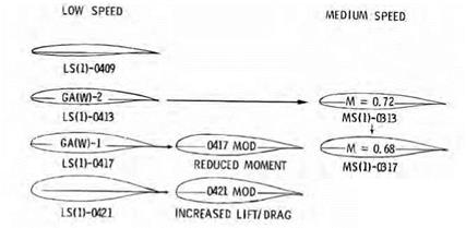
The application of Whitcomb’s supercritical wing to General Aviation began with the GA community itself, whose representatives approached Whitcomb after a Langley briefing, enthusiastically endorsing his concept. In response, Whitcomb launched a new Langley program, the Low-and – Medium-Speed Airfoil Program, in 1972. This effort, blending 2-D computer analysis and tests in the Langley Low-Turbulence Pressure Tunnel, led to development of the GA(W)-1 airfoil.[790] The GA(W)-1 employed a
 |
Low-and-Medium-Speed variants of the GA(W)-1 and -2 airfoil family. From NASA CP – 2046 (1979).
 |
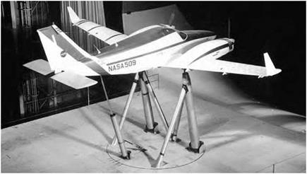
17-percent-thickness-chord ratio low-speed airfoil, offering a beneficial mix of low cruise drag, high lift-to-drag ratios during climbs, high maximum lift properties, and docile stall behavior.[791] Whitcomb’s team generated thinner and thicker variations of the GA(W)-1 that underwent its initial flight test validation in 1974 on NASA Langley’s Advanced
The Advanced Technology Light Twin-Engine airplane undergoing tests in the Langley 30 ft x 60 ft Full Scale Tunnel. NASA.
Technology Light Twin (ATLIT) engine airplane, a Piper PA-34 Seneca twin-engine aircraft modified to employ a high-aspect-ratio wing with a GA(W)-1 airfoil with winglets. Testing on ATLIT proved the practical advantages of the design, as did subsequent follow-on ground tests of the ATLIT in the Langley 30 ft x 60 ft Full-Scale-Tunnel.[792]
Subsequently, the NASA-sponsored General Aviation Airfoil Design and Analysis Center (GA/ADAC) at the Ohio State University, led by Dr. Gerald M. Gregorek, modified a single-engine Beech Sundowner light aircraft to undertake a further series of tests of a thinner variant, the GA(W)-2. GA/ADAC flight tests of the Sundowner from 1976-1977 confirmed that the Langley results were not merely fortuitous, paving the way for derivatives of the GA(W) family to be applied to a range of new aircraft designs starting with the Beech Skipper, the Piper Tomahawk, and the Rutan VariEze.[793]
Following on the derivation of the GA(W) family, NASA Langley researchers, in concert with industry and academic partners, continued refinement of airfoil development, exploring natural laminar flow (NLF) airfoils, previously largely restricted to exotic, smoothly finished sailplanes, but now possible thanks to the revolutionary development of smooth composite structures with easily manufactured complex shapes tailored to the specific aerodynamic needs of the aircraft under development.[794] Langley researchers subsequently blended their own conceptual and tunnel research with a computational design code developed at the University of Stuttgart to generate a new natural laminar flow airfoil section, the NLF(1).[795] Like the GA(W) before it, it served as the basis for various derivative sections. After flight testing on various testbeds, it was transitioned into mainstream GA design beginning with a derivative of the Cessna Citation II in 1990. Thereafter, it has become a standard feature of many subsequent aircraft.[796]
The second Whitcomb-rooted development that offered great promise in the 1970s was the so-called winglet.[797] The winglet promised to dramatically reduce energy consumption and reduce drag by minimizing the wasteful tip losses caused by vortex flow off the wingtip of the aircraft. Though reminiscent of tip plates, which had long been tried over the years without much success, the winglet was a more refined and
|
|
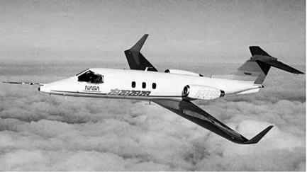
The Gates Learjet 28 Longhorn, which pioneered the application of Whitcomb winglets to a General Aviation aircraft. NASA.
better-thought-out concept, which could actually take advantage of the strong flow-field at the wingtip to generate a small forward lift component, much as a sail does. Primarily, however, it altered the span-wise distribution of circulation along the wing, reducing the magnitude and energy of the trailing tip vortex. First to use it was the Gates Learjet Model 28, aptly named the "Longhorn,” which completed its first flight in August 1977. The Longhorn had 6 to 8 percent better range than previous Lears.[798]
The winglet was experimentally verified for large aircraft application by being mounted on the wing tips of a first-generation jet transport, the Boeing KC-135 Stratotanker, progenitor of the civil 707 jetliner, and tested at Dryden from 1979-1980. The winglets, designed with a general – purpose airfoil that retained the same airfoil cross-section from root to tip, could be adjusted to seven different cant and incidence angles to enable a variety of research options and configurations. Tests revealed the winglets increased the KC-135’s range by 6.5 percent—a measure of both aerodynamic and fuel efficiency—better than the 6 percent projected by Langley wind tunnel studies and consistent with results obtained with the Learjet Longhorn. With this experience in hand, the winglet was swiftly applied to GA aircraft and airliners, and today, most airliners, and many GA aircraft, use them.[799]


