Category NASA’S CONTRIBUTIONS TO AERONAUTICS

The Future of the Tunnel in the Era of CFD

A longstanding flaw with wind tunnels was the aerodynamic interfer­ence caused by the "sting,” or the connection between the model and the test instrumentation. Researchers around the world experimented with magnetic suspension systems beginning in the late 1950s. Langley,

in collaboration with the AEDC, constructed the 13-Inch Magnetic Suspension and Balance System (MSBS). The transparent test section measured about 12.6 inches high and 10.7 inches wide. Five powerful electromagnets installed in the test section suspended the model and pro­vided lift, drag, side forces, and pitching and yaw moments. Control of the iron-cored model over these five axes removed the need for a model support. The lift force of the system enabled the suspension of a 6-pound iron-cored model. The rest of the tunnel was conventional: a continual – flow, closed-throat, open-circuit design capable of speeds up to Mach 0.5.[614]

When the 13-Inch MSBS became operational in 1965, NASA used the tunnel for wake studies and general research. Persistent problems with the system led to its closing in 1970. New technology and renewed interest revived the tunnel in 1979, and it ran until the early 1990s.[615]

NASA’s work on magnetic suspension and balance systems led to a newfound interest in a wind tunnel capable of generating cryogenic test temperatures in 1971. Testing a model at below -150 °F permitted the­oretically an increase in Reynolds number. There was a precedent for a cryogenic wind tunnel. R. Smelt at the Royal Aircraft Establishment at Farnborough conducted an investigation into the use of airflow at cryo­genic temperatures in a wind tunnel. His work revealed that a cryogenic wind tunnel could be reduced in size and required less power as com­pared with a similar ambient temperature wind tunnel operated at the same pressure, Mach number, and Reynolds number.[616]

The state of the art in cooling techniques and structural materials required to build a cryogenic tunnel did not exist in the 1940s. American and European interest in the development of a transonic tunnel that gen­erated high Reynolds numbers, combined with advances in cryogenics and structures in the 1960s, revived interest in Smelt’s findings. A team of Langley researchers led by Robert A. Kilgore initiated a study of the viability of a cryogenic wind tunnel. The first experiment with a low-

speed tunnel during summer 1972 resulted in an extension of the pro­gram into the transonic regime. Kilgore and his team began design of the tunnel in December 1972, and the Langley Pilot Transonic Cryogenic Tunnel became operational in September 1973.[617]

The pilot tunnel was a continual-flow, fan-driven tunnel with a slot­ted octagonal test section, 0.3 meters (1 foot) across the flats, and was constructed almost entirely out of aluminum alloy. The normal test medium was gaseous nitrogen, but air could be used at ambient temper­atures. The experimental tunnel provided true simulation of full-scale transonic Reynolds numbers (up to 100 x 106 per foot) from Mach 0.1 to 0.9 and was a departure from conventional wind tunnel design. The key was decreasing air temperature, which increased the density and decreased the viscosity factor in the denominator of the Reynolds num­ber. The result was the simulation of full-scale flight conditions at tran­sonic speeds with great accuracy.[618]

Kilgore and his team’s work generated fundamental conclusions about cryogenic tunnels. First, cooling with liquid nitrogen was prac­tical at the power levels required for transonic testing. It was also sim­ple to operate. Researchers could predict accurately the amount of time required to cool the tunnel, a basic operational parameter, and the amount of liquid nitrogen needed for testing. Through the use of a simple liquid nitrogen injection system, tunnel personnel could con­trol and evenly distribute the temperature. Finally, the cryogenic tunnel was quieter than was an identical tunnel operating at ambient temper­ature. The experiment was such a success and generated such promis­ing results that NASA reclassified the temporary tunnel as a "permanent” facility and renamed it the 0.3-Meter Transonic Cryogenic Tunnel (TCT).[619]

The Future of the Tunnel in the Era of CFD

The 0.3-Meter Transonic Cryogenic Tunnel. NASA.

After 6 years of operation, NASA researchers shared their experi­ences at the First International Symposium on Cryogenic Wind Tunnels at the University of Southampton, England, in 1979. Their operation of the 0.3-Meter TCT demonstrated that there were no insurmountable problems associated with a variety of aerodynamic tests with gaseous nitrogen at transonic Mach numbers and high Reynolds numbers. The

team found that the injection of liquid nitrogen into the tunnel circuit to induce cryogenic cooling caused no problems with temperature dis­tribution or dynamic response characteristics. Not everything, however, was known about cryogenic tunnels. There would be a significant learn­ing process, which included the challenges of tunnel control, run logic, economics, instrumentation, and model technology.[620]

Developments in computer technology in the mid-1980s allowed con­tinual improvement in transonic data collection in the 0.3-Meter TCT, which alleviated a long-term problem with all wind tunnels. The walls, floor, and ceiling of all tunnels provided artificial constraints on flight simulation. The installation of computer-controlled adaptive, or "smart,” tunnel walls in March 1986 lessened airflow disturbances, because they allowed the addition or expulsion of air through the expansion and con­traction along the length, width, and height of the tunnel walls. The result was a more realistic simulation of an aircraft flying in the open atmosphere. The 0.3-Meter TCT’s computer system also automatically tailored Mach number, pressure, temperature, and angle of attack to a specific test program and monitored the drive, electrical, lubrication, hydraulic, cooling, and pneumatic systems for dangerous leaks and fail­ures. The success of the 0.3-Meter TCT led to further investigation of smart walls at Langley and Lewis.[621]

NASA’s success with the 0.3-Meter Transonic Cryogenic Tunnel led to the creation of the National Transonic Facility (NTF) at Langley. Both NASA and the Air Force were considering the construction of a large transonic wind tunnel. NASA proposed a larger cryogenic tunnel, and the Air Force wanted a Ludweig-tube tunnel. The Federal Government decided in 1974 to fund a facility to meet commercial, military, and sci­entific needs based on NASA’s pioneering operation of the cryogenic tun­nel. Contractors built the tunnel on the site of the 4-Foot Supersonic Pressure Tunnel and incorporated the old tunnel’s drive motors, sup­port buildings, and cooling towers.[622]

Becoming operational in 1983, the NTF was a high-pressure, cryo­genic, closed-circuit wind tunnel with a Mach number range from 0.1 to 1.2 and a Reynolds number range of 4 x 10⁶ to 145 x 106 per foot. It featured a 2.5-meter test section with 12 slots and 14 reentry flaps in the ceiling and floor. Langley personnel designed a drive system to include a fan with variable inlet guide vanes for precise Mach number control. Injected as super-cold liquid and evaporated into a gas, nitro­gen is the primary test medium. Air is the test gas in the ambient tem­perature mode, while a heat exchanger maintains the tunnel temperature. Thermal insulation of the tunnel’s pressure shell ensured minimal energy consumption. The NTF continues to be one of Langley’s more advanced facilities as researchers evaluate the stability and control, cruise perfor­mance, stall buffet onset, and aerodynamic configurations of model air­craft and airfoil sections.[623]

The movement toward the establishment of national aeronautical facilities led NASA to expand the operational flexibility of the highly suc­cessful subsonic 40- by 80-foot wind tunnel at Ames Research Center. A major renovation project added an additional 80- by 120-foot test section capable of testing a full-size Boeing 737 airliner, making it the world’s largest wind tunnel. A central drive system that featured fans almost 4 stories tall and electric motors capable of generating 135,000 horsepower created the airflow for both sections through movable vanes that directed air through either section. The 40- by 80-foot test section acted as a closed circuit up to 345 mph. The air driven through the 80- by 120-foot test section traveled up to 115 mph before exhausting into the atmosphere. Each section incorporated a range of model supports to facilitate a variety of experiments. The two sections became opera­tional in 1987 (40- by 80-foot) and 1988 (80- by 120-foot). NASA chris­tened the tunnel the National Full-Scale Aerodynamics Complex (NFAC) at Ames Research Center.[624]

The Future of the Tunnel in the Era of CFD

A Pathfinder I advanced transport model being prepared for a test in the super-cold nitrogen and high-pressure environment of the National Transonic Facility (NTF) in 1986. NASA.

Spin Research

One of the areas of greatest interest has been that of spin behavior. When an airplane stalls, it may enter a spin, typically following a steeply

descending flightpath accompanied by a rotational motion (sometimes accompanied by other rolling and pitching motions) that is highly dis­orientating to a pilot. Depending on the dynamics of the entry and the design of the aircraft, it may be easily recoverable, difficult to recover from, or irrecoverable. Spins were a killer in the early days of aviation, when their onset and recovery phenomena were imperfectly understood, but have remained a dangerous problem since, as well.[840] Using special­ized vertical spin tunnels, the NACA, and later NASA, undertook exten­sive research on aircraft spin performance, looking at the dynamics of spins, the inertial characteristics of aircraft, the influence of aircraft design (such as tail placement and volume), corrective control input, and the like.[841]

As noted, spins have remained an area of concern as aviation has pro­gressed, because of the strong influence of aircraft configuration upon spin behavior. During the early jet age, for example, the coupled motion dynamics of high-performance low-aspect-ratio and high-fineness-ratio jet fighters triggered intense interest in their departure and spin charac­teristics, which differed significantly from earlier aircraft because their mass was now primarily distributed along the longitudinal, not lateral, axis of the aircraft.[842] Because spins were not a normal part of GA flying operations, GA pilots often lacked the skills to recognize and cope with spin-onset, and GA aircraft themselves were often inadequately designed to deal with out-of-balance or out-of-trim conditions that might force a spin entry. If encountered at low altitude, such as approach to landing, the consequences could be disastrous. Indeed, landing accidents com­posed more than half of all GA accidents, and of these, as one NASA document noted, "the largest single factor in General Aviation fatal acci­dents is the stall/spin.”[843]

The Flight Research Center’s 1966 study of comparative handling qualities and behavior of a range of GA aircraft had underscored
the continuing need to study stall-spin behavior. Accordingly, in the 1970s, NASA devoted particular attention to studying GA spins (and con­tinued studying the spins of high-performance aircraft as well), mark­ing "the most progressive era of NASA stall/spin research for general aviation configurations.”[844] Langley researchers James S. Bowman, Jr.; James M. Patton, Jr.; and Sanger M. Burk oversaw a broad program of stall/spin research. They and other investigators evaluated tail location and its influence upon spin recovery behavior using both spin-tunnel models,[845] and free-flight tests of radio-controlled models and actual air­craft at the Wallops Flight Center, on the Virginia coast of the Delmarva Peninsula.[846] Between 1977 and 1989, NASA instrumented and modified four aircraft of differing configuration for spin research: an experimental low-wing Piper design with a T-tail, a Grumman American AA-1 Yankee modified so that researchers could evaluate three different horizontal tail positions, a low-wing Beech Sundowner equipped with wingtip rockets to aid in stopping spin rotation, and a high-wing Cessna C-172. Overall, the tests revealed the critical importance of designers ensuring that the vertical fin and rudder of their new GA aircraft be in active air­flow during a spin, so as to ensure their effectiveness in spin recovery. To do that, the horizontal tail needed to be located in such a position on the aft fuselage or fin so as not to shield the vertical fin and rudder from active flow. The program was not without danger and incident. Mission planners prudently equipped the four aircraft with an emergency 10.5-ft – diameter spin-recovery parachute. Over that time, the ‘chute had to be deployed on 29 occasions when the test aircraft entered unrecoverable
spins; each of the four aircraft deployed the ‘chute at least twice, a mea­sure of the risk inherent in stall-spin testing.[847]

Подпись: 8

Подпись: Aircraft entering wake vortex flow encountered a series of dangers, ranging from upset to structural failure, depending on their approach to the turbulent flow. From NASA SP-409 (1977).

NASA’s work in stall-spin research has continued, but at a lower level of effort than in the heyday of the late 1970s and 1980s, reflecting changes in the Agency’s research priorities, but also that NASA’s work had mate­rially aided the understanding of spins, and hence had influenced the data and experience base available to designers shaping the GA aircraft of the future. As well, the widespread advent of electronic flight con­trols and computer-aided flight has dramatically improved spin behav­ior. Newer designs exhibit a degree of flying ease and safety unknown to earlier generations of GA aircraft. This does not mean that the spin is a danger of the past—only that it is under control. In the present and future, as in the past, ensuring GA aircraft have safe stall/spin behav­ior will continue to require high-order analysis, engineering, and test.

The British Invasion: CHIRP and HIRM Support the Tornado

In 1981, researchers at NASA Dryden assisted with the first of several series of tests for the British Royal Aircraft Establishment (RAE) under an international agreement to collect data relevant to the Panavia Tornado jet fighter, a large-scale NATO acquisition program. The variable-wing- sweep Tornado eventually became a major deep-strike attack aircraft used by the British, then-West German, and Italian air forces. Britain’s Royal Air Force flew an interceptor variant as well. During the 6-week Cooperative High Incidence Research Program (CHIRP), 4 25-percent – scale Tornado models of varying configurations were used to conduct 10 drop tests. Six of these flights were undertaken to gather unaugmented stability and control data to improve RAE engineers’ mathematical model of Tornado aerodynamics. The remaining 4 drops (totaling 130 seconds of flight time) were allocated to evaluating a Spin Prevention and Incidence-Limiting System (SPILS) in support of a modification program for the full-scale operational Tornado fleet.

In February and March 1981, NASA and RAE officials met to discuss support requirements for the project. Once details had been decided, Walter B. Olstad of NASA’s Office of Aeronautics and Space Technology and R. J.E. Glenny of the British RAE signed a Memorandum of Agreement. The first Tornado model arrived at Dryden in a British Royal Air Force C-130 transport May 11. Edward "Ted” Jeffries and Owen Forder of the RAE arrived a week later to assemble the model and install NASA telemetry equipment. Three more Tornado models arrived at the end of July.[966] The quarter-scale models were constructed of fiberglass, wood, and metal. Each was equipped with a rudder and an all-moving tailplane with differential deflection. Instrumentation included transducers, telemetry, servo systems, and radar transponder equipment. To reduce complexity and cost, the models were not equipped with landing gear. Instead, recovery parachutes were provided to allow for a soft landing in the desert. Each model weighed approximately 661 pounds and was towed aloft beneath a helicopter, using a 98-foot cable with an electromechanical release system. A small drogue chute stabilized the model prior to drop in order to maintain proper heading, and it separated at launch. An onboard, preprogrammed controller actuated the model’s control surfaces. From a launch altitude of 11,900 feet, each model had a maximum gliding range of about 4.7 miles.[967] The British team, consisting of Jeffries, Forder, Charles O’Leary, Geraldine F. Edwards, and Jim Taylor, had the first model ready for flight by August 25. Dubbed ADV-B—reflecting its shape, which was that of the so-called long-nose Air Defense Variant (ADV) of the Tornado design— the model was carried aloft August 31 beneath a UH-1H on loan from NASA Ames Research Center. The helicopter was piloted by Army Maj. Ron Carpenter and NASA research pilot Donald L. Mallick, with O’Leary as observer. Following release from its tow cable, the Tornado model glided to a landing on the Precision Impact Range Area, east of Rogers Dry Lake.

Tornado model ADV-C was dropped the next day, and ADV-D followed with a test on September 3. Five days later, the fourth model—called IDS-I for Interdiction Strike configuration (the snub-nose surface attack variant of the Tornado)—was successfully dropped over the PIRA. By September 22, the ADV-B and ADV-D models had each flown three more times.[968] Although three of the models were unserviceable at the completion of the tests because of damage sustained during recovery, CHIRP constituted an outstanding success. Previous flights had been made at test ranges near Larkhill, U. K., and Woomera, Australia, but with less impressive results, so much less so that the data acquired during testing at Dryden was equiv­alent to that collected during 5 years of earlier tests at other locations.

A second test series involving the three Tornado variants previously flown, along with two High-Incidence Research Model (HIRM) vehicles, took place in 1983. The HIRM shape included a boxy fuselage, conven­tional tail configuration, and close-coupled canards in front of the wings. On July 6, the first of two HIRM models flew once at Larkhill to test all systems and basic aerodynamics.

Following arrival of the test team at Dryden, the first model was ready for flight by September 23, but the mission was canceled because of adverse weather. ADV-D was successfully dropped 4 days later. The following day, the IDS-I model was flown but was damaged during land­ing and did not fly again. Two more flights each were made with the ADV-D and ADV-B models in October.[969] The remaining sorties were flown using the two HIRM models, dubbed "Hirmon” and "Hermes.” Unlike the Tornado models, these did not resemble an operational air­craft type. Rather, they represented an entirely new research aircraft configuration. The HIRM models were equipped with an active control system capable of maintaining bank angles below 30 degrees.

The first drop of Hirmon at Dryden was terminated after just 22 sec­onds of flight, when an overspeed sensor triggered the vehicle’s parachute recovery system. Hermes flew several days later, but the mission was termi­nated immediately after launch because of failure of a barometric switch in the recovery system. Successful flights of both HIRM vehicles com­menced October 14 and continued through the end of the month, when the test models were packed for shipping back to the United Kingdom.

Of the 20 flights scheduled at Dryden during a 6-week period, 5 were eventually canceled. Fifteen flights were completed successfully. The British team worked punishing 12-hour days and 6-day weeks to sustain the flight rate. Three models remained flyable at the conclusion of the project. One Tornado sustained repairable fuselage damage requiring an alignment fixture not available at Dryden, and a second Tornado sustained minor but extensive damage as the result of being dragged through a small tree after a successful parachute landing. The HIRM models were used in 10 of the flights in this series.[970] A third test series was conducted in 1986 under a joint agreement among NASA, the U. S. Department of Defense, and the British Ministry of Defence. A four-person test team traveled from the U. K. and was joined by five Ames-Dryden project team members who provided management and support-services coordination. The Air Force Flight Test Center and U. S. Army Aviation Engineering Flight Activity group at Edwards provided additional support. Typically, an Army UH-1H heli­copter carried the test model to an altitude of between 10,000 to 11,500 feet and released it over the PIRA at 72 to 78 knots indicated airspeed.

Three Tornado and the two HIRM models arrived at Dryden in October. Hirmon and Hermes were flown 12 times, logging a total of 24.48 minutes of flight time. The Tornado models were not used, and

Hermes flew only once. Two flights resulted in no useful data. Five were canceled because of adverse weather, four because of helicopter unavail­ability, and five more because of range unavailability. Manual recovery had to be initiated during the third drop test. Both models survived the test series with minimal damage.[971]

NASA’s Valkyrie Supersonic Cruise Flight-Test Program

Although the XB-70 test program was only budgeted for 180 hours, Air Force Category 1 testing with the contractor took first priority. That test­ing included verification of basic airworthiness and the achievement of the contractually required speed of Mach 3 for an extended cruise period. This proved to be harder than was thought, as the first XB-70 turned out to be almost a jinxed aircraft, as prototypes often are.

It was not until the 17th flight, 13 months after 1st flight, that Mach 3 was attained. Earlier flights had been plagued by landing gear problems, in-flight shutdowns of the new GE J93 engines (the most powerful in the world, at 30,000 pounds of thrust each in afterburner), and, most seriously, in-flight shedding of pieces of the stainless steel skin. The stainless steel honeycomb covering much of the wing had proven to be difficult to fabricate, requiring a brazing technique in an inert atmo­sphere to attach the skins. This process unfortunately resulted in numer­ous pinholes in the skin welds, which would allow the nitrogen inerting atmosphere required for fuel tanks with fuel heated to over 300 °F to leak away. Correcting this problem delayed the first aircraft by almost a year. The No. 5 fuel tank could never be sealed and was flown empty, further shortening the duration of test sorties on the two prototype air­craft, which had no aerial refueling capability.[1077]

Подпись: 10Aside from the mechanical difficulties that often shortened test sorties, the design features providing supersonic cruise worked well. The two-pilot XB-70 was initially the heaviest airplane in the world, at 500,000-pound takeoff weight, as well as designed to be the fastest. It was stable, maneuverable, and, aside from the unusually high attitude of the cockpit on takeoff and landing, easy to fly. The folding wingtips (each the size of a B-58 wing) worked flawlessly. The propulsion system of inlets and turbojets, when properly functioning, provided the thrust to reach Mach 3, and handling qualities at that speed were generally satisfactory, although the high speed meant that small pitch changes produced large changes in vertical velocity; it was difficult to maintain level flight manually. Mach 3 cruise in a large SST-size airplane seemed to be technologically achievable.[1078]

The inlets for the six engines were another story for complexity, criticality, and pilot workload. An air inlet control system used moving ramps and doors to control the geometry of the inlet to position shock waves in the inlet above flight speed of Mach 1.6.[1079] The final shock wave in the inlet was a strong normal shock in the narrow "throat,” where the airflow became subsonic downstream of the shock. Proper position­ing of the normal shock was vital; if downstream pressure was too high,
the normal shock might "pop out” of the inlet, losing the inlet pressure buildup, which actually provided net thrust to the airplane, and caus­ing compressor stalls in the turbojet, as it now received air that was still supersonic. This was known as an inlet " unstart” and usually was cor­rected by opening bypass doors in the inlet to relieve the pressure and resetting the inlet geometry to allow the normal shock to resume its cor­rect position. Unstarts usually were announced by a loud bang, a rapid yaw in the direction of the inlet that had unstarted because of the lack of thrust, and often by an unstart of the other inlet because of airflow disturbance caused by the yaw. Pilots considered unstarts to be exciting (" breathtaking,” as NAA test pilot Al White described it), with motion varying from mild to severe, depending on flight conditions, but not par­ticularly dangerous and usually easily corrected.[1080] Although the inlet control system was designed to be automatic, for the first XB-70 (also known as "Ship 1”), the copilot became the flight engineer and manu­ally manipulated the ramps and doors as a function of Mach number and normal shock position indicator. There were two inlets on the air­craft, with each feeding three engines. There had been some concern that problems with one engine might spread to the other two fed by the same inlet, but this did not seem to usually be the case. One excep­tion was on the 12th flight, on May 7, 1965, when a piece of stainless steel skin went down the right inlet at Mach 2.6, damaging all 3 engines, one seriously. The mismanagement of the right inlet doors, because of time pressure and lack of knowledge of the nature of the emergency, led to inlet "duct buzz” pressure fluctuations caused by shock oscillation. This vibration at 2% cycles per second was near the duct’s resonant fre­quency, which could cause destruction of the duct. The vibration also fed into the highly flexible vehicle fuselage. This in turn led to the pilot reverting to turning the yaw dampers off, with subsequent development of a divergent Dutch roll oscillation. All three engines on the right side were eventually shut down. Fortunately, the flight control anomalies were cleared up, and the pilot performed a successful "3 and % engine” landing on the Rogers dry lakebed, touching down at 215 knots. This 5-minute inlet emergency generated a 33-page analytical report and presented some cautionary notes. The author commented in his clos­ing that: "The seriousness of the interaction of the inlet conditions with
vehicle performance and handling characteristics tends to be accentu­ated for high-supersonic aircraft. Bypass-door settings are critical on mixed-compression inlets to maintain efficient inlet conditions.”[1081] This observation would prove even more relevant for the Mach 3 Blackbird aircraft that followed the XB-70 in NASA supersonic cruise research. Test crews soon discovered that, as Blackbird researchers rue­fully noted, "Around Mach 3, when things go wrong, they also get worse at a rate of Mach 3.”[1082] Crews who flew the secret twin-engine Blackbird often experienced this fact of life, sometimes with a less happy ending.

The Way Ahead for SVS

NASA’s long heritage of research in synthetic vision has generated use­ful concepts, demonstrations of key technological breakthroughs, and prototype systems and architectures that have influenced both the pri­vate and public sectors. Much of this work has been accomplished by small teams of dedicated researchers, often using creative approaches and management styles far removed from typical big management prac­tices. As this book goes to press, synthetic vision and advanced flight path guidance constitutes a critical piece of the Agency’s future work on Integrated Intelligent Flight Deck Technologies and related activi­ties aimed at fulfilling the promise of better air transportation and mil­itary airpower. While long-range institutional and national budgetary circumstances add greater uncertainties to the challenge of forecast­ing the future, it is clear that as the advent of blind-flying instrumenta­tion transformed aviation safety and utility in the interwar years, the advent of synthetic vision will accomplish the same in the first years of the 21st century, furnishing yet another example of the enormous and continuing contributions of NASA and its people to the advancement of aeronautics.

The Way Ahead for SVS

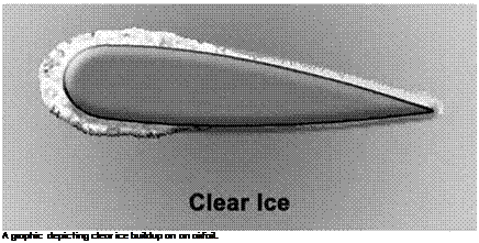
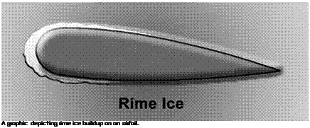
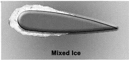
Ice formation on aircraft poses a serious flight safety hazard. Here a NASA technician measures ice deposits on a test wing in NASA’s Icing Research Tunnel, Lewis (now Glenn) Research Center, Ohio. NASA.

Care-Free Maneuverability At High Angle of Attack

Joseph R. Chambers

L

Подпись: 13Since the airplane’s earliest days, maintaining safe flight at low speeds and high angles of attack has been a stimulus for research. As well, ensuring that a military fighter aircraft has good high-angle-of-attack qualities can benefit its combat capabilities. NASA research has pro­vided critical guidance on configuration effects and helped usher in the advent of powerful flight control concepts.

A

T THE TIME THAT the National Aeronautics and Space Administration (NASA) absorbed the National Advisory Committee for Aeronautics (NACA), it also inherited one of the more challenging technical issues of the NACA mission: to "supervise and direct the scientific study of the problems of flight with a view to their practical solution.” Since the earliest days of heavier-than-air flight, intentional or inadvertent flight at high angles of attack (high alpha) results in the onset of flow separation on lifting surfaces, stabilizing fins, and aerodynamic controls. In such conditions, a poorly designed air­craft will exhibit a marked deterioration in stability, control, and flying qualities, which may abruptly cause loss of control, spin entry, and cat­astrophic impact with the ground.[1273] Stalling and spinning have been— and will continue to be—major areas of research and development for civil and military aircraft. In the case of highly maneuverable military aircraft, high-angle-of-attack characteristics exert a tremendous influ­ence on tactical effectiveness, maneuver options, and safety.

Some of the more notable contributions of NASA to the Nation’s military aircraft community have been directed at high-angle-of-attack technology, including the conception, development, and validation of advanced ground – and flight-test facilities; advances in related disci­plinary fields, such as aerodynamics and flight dynamics; generation
of high-alpha design criteria and methods; and active participation in aircraft development programs.[1274] Applications of these NASA contribu­tions by the industry and the Department of Defense (DOD) have led to a dramatic improvement in high-angle-of-attack behavior and asso­ciated maneuverability for the current U. S. military fleet. The scope of NASA activities in this area includes ground-based and flight research at all of its aeronautical field centers. The close association of NASA, industry, and DOD, and the significant advances in the state of the art that have resulted from common objectives, are notable achievements of the Agency’s value to the Nation’s aeronautical achievements.

Challenges

Подпись: 13As clearly evidenced by U. S. military experiences, the technical area of high-angle-of-attack/departure/spin behavior will continue to challenge design teams of highly maneuverable aircraft. The Nation has been for­tunate in assembling and maintaining unique expertise and facilities for the timely identification and resolution of problems that might have had a profound impact on operational capability or program viability. In the author’s opinion, several situations are emerging that threaten the tra­ditional partnerships and mutual resources required for advancing the state of the art in high-angle-of-attack technology for military aircraft.

The end of the Cold War has naturally resulted in a significant decrease in new military aircraft programs and the need for continued research in a number of traditional research areas. As technical person­nel exit from specialty areas such as high-angle-of-attack and spin behav­ior, the corporate knowledge and experience base that was the jewel in NASA’s crown rapidly erodes, and lessons learned become forgotten.

Of even more concern is the change in traditional working-level relationships between the NASA and DOD communities. During the term of NASA Administrator Daniel S. Goldin in the 1990s, NASA turned its priorities away from its traditional links with military aircraft R&D to the extent that long-time working-level relationships between NASA, indus­try, and DOD peers were ended. At the same time, aeronautics funding within the Agency was significantly reduced, and remaining aeronautics activities were redirected to civil goals. As a result of those programmatic decisions and commitments, NASA does not even highlight military – related research as part of its current mission. It has become virtually impossible for researchers and their peers in the military, industry, or DOD research laboratories to consider the startup of highly productive, unclassified military-related programs such as the NASA F/A-18 High – Angle-of-Attack Technology program.

Meanwhile, leaders in military services and research organiza­tions have now been replaced with many who are unfamiliar with the traditional NASA-military ties and accomplishments. Without those
relationships, the military R&D organizations have turned to hiring their own aeronautical talent and conducting major research undertakings in areas that were previously exclusive to NASA Centers.

Finally, one of the more alarming trends underway has been the massive closures of NASA wind tunnels, which have been the backbone of NASA’s ability to explore concepts and ideas and to respond to high – priority military requests and problem-solving exercises in specialty areas such as high-angle-of-attack technology.

Подпись: 13In summary, this essay has discussed some of the advances made in high-angle-of-attack technology by NASA, which have contributed to a dramatic improvement in the capabilities of the Nation’s first-line mil­itary aircraft. Without these contributions, many of the aircraft would have been subject to severe operational restrictions, excessive develop­ment costs, significantly increased risk, and unacceptable accidents and safety-of-flight issues. In the current era of relative inactivity for devel­opment of new aircraft, it is critical that the resources required to pro­vide such technology be protected and nurtured for future applications.

Challenges

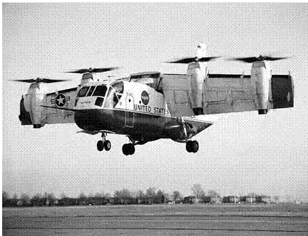
Three important NASA research aircraft representing different approaches to V/STOL flight pass in review over NASA’s Ames Research Center. Left to right: the deflected lift QSRA, the tilt rotor XV-15, and the vectored-thrust Harrier. NASA.

The Tu-144 Flight Experiments Project

Подпись: 15While negotiations were underway in 1993, leading to the agreement between the United States and Russia to return a Tu-144D to flight status as a supersonic flying laboratory, the HSR Program Office selected NASA Dryden to establish a Project Office for all Tu-144 activ­ities. This initially involved developing a rapport with a British com­pany, IBP, Ltd., which served as the business representative for Tupolev, now known as the Tupolev Aircraft Company (or Tupolev ANTK) after the economic evolution in Russia in the 1990s. Ken Szalai and IBP’s Judith DePaul worked to establish an effective business relationship, and this paid dividends in the ensuing complex relationships involving NASA, Rockwell, McDonnell-Douglas, Boeing, Tupolev, and IBP. A degree of cooperation flourished at a level not always observed in NASA-Russian partnerships. Having a business intermediary such as IBP navigate the paths of international business helped ensure the success of the Tu-144 experiment, according to Dryden Tu-144 Project Manager Russ Barber.[1464]

Originally, the Tu-144 flight experiment was envisioned as a 6-month, 30-flight program.[1465] As events unfolded, the experiment evolved into a two-phase operation. This was due, in part, to the inevitable delays in an enterprise of this magnitude and complexity, to learning from the results of the initial experiments, and to data acquisition issues.[1466] By 1995, after two meetings in Russia, the HSR Program Office, Boeing, Rockwell, McDonnell-Douglas, and Tupolev established the requirements for returning a Tu-144D to flight and fabricating an instrumentation system capable of supporting the postulated lineup of experiments.[1467] [1468] From a list of some 50 proposed experiments, the NASA, industry, and Tupolev officials selected 6 flight experiments for inclusion (a 7th was later added).11

A somewhat complex international organization developed that, despite the superficial appearance of duplication, ended up working very smoothly. NASA Dryden represented the HSR Program Office as the overseer for all Tu-144 activity. Boeing was contracted to install the instrumentation system, a complex task with over 700 individual pressure transducers, accelerometers, thermocouples, boundary layer rakes, pressure belts, microphones, and other sensors. NASA Dryden installed a complex French-built Damien digital data acquisition system (DAS) for five of the original six experiments.[1469] The remaining experiment, a NASA Langley Structure/Cabin Noise experiment, used its own Langley-built DAS.[1470] In a sense, traditional roles had to be adjusted, because Boeing, as the contractor, directed NASA, as the Government Agency and supplier, when to provide the necessary sensors and DAS.[1471] Boeing and Tupolev would install the sensors, and NASA would then calibrate and test them. The Damien DAS ultimately became problem­atic and led to some erroneous data recording in Phase I.[1472]

Подпись: 15Tupolev assumed the role of returning the selected Tu-144D, SSSR – 771114, to flight. This was no trivial matter. Even though 771114 had last flown in 1990, the engines were no longer supported and had to be replaced (as discussed in a subsequent section), which necessitated major modifications to the engine nacelles, elevons, and flight deck.[1473] As Tupolev was completing this work in 1995 and 1996, IBP acted as its business interface with NASA and Boeing.

In general, the HSR program funded the American effort. The cost to NASA for the Tu-144 flight experiment was $18.3 million for 27 flights. Boeing contributed $3.3 million, and it is estimated that Tupolev spent $25 million.[1474] Tupolev gained a fully instrumented and refurbished Tu-144, but unfortunately, after NASA canceled the HSR program in 1999, Tupolev could find no other customers for its airplane.

During the initial program definition and later during the aircraft modification, a number of HSR, Dryden, and Langley personnel made numerous trips to Zhukovsky. HSR managers coordinated program schedules and experiment details, Dryden personnel observed the return to flight efforts as well as the instrumentation modifications and pro­vided flight operations inputs, and Langley instrumentation technicians and researchers assisted with their experiment installation. Among the Dryden visitors to Zhukovsky was NASA research pilot Gordon Fullerton. Fullerton was the NASA pilot interface during these development years and worked with his Tupolev counterparts on flight deck and opera­tional issues. In an interview with the author, he recalled the many con­trasts in the program regarding the Russian and American methods of engineering and flight operations. Items worthy of minute detail to the Russians seemed trivial at times to the Americans, while American prac­tices at times resulted in confused looks from the Tupolev personnel. By necessity, because of a lack of computer assets, the Tupolev pilots, engi­neers, and technicians worked on a "back of the envelope” methodology. Involvement of multiple parties in decisions was thus restricted simply because of a lack of easy means to include them all. Carryovers from the Soviet days were still prevalent in the flightcrew distribution of duties, lack of flight deck instrumentation available to the pilots, and ground procedures that would be viewed as wholly inefficient by Western air­lines. Nevertheless, Tupolev produced an elegant airplane that could fly a large payload at Mach 2.[1475]

Подпись: 15As the American and Russian participants gained familiarity, a spirit of trust and cooperation developed that ultimately contributed to the project’s success. The means of achieving this trust were uniquely Russian. As the various American delegations arrived in Moscow or Zhukovsky, they were routinely feted to gala dinners with copious sup­plies of freely offered vodka. This was in the Russian custom of becom­ing acquainted over drinks, during which inhibitions that might mask hidden feelings were relaxed. The custom was repeated over and over again throughout the program. Few occasions passed without a cele­bratory party of some degree: preflight parties, postflight parties, wel­coming parties, and farewell parties were all on the agenda. Though at times challenging for some of the American guests who did not drink,

these social gatherings were very effective at cementing friendships among two peoples who only a few years before uneasily coexisted, with all of their respective major cities targeted by the other’s missiles. To a person, the Americans who participated in this program realized that on a personal level, the Russians were generous hosts, loyal friends, and trusted colleagues. If nothing else, this was a significant accomplish­ment for this program.

Подпись: 15Nineteen flights were completed by early 1998, achieving most of the original program goals. However, some data acquisition problems had rendered questionable some of the data from the six experiments.[1476] The HSR Program Office decided that it would be valuable to have United States research pilots evaluate the Tu-144 in order to develop corporate knowledge within NASA regarding SST handling qualities and to ascer­tain if the adverse handling qualities predicted by the data collected actu­ally existed. Furthermore, there were additional data goals developed since the inception of the program, and a seventh experiment was orga­nized. The resumption of the test flights was scheduled for September 1998. The HSR Program Office and Boeing selected Gordon Fullerton from Dryden and NASA research pilot Robert A. Rivers from Langley as the evaluation pilots. Fullerton had been the Dryden project pilot for the Tu-144 modification and refurbishment, and he was familiar with the Tupolev flightcrews and the airplane. Rivers had been the HSR project pilot for several years, had participated in every HSR flight simulation experiment, served on two HSR integrated test develop­ment teams, and had performed an extensive handling qualities eval­uation of the Concorde SST the previous year. To accompany them to Zhukovsky were two NASA flight control engineers, Timothy H. Cox from Dryden and E. Bruce Jackson from Langley, and Boeing Tu-144 project handling qualities engineer Norman H. Princen. Jackson had completed extensive work on flight control development for the HSCT Reference H model. During summer 1998, the team members worked together to develop a draft test plan, flew both the Ames and Langley 6-degree-of-freedom motion simulators with the Reference H model, and began studying the Tu-144 systems with the rudimentary information available in the United States at that time. On September 4, they departed for Zhukovsky.

Avionics

Lightning effects on avionics can be disastrous, as illustrated by the account of the loss of AC-67. Composite aircraft with internal radio anten­nas require fiberglass composite "windows” in the lightning-strike mesh near the antenna. (Fiberglass composites are employed because of their transparency to radio frequencies, unlike carbon fiber.) Lightning pro­tection and avoidance are important for planning and conducting flight tests. Consequently, NASA’s development of lightning warning and detec­tion systems has been a priority in furthering fly-by-wire (FBW) systems. Early digital computers in flight control systems encountered conditions in which their processors could be adversely affected by lightning-generated electrical pulses. Subsequently, design processes were developed to pro­tect electronic equipment from lightning strikes. As a study by the North Atlantic Treaty Organization (NATO) noted, such protection is "particu­larly important on aircraft with composite structures. Although equipment bench tests can be used to demonstrate equipment resistance to lightning strikes and EMP, it is now often considered necessary to perform whole aircraft lightning-strike tests to validate the design and clearance process.”[173]

Celeste M. Belcastro of Langley contrasted laboratory, ground-based, and in-flight testing of electromagnetic environmental effects, noting:

Laboratory tests are primarily open-loop and static at a few operating points over the performance envelope of the equipment and do not consider system level effects. Full-aircraft tests are also static with the aircraft situated on the ground and equipment powered on during expo­sure to electromagnetic energy. These tests do not pro­vide a means of validating system performance over the operating envelope or under various flight conditions. . . .

The assessment process is a combination of analysis, sim­ulation, and tests and is currently under development for demonstration at the NASA Langley Research Center. The assessment process is comprehensive in that it addresses (i) closed-loop operation of the controller under test, (ii) real-time dynamic detection of controller malfunctions that occur due to the effects of electromagnetic distur­bances caused by lightning, HIRF, and electromagnetic interference and incompatibilities, and (iii) the resulting effects on the aircraft relative to the stage of flight, flight conditions, and required operational performance.[174]

A prime example of full-system assessment is the F-16 Fighting Falcon, nicknamed "the electric jet,” because of its fly-by-wire flight con­trol system. Like any operational aircraft, F-16s have received lightning strikes, the effects of which demonstrate FCS durability. Anecdotal evi­dence within the F-16 community contains references to multiple light­ning strikes on multiple aircraft—as many as four at a time in close formation. In another instance, the leader of a two-plane section was struck, and the bolt leapt from his wing to the wingman’s canopy.

Aircraft are inherently sensor and weapons platforms, and so the lightning threat to external ordnance is serious and requires exami­nation. In 1977, the Air Force conducted tests on the susceptibility of AIM-9 missiles to lightning strikes. The main concern was whether the Sidewinders, mounted on wingtip rails, could attract strobes that could enter the airframe via the missiles. The evaluators concluded that the optical dome of the missile was vulnerable to simulated lightning strikes even at moderate currents. The AIM-9’s dome was shattered, and burn marks were left on the zinc-coated fiberglass housing. However, there was no evidence of internal arcing, and the test concluded that "it is unlikely that lightning will directly enter the F-16 via AIM-9 missiles.”[175] Quite clearly, lightning had the potential of damaging the sensitive optics and sensors of missiles, thus rendering an aircraft impotent. With the increasing digitization and integration of electronic engine controls, in addition to airframes and avionics, engine management systems are now a significant area for lightning resistance research.

National Aviation Operations Monitoring Service

A further contribution to the Aviation Safety Monitoring and Modeling project provided yet another method for gathering data and crunch­ing numbers in the name of making the Nation’s airspace safer amid increasingly crowded skies. Whereas the Aviation Safety Reporting System involved volunteered safety reports and the Performance Data Analysis and Reporting System took its input in real time from digital data sources, the National Aviation Operations Monitoring Service was a scientifically designed survey of the aviation community to generate statistically valid reports about the number and frequency of incidents that might compromise safety.[242]

After a survey was developed that would gather credible data from anonymous volunteers, an initial field trial of the NAOMS was held in 2000, followed by the launch of the program in 2001. Initially, the sur­veyors only sought out air carrier pilots who were randomly chosen from the FAA Airman’s Medical Database. Researchers characterized the response to the NAOMS survey as enthusiastic. Between April 2001 and December 2004, nearly 30,000 pilot interviews were completed, with a remarkable 83-percent return rate, before the project ran short of funds and had to stop. The level of response was enough to achieve statistical validity and prove that NAOMS could be used as a perma­nent tool for managers to assess the operational health of the ATC sys­tem and suggest changes before they were actually needed. Although NASA and the FAA desired for the project to continue, it was shut down on January 31, 2008.[243]

It’s worth mentioning that the NAOMS briefly became the sub­ject of public controversy in 2007, when NASA received a Freedom of Information Act request by a reporter for the data obtained in the NAOMS survey. NASA denied the request, using language that then NASA Administrator Mike Griffin said left an "unfortunate impression” that the Agency was not acting in the best interest of the public. NASA eventually released the data after ensuring the anonymity originally guaranteed to those who were surveyed. In a January 14, 2008, letter from Griffin to all NASA employees, the Administrator summed up the experience by writing: "As usual in such circumstances, there are les­sons to be learned, remembered, and applied. The NAOMS case dem­onstrates again, if such demonstrations were needed, the importance of peer review, scientific integrity, admitting mistakes when they are made, correcting them as best we can, and keeping our word, despite the crit­icism that can ensue.”[244]