Category NASA’S CONTRIBUTIONS TO AERONAUTICS

The NACA and the Wind Tunnel

For the United States, the Great War highlighted the need to achieve parity with Europe in aeronautical development. Part of that effort was the creation of the Government civilian research agency, the NACA, in March 1915. The committee established its first facility, Langley Memorial Aeronautical Laboratory—named in honor of aeronautical experimenter and Smithsonian Secretary Samuel P. Langley—2 years

The NACA and the Wind Tunnel

NACA Wind Tunnel No. 1 with a model of a Curtiss JN-4D Trainer in the test section. NASA.

later near Hampton, VA, on the Chesapeake Bay. In June 1920, NACA Wind Tunnel No. 1 became operational. A close copy of a design built at the British National Physical Laboratory a decade earlier, the tunnel produced no data directly applicable to aircraft design.[536]

One of the major obstacles facing the effective use of a wind tun­nel was scale effects, meaning the Reynolds number of model did not match the full-scale airplane. Prandtl protege Max Munk proposed the construction of a high-pressure tunnel to solve the problem. His Variable Density Tunnel (VDT) could be used to test a 1/20th-scale model in an airflow pressurized to 20 atmospheres, which would generate identical Reynolds numbers to full-scale aircraft. Built in the Newport News shipyards, the VDT was radical in design with its boilerplate and rivets. More importantly, it proved to be a point of departure from pre­vious tunnels with the data that it produced.[537]

The VDT became an indispensable tool to airfoil development that effectively reshaped the subsequent direction of American airfoil research and development after it became operational in 1923. Munk’s successor in the VDT, Eastman Jacobs, and his colleagues in the VDT pioneered airfoil design methods with the pivotal Technical Report 460, which influenced air­craft design for decades after its publication in 1933.[538] Of the 101 distinct air­foil sections employed on modern Army, Navy, and commercial airplanes by 1937, 66 were NACA designs. Those aircraft included the venerable Douglas DC-3 airliner, considered by many to be the first truly "modern” airplane, and the highly successful Boeing B-17 Flying Fortress of World War II.[539]

The NACA also addressed the fundamental problem of incorporating a radial engine into aircraft design in the pioneering Propeller Research Tunnel (PRT). Lightweight, powerful, and considered a revolutionary aeronautical innovation, a radial engine featured a flat frontal config­uration that created a lot of drag. Engineer Fred E. Weick and his col­leagues tested full-size aircraft structures in the tunnel’s 20-foot opening. Their solution, called the NACA cowling, arrived at the right moment to increase the performance of new aircraft. Spectacular demonstra­tions—such as Frank Hawks flying the Texaco Lockheed Air Express, with a NACA cowling installed, from Los Angeles to New York nonstop in a record time of 18 hours 13 minutes in February 1929—led to the organization’s first Collier Trophy, in 1929.

With the basic formula for the modern airplane in place, the aero­nautical community began to push the limits of conventional aircraft design. The NACA built upon its success with the cowling research in the PRT and concentrated on the aerodynamic testing of full-scale aircraft in wind tunnels. The Full-Scale Tunnel (FST) featured a 30- by 60-foot test section and opened at Langley in 1931. The building was a massive structure at 434 feet long, over 200 feet wide, and 9 stories high. The first aircraft to be tested in the FST was a Navy Vought O3U-1 Corsair obser­vation airplane. Testing in the late 1930s focused on removing as much drag from an airplane in flight as possible. NACA engineers—through an extensive program involving the Navy’s first monoplane fighter, Brewster XF2A-1 Buffalo—showed that attention to details such as air intakes, exhaust pipes, and gun ports effectively reduced drag.

In the mid – to late 1920s, the first generation of university-trained American aeronautical engineers began to enter work with industry, the Government, and academia. The philanthropic Daniel Guggenheim Fund for the Promotion of Aeronautics created aeronautical engineer­ing schools, complete with wind tunnels, at the California Institute of Technology, Georgia Institute of Technology, Massachusetts Institute of Technology, University of Michigan, New York University, Stanford University, and University of Washington. The creation of these dedi­cated academic programs ensured that aeronautics would be an insti­tutionalized profession. The university wind tunnels quickly made their mark. The prototype Douglas DC airliner, the DC-1, flew in July 1933. In every sense of the word, it was a streamline airplane because of the extensive amount of wind tunnel testing at Guggenheim Aeronautical Laboratory at the California Institute of Technology used in its design.

By the mid-1930s, it was obvious that the sophisticated wind tunnel research program undertaken by the NACA had contributed to a new level of American aeronautical capability. Each of the major American manufacturers built wind tunnels or relied upon a growing number of university facilities to keep up with the rapid pace of innovation. Despite those additions, it was clear in the minds of the editors at the influential trade journal Aviation that the NACA led the field with the grace, style, and coordinated virtuosity of a symphonic orchestra.[540]

World War II stimulated the need for sophisticated aerodynamic testing, and new wind tunnels met the need. Langley’s 20-Foot Vertical Spin Tunnel (VST) became operational in March 1941. The major dif­ference between the VST and those that came before was its vertical closed-throat, annular return. A variable-speed three-blade, fixed-pitch fan provided vertical airflow at an approximate velocity of 85 feet per second at atmospheric conditions. Researchers threw dynamically scaled, free-flying aircraft models into the tunnel to evaluate their stability as they spun and tumbled out of control. The installation of remotely actu­ated control surfaces allowed the study of spin recovery characteristics. The NACA solution to spin problems for aircraft was to enlarge the verti­cal tail, raise the horizontal tail, and extend the length of the ventral fin.[541]

The NACA founded the Ames Aeronautical Laboratory on December 20, 1939, in anticipation of the need for expanded research and flight – test facilities for the West Coast aviation industry. The NACA leadership wanted to reach parity with European aeronautical research based on the belief that the United States would be entering World War II. The cor­nerstone facility at Ames was the 40 by 80 Tunnel capable of generating airflow of 265 mph for even larger full-scale aircraft when it opened in 1944. Building upon the revolutionary drag reduction studies pioneered in the FST, Ames researchers continued to modify existing aircraft with fillets and innovated dive recovery flaps to offset a new problem encoun­tered when aircraft entered high-speed dives called compressibility.[542]

The NACA also desired a dedicated research facility that special­ized in aircraft propulsion systems. Construction of the Aircraft Engine Research Laboratory (AERL) began at Cleveland, OH, in January 1941, with the facility becoming operational in May 1943.[543] The cornerstone

facility was the Altitude Wind Tunnel (AWT), which became opera­tional in 1944. The AWT was the only wind tunnel in the world capable of evaluating full-scale aircraft engines in realistic flight conditions that simulated altitudes up to 50,000 feet and speeds up to 500 mph. AERL researchers began first with large radial engines and propellers and con­tinued with the new jet technology on through the postwar decades.[544]

The AERL soon became the center of the NACA’s work on alleviat­ing aircraft icing. The Army Air Forces lost over 100 military transports along with their crews and cargoes over the "Hump,” or the Himalayas, as it tried to supply China by air. The problem was the buildup of ice on wings and control surfaces that degraded the aerodynamic integrity and overloaded the aircraft. The challenge was developing de-icing systems that removed or prevented the ice buildup. The Icing Research Tunnel (IRT) was the largest of its kind when it opened in 1944. It featured a 6- by 9-foot test section, a 160-horsepower electric motor capable of generating a 300 mph airstream, and a 2,100-ton refrigeration system that cooled the airflow down to -40 degrees Fahrenheit (°F).[545] The tun­nel worked well during the war and the following two decades, before NASA closed it. However, a new generation of icing problems for jet air­craft, rotary wing, and Vertical/Short Take-Off and Landing (V/STOL) aircraft resulted in the reopening of the IRT in 1978.[546]

During World War II, airplanes ventured into a new aerodynamic regime, the so-called "transonic barrier.” American propeller-driven aircraft suffered from aerodynamic problems caused by high-speed flight. Flight-testing of the P-38 Lightning revealed compressibility prob­lems that resulted in the death of a test pilot in November 1941. As the Lightning dove from 30,000 feet, shock waves formed over the wings and hit the tail, causing violent vibration, which caused the airplane to plummet into a vertical, and unrecoverable, dive. At speeds approach­ing Mach 1, aircraft experienced sudden changes in stability and control,

extreme buffeting, and, most importantly, a dramatic increase in drag, which created challenges for the aeronautical community involving pro­pulsion, research facilities, and aerodynamics. Bridging the gap between subsonic and supersonic speeds was a major aerodynamic challenge.[547]

The transonic regime was unknown territory in the 1940s. Four approaches—putting full-size aircraft into terminal velocity dives, drop­ping models from aircraft, installing miniature wings mounted on fly­ing aircraft, and launching models mounted on rockets—were used in lieu of an available wind tunnel in the 1940s for transonic research. Aeronautical engineers faced a daunting challenge rooted in developing tools and concepts because no known wind tunnel was able to operate and generate data at transonic speeds.

NACA Manager John Stack took the lead in American work in tran­sonic development. As the central NACA researcher in the development of the first research airplane, the Bell X-1, he was well-qualified for high­speed research. His part in the first supersonic flight resulted in a joint award of the 1947 Collier Trophy. He ordered the conversion of the 8- and 16-Foot High-Speed Tunnels in spring 1948 to a slotted throat to enable research in the transonic regime. Slots in the tunnels’ test sections, or throats, enabled smooth operation at high subsonic speeds and low supersonic speeds. The initial conversion was not satisfactory. Physicist Ray Wright and engineers Virgil S. Ritchie and Richard T. Whitcomb hand-shaped the slots based on their visualization of smooth transonic flow. Working directly with Langley woodworkers, they designed and fab­ricated a channel at the downstream end of the test section that reintro­duced air that traveled through the slots. Their painstaking work led to the inauguration of operations in the newly christened 8-Foot Transonic Tunnel (TT) 7 months later, on October 6, 1950.[548]

Rumors had been circulating throughout the aeronautical com­munity about the NACA’s new transonic tunnels: the 8-Foot TT and the 16-Foot TT. The NACA wanted knowledge of their existence to remain confidential among the military and industry. Concerns over secrecy were

deemed less important than the acknowledgement of the development of the slotted-throat tunnel, for which John Stack and 19 of his colleagues received a Collier Trophy in 1951. The award specifically recognized the importance of a research tool, which was a first in the 40-year history of the award. When used with already available wind tunnel components and techniques, the tunnel balance, pressure orifice, tuft surveys, and schlieren photographs, slotted-throat tunnels resulted in a new theoret­ical understanding of transonic drag. The NACA claimed that its slotted – throat transonic tunnels gave the United States a 2-year lead in the design of supersonic military aircraft.[549] John Stack’s leadership affected the NACAs development of state-of-the-art wind tunnel technology. The researchers inspired by or working under him developed a generation of wind tun­nels that, according to Joseph R. Chambers, became "national treasures.”[550]

The Path to the Modern Era

A strategy began forming in 1972 with the launch of the Air Force-NASA Long Range Planning Study for Composites (RECAST), which focused priorities for the research projects that would soon begin.[700] That was pre­lude to what NASA research Marvin Dow would later call the "golden age of composites research,”[701] a period stretching from roughly 1975 until funding priorities shifted in 1986. As airlines looked to airframers for help, military aircraft were already making great strides with composite structure. The Grumman F-14 Tomcat, then the McDonnell-Douglas F-15 Eagle, incorporated boron-epoxy composites into the empennage skin, a primary structure.[702] With the first flight of the McDonnell-Douglas AV-8B Harrier in 1978, composite usage had drifted to the wing as well. In all,

The Path to the Modern Era

Air Force engineer Norris Krone prompted NASA to develop the X-29 to prove that high-strength composites were capable of supporting forward-swept wings. NASA.

about one-fourth of the AV-8B’s weight,[703] including 75 percent in the weight of the wing alone,[704] was made of composite material. Meanwhile, composite materials studies by top Grumman engineer Norris Krone opened the door to experimenting with forward-swept wings. NASA responded to Krone’s papers in 1976 by launching the X-29 technology demonstrator, which incorporated an all-composite wing.[705]

Composites also found a fertile atmosphere for innovation in the rotorcraft industry during this period. As NASA pushed the commer­cial aircraft industry forward in the use of composites, the U. S. Army spurred progress among its helicopter suppliers. In 1981, the Army selected Bell Helicopter Textron and Sikorsky to design all-composite airframes under the advanced composite airframe program (ACAP).[706]

Perhaps already eyeing the need for a new light airframe to replace the Bell OH-58 Kiowa scout helicopter, the Army tasked the contrac­tors to design a new utility helicopter under 10,000 pounds that could fly for up to 2 hours 20 minutes.[707] Bell first flew the D-292 in 1984, and Sikorsky flew the S-75 ACAP in 1985.[708] Boeing complemented their efforts by designing the Model 360, an all-composite helicopter airframe with a gross weight of 30,500 pounds.[709] Each of these projects provided the steppingstones needed for all three contractors to fulfill the design goals for both the now-canceled Sikorsky-Boeing RAH-66 Comanche and the Bell-Boeing V-22 Osprey tilt rotor. The latter also drove devel­opments in automated fiber placement technology, relieving the need to lay up by hand about 50 percent of the airframe’s weight.[710]

The Path to the Modern EraIn the midst of this rapid progress, the makers of executive and "general” aircraft required neither the encouragement nor the finan­cial assistance of the Government to move wholesale into composite airframe manufacturing. While Boeing dabbled with composite spoil­ers, ailerons, and wing covers on its new 767, William P. Lear, founder of LearAvia, was developing the Lear Fan 2100—a twin-engine, nine – seat aircraft powered by a pusher-propeller with a 3,650-pound air­frame made almost entirely from a graphite-epoxy composite.[711] About a decade later, Beechcraft unveiled the popular and stylish Starship 1, an 8- to 10-passenger twin turboprop weighing 7,644 pounds empty.[712] Composite materials—mainly using graphite-epoxy and NOMEX sand­wich panels—accounted for 72 percent of the airframe’s weight.[713]

Actual performance fell far short of the original expectations dur­ing this period. Dow’s NASA colleagues in 1975 had outlined a strategy that should have led to full-scale tests of an all-composite fuselage and wing box for a civil airliner by the late 1980s. Although the dream was delayed by more than a decade, it is true that state of knowledge and
understanding of composite materials leaped dramatically during this period. The three major U. S. commercial airframers of the era—Boeing, Lockheed, and McDonnell-Douglas—each made contributions. However, the agenda was led by NASA’s $435-million investment in the Aircraft Energy Efficiency (ACEE) program. ACEE’s top goal, in terms of fund­ing priority, was to develop an energy-efficient engine. The program also invested greatly to improve how airframers control for laminar flow. But a major pillar of ACEE was to drive the civil industry to fundamentally change its approach to aircraft structures and shift from metal to the new breed of composites then emerging from laboratories. As of 1979, NASA had budgeted $75 million toward achieving that goal,[714] with the manufacturers responsible for providing a 10-percent match.

The Path to the Modern EraACEE proposed a gradual development strategy. The first step was to install a graphite-epoxy composite material called Narmco T300/5208[715] on lightly loaded secondary structures of existing commercial aircraft in oper­ational service. For their parts, Boeing selected the 727 elevator, Lockheed chose the L-1011 inboard aileron, and Douglas opted to change the DC-10 upper aft rudder.[716] From this starting point, NASA engaged the manufac­turers to move on to medium-primary components, which became the 737 horizontal stabilizer, the L-1011 vertical fin, and the DC-10 vertical stabi­lizer.[717] The weight savings for each of the medium primary components was estimated to be 23 percent, 30 percent, and 22 percent, respectively.[718]

The leap from secondary to medium-primary components yielded some immediate lessons for what not to do in composite structural design. All three components failed before experiencing ultimate loads in initial ground tests.[719] The problems showed how different composite material could be from the familiar characteristics of metal. Compared to aluminum, an equal amount of composite material can support a heavier load. But, as experience revealed, this was not true in every con­dition experienced by an aircraft in normal flight. Metals are known to
distribute stresses and loads to surrounding structures. In simple terms, they bend more than they break. Composite material does the opposite. It is brittle, stiff, and unyielding to the point of breaking.

The Path to the Modern EraBoeing’s horizontal stabilizer and Douglas’s vertical stabilizer both failed before the predicted ultimate load for similar reasons. The brittle composite structure did not redistribute loads as expected. In the case of the 737 component, Boeing had intentionally removed one lug pin to simulate a fail-safe mode. The structure under the point of stress buck­led rather than redistributed the load. Douglas had inadvertently drilled too big of a hole for a fastener where the web cover for the rear spar met a cutout for an access hole.[720] It was an error by Douglas’s machin­ists but a tolerable one if the same structure were designed with metal. Lockheed faced a different kind of problem with the failure of the L-1011 vertical fin during similar ground tests. In this case, a secondary inter­laminar stress developed after the fin’s aerodynamic cover buckled at the attachment point with the front spar cap. NASA later noted: "Such secondary forces are routinely ignored in current metals design.”[721] The design for each of these components was later modified to overcome these unfamiliar weaknesses of composite materials.

In the late 1970s, all three manufacturers began working on the basic technology for the ultimate goal of the ACEE program: design­ing full-scale, composite-only wing and fuselage. Control surfaces and empennage structures provided important steppingstones, but it was expected that expanding the use of composites to large sections of the fuselage and wing could improve efficiency by an order of mag­nitude.[722] More specifically, Boeing’s design studies estimated a weight savings of 25-30 percent if the 757 fuselage was converted to an all­composite design.[723] Further, an all-composite wing designed with a metal-like allowable strain could reduce weight by as much as 40 per­cent for a large commercial aircraft, according to NASA’s design anal­ysis.[724] Each manufacturer was assigned a different task, with all three collaborating on their results to gain maximum results. Lockheed explored
design techniques for a wet wing that could contain fuel and survive light­ning strikes.[725] Boeing worked on creating a system for defining degrees of damage tolerance for structures[726] and designed wing panes strong enough to endure postimpact compression of 50,000 pounds per square inch (psi) at strains of 0.006.[727] Meanwhile, Douglas concentrated on meth­ods for designing multibolted joints.[728] By 1984, NASA and Lockheed had launched the advanced composite center wing project, aimed at designing an all-composite center wing box for an "advanced” C-130 airlifter. This project, which included fabricating two 35-foot-long structures for static and durability tests, would seek to reduce the weight of the C-130’s cen­ter wing box by 35 percent and reduce manufacturing costs by 10 percent compared with aluminum structure.[729] Meanwhile, Boeing started work in 1984 to design, fabricate, and test full-scale fuselage panels.[730]

The Path to the Modern EraWithin a 10-year period, the U. S. commercial aircraft industry had come very far. From the near exclusion of composite structure in the early 1970s, composites had entered the production flow as both second­ary and medium-primary components by the mid-1980s. This record of achievement, however, was eclipsed by even greater progress in commer­cial aircraft technology in Europe, where the then-upstart DASA Airbus consortium had pushed composites technology even further.

While U. S. commercial programs continued to conduct demonstra­tions, the A300 and A310 production lines introduced an all-composite rudder in 1983 and achieved a vertical tailfin in 1985. The latter vividly demonstrated the manufacturing efficiencies promised by composite designs. While a metal vertical tail contained more than 2,000 parts, Airbus designed a new structure with a carbon fiber epoxy-honeycomb core sand­wich that required fewer than 100 parts, reducing both the weight of the structure and the cost of assembly.[731] A few years later, Airbus unveiled the A320 narrow body with 28 percent of its structural weight filled by
composite materials, including the entire tail structure, fuselage belly skins, trailing-edge flaps, spoilers, ailerons, and nacelles.[732] It would be another decade before a U. S. manufacturer eclipsed Airbus’s lead, with the introduction of the Boeing 777 in 1995. Consolidating experience gained as a major structural supplier for the Northrop B-2A bomber program, Boeing designed the 777, with an all-composite empennage one-tenth of the weight.[733] By this time, the percentage of composites integrated into a commercial airliner’s weight had become a measure of the manufactur­er’s progress in gaining a competitive edge over a rival, a trend that con­tinues to this day with the emerging Airbus A350/Boeing 787 competition.

The Path to the Modern EraAs European manufacturers assumed a technical lead over U. S. rivals for composite technology in the 1980s, the U. S. still retained a huge lead with military aircraft technology. With fewer operational con­cerns about damage tolerance, crash survivability, and manufacturing cost, military aircraft exploited the performance advantages of com­posite material, particularly for its weight savings. The V-22 Osprey tilt rotor employed composites for 70 percent of its structural weight.[734] Meanwhile, Northrop and Boeing used composites extensively on the B-2 stealth bomber, which is 37-percent composite material by weight.

Steady progress on the military side, however, was not enough to sustain momentum for NASA’s commercial-oriented technology. The ACEE program folded after 1985, following several years of real prog­ress but before it had achieved all of its goals. The full-scale wing and fuselage test program, which had received a $92-million, 6-year budget from NASA in fiscal year 1984,[735] was deleted from the Agency’s spend­ing plans a year later.[736] By 1985, funding available to carry out the goals of the ACEE program had been steadily eroding for several years. The Reagan Administration took office in 1981 with a distinctly different view on the responsibility of Government to support the validation of com­mercial technologies.[737]

In constant 1988 dollars, ACEE funding dropped from a peak $300 million in 1980 to $80 million in 1988, with funding for validat­ing high-strength composite materials in flight wiped out entirely.[738] The shift in technology policy corresponded with priority disagree­ments between aeronautics and space supporters in industry, with the latter favoring boosting support for electronics over pure aeronautics research.[739]

The Path to the Modern EraIn its 10-year run, the composite structural element of the ACEE program had overcome numerous technical issues. The most serious issue erupted in 1979 and caused NASA to briefly halt further studies until it could be fully analyzed. The story, always expressed in general terms, has become an urban myth for the aircraft composites commu­nity. Precise details of the incident appear lost to history, but the conse­quences of its impact were very real at the time. The legend goes that in the late 1970s, waste fibers from composite materials were dumped into an incinerator. Afterward, whether by cause or coincidence, a nearby electric substation shorted out.[740] Carbon fibers set loose by the inciner­ator fire were blamed for the malfunction at the substation.

The incident prompted widespread concerns among aviation engi­neers at a time when NASA was poised to spend hundreds of millions of dollars to transition composite materials from mainly space and military vehicles to large commercial transports. In 1979, NASA halted work on the ACEE program to analyze the risk that future crashes of increasingly composite-laden aircraft would spew blackout-causing fibers onto the Nation’s electrical grid.[741]

Few seriously question the potential benefits that composite mate­rials offer society. By the mid-1970s, it was clear that composites dra­matically raise the efficiency of aircraft. The cost of manufacturing the materials was higher, but the life-cycle cost of maintaining noncorrod­ing composite structures offered a compelling offset. Concerns about the economic and health risks poised by such a dramatic transition to a different structural material have also been very real.

It was up to the aviation industry, with Government support, to answer these vital questions before composite technology could move further.

The Path to the Modern EraWith the ACEE program suspended to study concerns about the risks to electrical equipment, both NASA and the U. S. Air Force by 1978 had launched separate efforts to overcome these concerns. In a typi­cal aircraft fire after a crash, the fuel-driven blaze can reach tempera­tures between 1,800 to 3,600 degrees Fahrenheit (°F). At temperatures higher than 750 °F, the matrix material in a composite structure will burn off, which creates two potential hazards. As the matrix polymer transforms into fumes, the underlying chemistry creates a toxic mix­ture called pyrolysis product, which if inhaled can be harmful. Secondly, after the matrix material burns away, the carbon fibers are released into the atmosphere.[742]

These liberated fibers, which as natural conductors have the power to short circuit a power line, could be dispersed over wide areas by wind. This led to concerns that the fibers would could come into contact with local power cables or, even worse, exposed power substations, leading to widespread power blackouts as the fibers short circuit the electrical equipment.[743] In the late 1970s, the U. S. Air Force started a program to study aircraft crashes that involved early-generation composite materials.

Another incident in 1997 was typical of different type of concern about the growing use of composite materials for aircraft structures. A

U. S. Air Force F-117 flying a routine at the Baltimore airshow crashed when a wing-strut failed. Emergency crews who rushed to the scene extinguished fires that destroyed and damaged several dwellings, blan­keting the area with a "wax-like” substance that contained carbon fibers embedded in the F-117’s structures that could have otherwise been released into the atmosphere. Despite these precautions, the same fire­fighters and paramedics who rushed to the scene later reported becom­ing "ill from the fumes emitted by the fire. It was believed that some of these fumes resulted from the burning of the resin in the composite materials,” according a U. S. Navy technical paper published in 2003.[744]

Yet another issue has sapped the public’s confidence in compos­ite materials for aircraft structures for several decades. As late as 2007, the risk presented by lightning striking a composite section of an aircraft fuselage was the subject of a primetime investigation by Dan Rather, who extensively quoted a retired Boeing Space Shuttle engineer. The question is repeatedly asked: If the aluminum structure of a previous generation of airliners created a natural Faraday cage, how would composite materials with weaker properties for conductivity respond when struck by lightning?

The Path to the Modern EraTechnical hazards were not the only threat to the acceptance of com­posite materials. To be sure, proving that composite material would be safe to operate in commercial service constituted an important endorse­ment of the technology for subsequent application, as the ACEE projects showed. But the aerospace industry also faced the challenge of estab­lishing a new industrial infrastructure from the ground up that would supply vast quantities of composite materials. NASA officials anticipated the magnitude of the infrastructure issue. The shift from wood to metal in the 1930s occurred in an era when airframers acted almost recklessly by today’s standards. Making a similar transition in the regulatory and business climate of the late 1970s would be another challenge entirely. Perhaps with an eye on the rapid progress being made by European com­petitors in commercial aircraft, NASA addressed the issue head-on. In 1980, NASA Deputy Administrator Alan M. Lovelace urged industry to "anticipate this change,” adding that he realized "this will take consid­erable capital, but I do worry that if this is not done then might we not, a decade from now, find ourselves in a position similar to that in which the automobile industry is at the present time?”[745]

Of course, demand drives supply, and the availability of the raw mate­rial for making composite aerospace parts grew precipitously through­out the 1980s. For example, 2 years before Lovelace issued his warning to industry, U. S. manufacturers consumed 500,000 pounds of com­posites every 12 months, with the aerospace industry accounting for half of that amount.[746] Meanwhile, a single supplier for graphite fiber, Union Carbide, had already announced plans to increase annual out­put to 800,000 pounds by the end of 1981.[747] U. S. consumption would soon be driven by the automobile industry, which was also struggling
to keep up with the innovations of foreign competition, as much as by the aerospace industry throughout the 1980s.

Modeling the Future: Radio-Controlled Lifting Bodies

Robert Dale Reed, an engineer at NASA’s Flight Research Center (later renamed NASA Dryden Flight Research Center) at Edwards Air Force Base and an avid radio-controlled (R/C) model airplane hobbyist, was one of the first to recognize the RPRV potential. Previous drone air­craft had been used for reconnaissance or strike missions, flying a restricted number of maneuvers with the help of an autopilot or radio signals from a ground station. The RPRV, on the other hand, offered a versatile platform for operating in what Reed called "unexplored engineering territory.”[883] In 1962, when astronauts returned from space

in capsules that splashed down in the ocean, NASA and Air Force engineers were discussing a revolutionary concept for spacecraft reentry vehicles. Wingless lifting bodies—half-cone-shaped vehicles capable of controlled flight using the craft’s fuselage shape to produce stability and lift—could be controlled from atmospheric entry to gliding touchdown on a conventional runway. Skeptics believed such craft would require deployable wings and possibly even pop-out jet engines.

Reed believed the basic lifting body concept was sound and set out to convince his peers. His first modest efforts at flight demonstra­tion were confined to hand-launching small paper models in the hall­ways of the Flight Research Center. His next step involved construction, from balsa wood, of a 24-inch-long free-flight model.

The vehicle’s shape was a half-cone design with twin vertical – stabilizer fins with rudders and a bump representing a cockpit canopy. Elevons provided longitudinal trim and turning control. Spring-wired tricycle wheels served as landing gear. Reed adjusted the craft’s center of gravity until he was satisfied and began a series of hand-launched flight tests. He began at ground level and finally moved to the top of the NASA Administration building, gradually expanding the performance envelope. Reed found the model had a steep gliding angle but remained upright and landed on its gear.

He soon embarked on a path that presaged eventual testing of a full-scale, piloted vehicle. He attached a thread to the upper part of the nose gear and ran to tow the lifting body aloft, as one would launch a kite. Reed then turned to one of his favorite hobbies: radio-controlled, gas-powered model airplanes. He had previously used R/C models to tow free flight model gliders with great success. By attaching the towline to the top of the R/C model’s fuselage, just at the trailing edge of the wing, he ensured minimum effect on the tow plane from the motions of the lifting body model behind it.

Reed conducted his flight tests at Sterk’s Ranch in nearby Lancaster while his wife, Donna, documented the demonstrations with an 8-millimeter motion picture camera. When the R/C tow plane reached a sufficient altitude for extended gliding flight, a vacuum timer released the lifting body model from the towline. The lifting body demonstrated stable flight and landing characteristics, inspir­ing Reed and other researchers to pursue development of a full-scale,

Modeling the Future: Radio-Controlled Lifting Bodies

Radio-controlled mother ship and models of Hyper III and M2-F2 on lakebed with research staff. Left to right: Richard C. Eldredge, Dale Reed, James O. Newman, and Bob McDonald. NASA.


9


piloted lifting body, dubbed the M2-F1.[884] Reed’s R/C model experiments provided a low-cost demonstration capability for a revolutionary con­cept. Success with the model built confidence in proposals for a full – scale lifting body. Essentially, the model was scaled up to a length of 20 feet, with a span of 14.167 feet. A tubular steel framework pro­vided internal support for the cockpit and landing gear. The outer
shell was comprised of mahogany ribs and spars covered with plywood and doped cloth skin. As with the small model, the full-scale M2-F1 was towed into the air—first behind a Pontiac convertible and later behind a C-47 transport for extended glide flights. Just as the models paved the way for full-scale, piloted testing, the M2-F1 served as a pathfinder for a series of air-launched heavyweight lifting body vehi­cles—flown between 1966 and 1975—that provided data eventually used in development of the Space Shuttle and other aerospace vehicles.[885]

By 1969, Reed had teamed with Dick Eldredge, one of the origi­nal engineers from the M2-F1 project, for a series of studies involving modeling spacecraft-landing techniques. Still seeking alternatives to splashdown, the pair experimented with deployable wings and paraglider concepts. Reed discussed his ideas with Max Faget, director of engineer­ing at the Manned Spacecraft Center (now NASA Johnson Space Center) in Houston, TX. Faget, who had played a major role in designing the Mercury, Gemini, and Apollo spacecraft, had proposed a Gemini-derived vehicle capable of carrying 12 astronauts. Known as the "Big G,” it was to be flown to a landing beneath a gliding parachute canopy.

Reed proposed a single-pilot test vehicle to demonstrate paraglider­landing techniques similar to those used with his models. The Parawing demonstrator would be launched from a helicopter and glide to a land­ing beneath a Rogallo wing, as used in typical hang glider designs. Spacecraft-type viewports would provide visibility for realistic simula­tion of Big G design characteristics.[886] Faget offered to lend a borrowed Navy SH-3A helicopter—one being used to support the Apollo program— to the Flight Research Center and provide enough money for several Rogallo parafoils. Hugh Jackson was selected as project pilot, but for safety reasons, Reed suggested that the test vehicle initially be flown by radio control with a dummy on board.

Eldredge designed the Parawing vehicle, incorporating a generic ogival lifting body shape with an aluminum internal support structure, Gemini-style viewing ports, a pilot’s seat mounted on surplus shock struts from Apollo crew couches, and landing skids. A general-aviation auto­pilot servo was used to actuate the parachute control lines. A side stick controller was installed to control the servo. On planned piloted flights, it would be hand-actuated, but in the test configuration, model airplane servos were used to move the side stick. For realism, engineers placed an anthropomorphic dummy in the pilot’s seat and tied the dummy’s hands in its lap to prevent interference with the controls. The dummy and airframe were instrumented to record accelerations, decelerations, and shock loads as the parachute opened.

The Parawing test vehicle was then mounted on the side of the heli­copter using a pneumatic hook release borrowed from the M2-F2 lifting body launch adapter. Donald Mallick and Bruce Peterson flew the SH-3A to an altitude of approximately 10,000 feet and released the Parawing test vehicle above Rosamond Dry Lake. Using his R/C model controls, Reed guided the craft to a safe landing. He and Eldredge conducted 30 successful radio-controlled test flights between February and October 1969. Shortly before the first scheduled piloted tests were to take place, however, officials at the Manned Spacecraft Center canceled the project. The next planned piloted spacecraft, the Space Shuttle orbiter, would be designed to land on a runway like a conventional airplane does. There was no need to pursue a paraglider system.[887] This, however, did not spell the end of Reed’s paraglider research. A few decades later, he would again find himself involved with paraglider recovery systems for the Spacecraft Autoland Project and the X-38 Crew Return Vehicle tech­nology demonstration.

Hyper III: The First True RPRV

In support of the lifting body program, Dale Reed had built a small fleet of models, including variations on the M2-F2 and FDL-7 concepts. The M2-F2 was a half cone with twin stabilizer fins like the M2-F1 but with the cockpit bulge moved forward from midfuselage to the nose. The full-scale heavyweight M2-F2 suffered some stability problems and eventually crashed, although it was later rebuilt as the M2-F3 with an additional vertical stabilizer. The FDL-7 had a sleek shape (somewhat resembling a flatiron) with four stabilizer fins, two horizontal, and two that were canted outward. Engineers at the Air Force Flight Dynamics Laboratory at Wright-Patterson Air Force Base, OH, designed it with hypersonic-flight characteristics in mind. Variants included wingless ver­sions as well as those equipped with fixed or pop-out wings for extended gliding.[888] Reed launched his creations from a twin-engine R/C model

Подпись: 9 Modeling the Future: Radio-Controlled Lifting Bodies

plane he dubbed "Mother,” since it served as a mother ship for his lifting body models. With a 10.5-foot wingspan, Mother was capable of lofting models of various sizes to useful altitudes for extended glide flights. By the end of 1968, Reed’s mother ship had successfully made 120 drops from an altitude of around 1,000 feet.

One day, Reed asked research pilot Milton O. Thompson if he thought he would be able to control a research airplane from the ground using an attitude-indicator instrument as a reference. Thompson thought this was possible and agreed to try it using Reed’s mother ship. Within a month, at a cost of $500, Mother was modified, and Thompson had success­fully demonstrated the ability to fly the craft from the ground using the instrument reference.[889] Next, Reed wanted to explore the possibility of flying a full-scale research airplane from a ground cockpit. Because of his interest in lifting bodies, he selected a simplified variant of the FDL-7 configuration based on research accomplished at NASA Langley Research Center. Known as Hyper III—because the shape would have a lift-to-drag (L/D) ratio of 3.0 at hypersonic speeds—the test vehicle had a 32-foot-long fuselage with a narrow delta planform and trapezoidal
cross-section, stabilizer fins, and fixed straight wings spanning 18.5 feet to simulate pop-out airfoils that could be used to improve the low-speed glide ratio of a reentry vehicle. The Hyper III RPRV weighed about

1,0 pounds.[890]

Reed recruited numerous volunteers for his low-budget, low – priority project. Dick Fischer, a designer of R/C models as well as full-scale homebuilt aircraft, joined the team as operations engineer and designed the vehicle’s structure. With previous control-system engineering experience on the X-15, Bill "Pete” Peterson designed a control system for the Hyper III. Reed also recruited aircraft inspector Ed Browne, painter Billy Schuler, crew chief Herman Dorr, and mechan­ics Willard Dives, Bill Mersereau, and Herb Scott.

The craft was built in the Flight Research Center’s fabrication shops. Frank McDonald and Howard Curtis assembled the fuselage, consist­ing of a Dacron-covered, steel-tube frame with a molded fiberglass nose assembly. LaVern Kelly constructed the stabilizer fins from sheet aluminum. Daniel Garrabrant borrowed and assembled aluminum wings from an HP-11 sailplane kit. The vehicle was built at a cost of just $6,500 and without interfering with the Center’s other, higher-priority projects.[891] The team managed to scrounge and recycle a variety of items for the vehicle’s control system. These included a Kraft uplink from a model airplane radio-control system and miniature hydraulic pumps from the Air Force’s Precision Recovery Including Maneuvering Entry (PRIME) lifting body program. Peterson designed the Hyper III control system to work from either of two Kraft receivers, mounted on the top and bottom of the vehicle, depending on signal strength. If either malfunctioned or suffered interference, an electronic circuit switched control signals to the operating receiver to actuate the elevons. Keith Anderson modified the PRIME hydraulic actuator system for use on the Hyper III.

The team also developed an emergency-recovery parachute sys­tem in case control of the vehicle was lost. Dave Gold, of Northrop, who had helped design the Apollo spacecraft parachute system, and John Rifenberry, of the Flight Research Center life-support shop, designed a system that included a drogue chute and three main parachutes that would safely lower the vehicle to the ground onto its landing skids. Pyrotechnics expert Chester Bergener assumed responsibility for the drogue’s firing system.[892] To test the recovery system, technicians mounted the Hyper III on a flatbed truck and fired the drogue-extraction system while racing across the dry lakebed, but weak radio signals kept the three main chutes from deploying. To test the clustered main parachutes, the team dropped a weight equivalent to the vehicle from a helicopter.

Tom McAlister assembled a ground cockpit with instruments iden­tical to those in a fixed-base flight simulator. An attitude indicator displayed roll, pitch, heading, and sideslip. Other instruments showed air­speed, altitude, angle of attack, and control-surface position. Don Yount and Chuck Bailey installed a 12-channel downlink telemetry system to record data and drive the cockpit instruments. The ground cockpit sta­tion was designed to be transported to the landing area on a two-wheeled trailer.[893] On December 12, 1969, Bruce Peterson piloted the SH-3A heli­copter that towed the Hyper III to an altitude of 10,000 feet above the lakebed. Hanging at the end of a 400-foot cable, the nose of the Hyper III had a disturbing tendency to drift to one side or another. Reed real­ized later that he should have added a small drag chute to stabilize the craft’s heading prior to launch. Peterson started and stopped forward flight several times until the Hyper III stabilized in a forward climb atti­tude, downwind with a northerly heading.

As soon as Peterson released the hook, Thompson took control of the lifting body. He flew the vehicle north for 3 miles, then reversed course and steered toward the landing site, covering another 3 miles. During each straight course, Thompson performed pitch doublets and oscilla­tions in order to collect aerodynamic data. Since the Hyper III was not equipped with an onboard video camera, Thompson was forced to fly on instruments alone. Gary Layton, in the Flight Research Center con­trol room, watched the radar data showing the vehicle’s position and relayed information to Thompson via radio.

Dick Fischer stood beside Thompson to take control of the Hyper III just before the landing flare, using the model airplane radio­control box. Several miles away, the Hyper III was invisible in the hazy sky as it descended toward the lakebed. Thompson called out altitude read­ings as Fischer strained to see the vehicle. Suddenly, he spotted the lifting body, when it was on final approach just 1,000 feet above the ground. Thompson relinquished control, and Fischer commanded a slight left roll to confirm he had established radio contact. He then leveled the aircraft and executed a landing flare, bringing the Hyper III down softly on its skids.

Thompson found the experience of flying the RPRV exciting and chal­lenging. After the 3-minute flight, he was as physically and emotionally drained as he had been after piloting first flights in piloted research air­craft. Worries that lack of motion and visual cues might hurt his pilot­ing performance proved unfounded. It seemed as natural to control the Hyper III on gauges as it did any other airplane or simulator, respond­ing solely to instrument readings. Twice during the flight, he used his experience to compensate for departures from predicted aerodynamic characteristics when the lift-to-drag ratio proved lower than expected, thus demonstrating the value of having a research pilot at the controls.[894]

Ikhana: Awareness in the National Airspace

Military UAVs are easily adapted for civilian research missions. In November 2006, NASA Dryden obtained a civilian version of the General Atomics MQ-9 Reaper that was subsequently modified and instrumented for research. Proposed missions included supporting Earth science research, fabricating advanced aeronautical technology, and develop­ing capabilities for improving the utility of unmanned aerial systems.

The project team named the aircraft Ikhana, a Native American Choctaw word meaning intelligent, conscious, or aware. The choice was considered descriptive of research goals NASA had established for the aircraft and its related systems, including collecting data to better under­stand and model environmental conditions and climate and increasing the ability of unpiloted aircraft to perform advanced missions.

The Ikhana was 36 feet long with a 66-foot wingspan and capable of carrying more than 400 pounds of sensors internally and over 2,000 pounds in external pods. Driven by a 950-horsepower turboprop engine, the aircraft has a maximum speed of 220 knots and is capable of reaching

Подпись: Research pilot Mark Pestana flies the Ikhana from a Ground Control Station at NASA Dryden Flight Research Center. NASA. Подпись: 9

altitudes above 40,000 feet with limited endurance.[1038] Initial experiments included the use of fiber optics for wing shape and temperature sens­ing, as well as control and structural loads measurements. Six hairlike fibers on the upper surfaces of the Ikhana’s wings provided 2,000 strain measurements in real time, allowing researchers to study changes in the shape of the wings during flight. Such sensors have numerous appli­cations for future generations of aircraft and spacecraft. They could be used, for example, to enable adaptive wing-shape control to make an aircraft more aerodynamically efficient for specific flight regimes.[1039] To fly the Ikhana, NASA purchased a Ground Control Station and satellite communication system for uplinking flight commands and downlink­ing aircraft and mission data. The GCS was installed in a mobile trailer and, in addition to the pilot’s remote cockpit, included computer work­stations for scientists and engineers. The ground pilot was linked to the aircraft through a C-band line-of-sight (LOS) data link at ranges up to 150 nautical miles. A Ku-band satellite link allowed for over-the-horizon control. A remote video terminal provided real-time imagery from

the aircraft, giving the pilot limited visual input.[1040] Two NASA pilots, Hernan Posada and Mark Pestana, were initially trained to fly the Ikhana. Posada had 10 years of experience flying Predator vehicles for General Atomics before joining NASA as an Ikhana pilot. Pestana, with over

4,0 flight hours in numerous aircraft types, had never flown a UAS prior to his assignment to the Ikhana project. He found the experience an exciting challenge to his abilities because the lack of vestibular cues and peripheral vision hinders situational awareness and eliminates the pilot’s ability to experience such sensations as motion and sink rate.[1041]

Building on experience with the Altair unpiloted aircraft, NASA devel­oped plans to use the Ikhana for a series of Western States Fire Mission flights. The Autonomous Modular Sensor (AMS), developed by Ames, was key to their success. The AMS is a line scanner with a 12-band spec­trometer covering the spectral range from visible to the near infrared for fire detection and mapping. Digitized data are combined with navi­gational and inertial sensor data to determine the location and orienta­tion of the sensor. In addition, the data are autonomously processed with geo-rectified topographical information to create a fire intensity map.

Data collected with AMS are processed onboard the aircraft to provide a finished product formatted according to a geographical infor­mation systems standard, which makes it accessible with commonly available programs, such as Google Earth. Data telemetry is downlinked via a Ku-band satellite communications system. After quality-control assess­ment by scientific personnel in the GCS, the information is transferred to NASA Ames and then made available to remote users via the Internet.

After the Ikhana was modified to carry the AMS sensor pod on a wing pylon, technicians integrated and tested all associated hardware and systems. Management personnel at Dryden performed a flight read­iness review to ensure that all necessary operational and safety con­cerns had been addressed. Finally, planners had to obtain permission from the FAA to allow the Ikhana to operate in the national airspace.[1042]

The first four Ikhana flights set a benchmark for establishing cri­teria for future science operations. During these missions, the aircraft traversed eight western U. S. States, collecting critical fire information and relaying data in near real time to fire incident command teams on the ground as well as to the National Interagency Fire Center in Boise, ID. Sensor data were downlinked to the GCS, transferred to a server at Ames, and autonomously redistributed to a Google Earth data visualization capability—Common Desktop Environment (CDE)—that served as a Decision Support System (DSS) for fire-data integration and information sharing. This system allowed users to see and use data in as little as 10 minutes after it was collected.

The Google Earth DSS CDE also supplied other real-time fire – related information, including satellite weather data, satellite-based fire data, Remote Automated Weather Station readings, lightning-strike detection data, and other critical fire-database source information. Google Earth imagery layers allowed users to see the locations of man­made structures and population centers in the same display as the fire information. Shareable data and information layers, combined into the CDE, allowed incident commanders and others to make real-time strategy decisions on fire management. Personnel throughout the U. S. who were involved in the mission and imaging efforts also accessed the CDE data. Fire incident commanders used the thermal imagery to develop management strategies, redeploy resources, and direct operations to critical areas such as neighborhoods.[1043] The Western States UAS Fire Missions, carried out by team members from NASA, the U. S. Department of Agriculture Forest Service, the National Interagency Fire Center, the NOAA, the FAA, and General Atomics Aeronautical Systems, Inc., were a resounding success and a historic achievement in the field of unpiloted aircraft technology.

In the first milestone of the project, NASA scientists developed improved imaging and communications processes for delivering near-real-time information to firefighters. NASA’s Applied Sciences and Airborne Science programs and the Earth Science Technology Office developed an Airborne Modular Sensor with the intent of dem­onstrating its capabilities during the WSFM and later transitioning those capabilities to operational agencies.[1044] The WSFM project team repeatedly demonstrated the utility and flexibility of using a UAS as a tool to aid disaster response personnel through the employment of various platform, sensor, and data-dissemination technologies related to improving near-real-time wildfire observations and intelligence-gathering techniques. Each successive flight expanded capa­bilities of the previous missions for platform endurance and range, number of observations made, and flexibility in mission and sensing reconfiguration.

Team members worked with the FAA to safely and efficiently inte­grate the unmanned aircraft system into the national airspace. NASA pilots flew the Ikhana in close coordination with FAA air traffic control­lers, allowing it to maintain safe separation from other aircraft.

WSFM project personnel developed extensive contingency man­agement plans to minimize the risk to the aircraft and the public, including the negotiation of emergency landing rights agreements at three Government airfields and the identification and documentation of over 300 potential emergency landing sites.

The missions included coverage of more than 60 wildfires through­out 8 western States. All missions originated and terminated at Edwards Air Force Base and were operated by NASA crews with sup­port from General Atomics. During the mission series, near-real-time data were provided to Incident Command Teams and the National Interagency Fire Center.[1045] Many fires were revisited during some mis­sions to provide data on time-induced fire progression. Whenever possible, long-duration fire events were imaged on multiple mis­sions to provide long-term fire-monitoring capabilities. Postfire burn – assessment imagery was also collected over various fires to aid teams in fire ecosystem rehabilitation. The project Flight Operations team built relationships with other agencies, which enabled real-time flight plan changes necessary to avoid hazardous weather, to adapt to fire priorities, and to avoid conflicts with multiple planned military GPS testing/jamming activities.

Critical, near-real-time fire information allowed Incident Command Teams to redeploy fire-fighting resources, assess effectiveness of containment operations, and move critical resources, personnel, and equipment from hazardous fire conditions. During instances in which blinding smoke obscured normal observations, geo-rectified thermal- infrared data enabled the use of Geographic Information Systems or data visualization packages such as Google Earth. The images were col­lected and fully processed onboard the Ikhana and transmitted via a communications satellite to NASA Ames, where the imagery was served on a NASA Web site and provided in the Google Earth-based CDE for quick and easy access by incident commanders.

The Western States UAS Fire Mission series also gathered crit­ical, coincident data with satellite sensor systems orbiting overhead, allowing for comparison and calibration of those resources with the more sensitive instruments on the Ikhana. The Ikhana UAS proved a versatile platform for carrying research payloads. Since the sensor pod could be reconfigured, the Ikhana was adaptable for a variety of research projects.[1046]

Supersonic Cruise in the 1990s: SCR, Tu-144LL, F-16XL, and SR-71

Подпись: 10NASA essentially resumed in 1990 what had ended in 1981 with the termination of the SCR program. Enough time had elapsed since the U. S. SST political firestorm to suggest the possibility of developing a practical aircraft.[1108] Ironically, one of the justifications was concern that not only the Europeans but also the Japanese were studying a second – generation SST, one that could exploit reduced travel times to the Pacific rim countries, where U. S. overland sonic boom restrictions would not be such an economic handicap. A Presidential finding in 1986 during the Reagan Administration stated that research toward a supersonic com­mercial aircraft should be conducted. A consortium of NASA Research Centers continued research in conjunction with airframe manufacturers to work toward development of a High-Speed Civil Transport (HSCT), which would essentially become the 21st century SST. The development would incorporate lessons learned from previous SSTs and research con­ducted since 1981 and would be environmentally friendly. A test concept aircraft (TCA) configuration was established as a baseline for technology development studies. Cruise Mach number was to be Mach 2 to 2.5, and design range was to be 5,000 nautical miles, in deference to the Pacific Ocean traffic. Phase I of the SCR was to last 6 years, while concentrat­ing on such environmental issues as studies on ozone layer impact of an SST fleet and sideline community noise levels. Both areas required exten­sive propulsion system studies and probable advances in engine technol­ogy. Studies of the economics of an HSCT showed that the concept would be more practical if there were a reduction of a sonic boom footprint to the point where overland flight was permissible in some corridors. The Concorde boom average was 2 pounds per square foot, which was deemed unacceptable; the questions were what would be acceptable and how to achieve that level. Phase II was to be focused on development of specific technologies leading to HSCT as a practical commercial aircraft. The ini­tial goal was for a 2006 development decision target date.

The digital revolution has had a major impact on supersonic technol­ogy. The nonlinear physics of supersonic flow shock waves made control of a system difficult. But the advent of high-speed computer technology changed that. The improvement in the SR-71 fleet performance shown by the DAFICS, pioneered by NASA in the YF-12 program, showed the

Подпись: Baseline High-Speed Civil Transport (HSCT) for NASA SCR. NASA. Подпись: 10

operational benefits of digital controls. But in SCR, much effort centered on using the computational fluid dynamics (CFD) codes being developed to perform design tasks that traditionally required massive wind tun­nel testing.[1109] CFD could also be used to predict sonic boom propagation for configurations, once the basic physics of that propagation was better

Подпись: 10 Supersonic Cruise in the 1990s: SCR, Tu-144LL, F-16XL, and SR-71

understood. Another case study in this book addresses the details of the research that was conducted to provide that data. Flight tests included flights by an SR-71 over an instrumented ground array of microphones as in the 1960s that were also accompanied by instrumented chase aircraft that recorded the shock wave characteristics in free space at various dis­tances from the supersonic aircraft. These data were to be used to develop and validate the CFD predictions, just as supersonic flight-test data has traditionally been used to validate supersonic wind tunnel predictions.

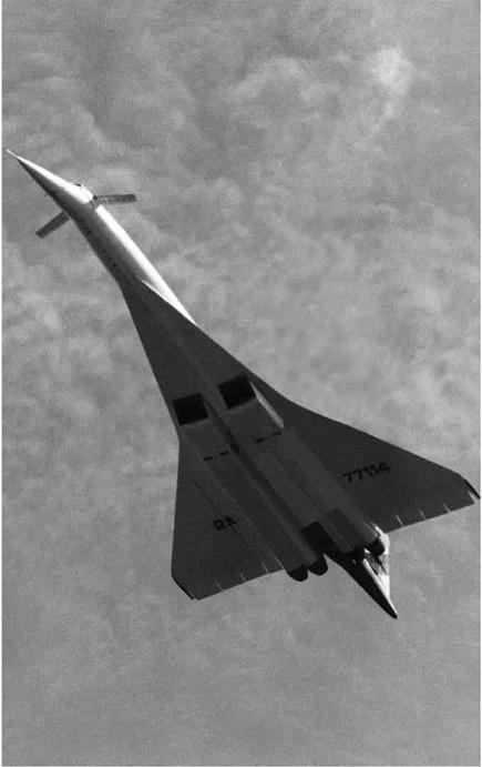
Another flight research program devoted to SCR included a post-Cold War cooperative venture with Russia’s Central Institute of Aerohydromechanics (TsAGI) to resurrect and fly the Tu-144 SST of the 1970s.[1110] Equipped with new engines with more powerful turbofans, the Tu-144LL (the modified designation reflecting the Cyrillic abbreviation for flying laboratory) flew a 2-phase, 26-flight-test program in 1998 and 1999 at cruise Mach numbers to 2.15. All the flights were flown from Zhukovsky Flight Research Center outside Moscow, and NASA pilots flew on 3 of the sorties.[1111] Experiments investigated handling qualities, boundary layer characteristics, ground cushion effects of the large delta wing, cabin aerodynamic noise, and sideline engine noise.

Подпись: NASA F-16XL modified for Supersonic Laminar Flow Control program. The right wing is the normal arrow wing configuration, while the left wing has the LFC glove extending from the fuselage to the mid-span sweep "kink.” NASA. Подпись: 10

Another flight research program of the 1990s was the NASA use of the arrow wing F-16XL. Flown over 13 months in 1995-1996, the 90-hour, 45-flight-test program was known as the Supersonic Laminar Flow Control program.[1112] A glove was fitted over the left wing of the air­craft, which had millions of microscopic laser-drilled holes. A suction system drew the turbulent supersonic boundary layer through the holes to attempt to create a laminar boundary layer with less friction drag. Flight Mach numbers up to Mach 2 showed that the concept was indeed effective at creating laminar flow. This was a significant finding for an HSCT, for which drag reduction at cruise conditions is so critical.[1113]

The USAF had taken the SR-71 fleet out of service in 1990 because of cost concerns and opinions that its reconnaissance mission could be
better accomplished by other platforms, including satellites. This freed a number of Mach 3 cruise platforms equipped with advanced digital control systems for possible use by NASA in the SCR effort. Dryden Flight Research Center was allocated two SR-71As for research use and the sole SR-71B airframe for pilot checkout training. The crew­training simulator was also installed at Dryden. It was being updated to new computer technology when the financial ax fell yet again. Some research relevant to supersonic cruise was performed on the SR-71s. Handling qualities and cruise performance using the updated config­uration were evaluated. Despite the digital system, the use of an iner­tial vertical velocity indicator at Mach 3 was still found to be superior to the air-data-driven vertical velocity for precise altitude control.[1114] An experimental air-data system using lasers to sense angle of attack and sideslip rather than differential air pressure was also tested to confirm that it would function at the 80,000-foot cruise altitude. Several Sonic Boom Research Program flights were flown, as mentioned earlier, for in-flight sonic boom shock wave measurements. The SR-71 had to slow and descend from its normal cruise levels to accommodate the instru­mented chase aircraft. Like the YF-12, the SR-71 was again used as a platform for experiments. Several devices planned for satellite Earth observations were carried in the sensor bays of the SR-71 for observa­tions from above 95 percent of the Earth’s atmosphere. An ultraviolet camera funded by the Jet Propulsion Laboratory conducted celestial observations from the same vantage point.

Подпись: 10The program that mainly funded retention of the airplanes was actu­ally in support of a proposed (later canceled) reuseable space launch vehicle, the Lockheed-Martin X-33. It would employ a revolutionary rocket engine, the Linear Aerospike Rocket Engine (LASRE). The engine used shock waves to contain the exhaust and increase thrust at a com­paratively light structural weight. For risk reduction, the SR-71 would have a fixture mounted atop the fuselage, on which would be installed a 12-percent model of the X-33 with engine for aerial tests. The fixture was installed, but the increased drag of the fixture plus the LASRE limited the maximum Mach number attainable to around Mach 2. The instal­lation was carried on several flights, but insuperable flight safety issues

meant that the engine never was fired on the aircraft.[1115] Funding ended with the demise of the SCR program. The final flight of the world’s only Mach 3 supersonic cruise fleet occurred as an overflight of the Edwards Air Force Base Open House on October 9, 1999. The staff of the Russian Test Pilot School furnished an indication of the unique cachet of the air­craft when they visited the USAF Test Pilot School at Edwards as part of a reciprocal exchange in the mid-1990s. They had earlier hosted the Americans in Moscow and allowed them to fly current Russian fighters. When asked what they would like to fly at Edwards, the response was the SR-71. T hey were told that was unfortunately impossible because of cost and because the SR was a NASA asset, but that a simulator flight might be arranged. Even so, these experienced test pilots welcomed the opportunity to sample the SR-71 simulator.

Подпись: 10By 1999, much research work had been performed in support of the HSCT.[1116] Nevertheless, no breakthrough seemed to have been made that answered all the issues raised on a practical HSCT development deci­sion. One of the major contractor contributors had been McDonnell – Douglas, which became Boeing in the defense industry implosion of the 1990s.[1117] In 1999, Boeing withdrew further major financial support, as it saw no possibility of an HSCT before 2020. Also in 1999, NASA Administrator Daniel S. Goldin cut $600 million from the aeronautics budget to provide support for the International Space Station. These two actions essentially ended the SCR for the time being.

Predicting an Icy Future

Подпись: 12With its years of accumulated research about all aspects of icing—i. e., weather conditions that produce it, types of ice that form under vari­ous conditions, de-icing and anti-icing measures and when to employ them—NASA’s data would be useless unless they were somehow pack­aged and made available to the aviation community in a convenient manner so that safety could be improved on a daily basis. And so with desktop computers becoming more affordable, available, and increas­ingly powerful enough to crunch fairly complex datasets, in 1983, NASA researchers at what was still named the Lewis Research Center began developing a computer program that would at first aid NASA’s in-house researchers, but would grow to become a tool that would aid pilots, air traffic controllers, and any other interested party in the flight plan­ning process through potential areas of icing. The software was dubbed LEWICE, and version 0.1 originated in 1983 as a research code for in­house use only. As of the beginning of 2010, version 2.0 is the official cur­rent version, although a version 3.2.2 is in development, as is the first 0.1 version of GlennICE, which is intended to accurately predict ice growth under any weather conditions for any aircraft surface.[1243]

LEWICE, which spelled out is the Lewis Ice Accretion Program, is a freely available desktop software program used by hundreds of people in the aviation community for purposes of predicting the amount, type, and shape of ice an aircraft might experience given a particular weather forecast, as well as what kind of anti-icing heat requirements may be necessary to prevent any buildup of ice from beginning. The software

runs on a desktop PC and provides its analysis of the input data within minutes, fast enough that the user can try out some different numbers to get a range of possible icing experiences in flight. All of the predic­tions are based on extensive research and real-life observations of icing collected through the years both in flight and in icing wind tunnel tests.[1244]

Подпись: 12At its heart, LEWICE attempts to predict how ice will grow on an aircraft surface by evaluating the thermodynamics of the freezing pro­cess that occurs when supercooled droplets of moisture strike an air­craft in flight. Variables considered include the atmospheric parameters of temperature, pressure, and velocity, while meteorological parame­ters of liquid water content, droplet diameter, and relative humidity are used to determine the shape of the ice accretion. Meanwhile, the aircraft surface geometry is defined by segments joining a set of dis­crete body coordinates. All of that data are crunched by the software in four major modules that result in a flow field calculation, a parti­cle trajectory and impingement calculation, a thermodynamic and ice growth calculation, and an allowance for changes in the aircraft geom­etry because of the ice growth. In processing the data, LEWICE applies a time-stepping procedure that runs through the calculations repeat­edly to "grow” the ice. Initially, the flow field and droplet impingement characteristics are determined for the bare aircraft surface. Then the rate of ice growth on each surface segment is determined by applying the thermodynamic model. Depending on the desired time increment, the resulting ice growth is calculated, and the shape of the aircraft sur­face is adjusted accordingly. Then the process repeats and continues to predict the total ice expected based on the time the aircraft is flying through icing conditions.[1245]

The basic functions of LEWICE essentially account for the capa­bilities of the software up through version 1.6. Version 2.0 was the next release, and although it did not change the fundamental process or mod­els involved in calculating ice accretion, it vastly improved the robust­ness and accuracy of the software. The current version was extensively tested on different computer platforms to ensure identical results and also incorporated the very latest and complete datasets based on the most
recent research available, while also having its prediction results ver­ified in controlled laboratory tests using the Glenn IRT. Version 3.2— not yet released to date—will add the ability to account for the presence and use of anti-icing and de-icing systems in determining the amount, shape, and potential hazard of ice accretion in flight. Previously these variables could be calculated by reading LEWICE output files into other software such as ANTICE 1.0 or LEWICE/Thermal 1.6.[1246]

Подпись: 12According to Jaiwon Shin, the current NASA Associate Administrator for the Aeronautics Research Mission Directorate, the LEWICE software is the most significant contribution NASA has made and continues to make to the aviation industry in terms of the topic of icing accretion. Shin said LEWICE continues to be used by the aviation community to improve safety, has helped save lives, and is an incredibly useful tool in the classroom to help teach future pilots, aeronautical engineers, traf­fic controllers, and even meteorologists about the icing phenomenon.[1247]

Relaxed Stability Meets High Alpha: The F-16 Program

Подпись: 13Initially envisioned as a nimble lightweight fighter with "carefree” maneu­verability, the F-16 was designed from the onset with reliance on the flight control system to ensure satisfactory behavior at high-angle-of – attack conditions.[1298] By using the concept of relaxed longitudinal sta­bility, the configuration places stringent demands on the flight control system. In addition to extensive static and dynamic wind tunnel testing in Langley’s tunnels from subsonic to supersonic speeds and free-flight model studies for high-angle-of-attack conditions and spinning, Langley and its partners from General Dynamics and the Air Force conducted in-depth piloted studies in a Langley simulator. The primary objective of the studies was to assess the ability of the F-16 control system to prevent loss of control and departures for critical dynamic maneuvers involving rapid roll rates at high angles of attack and low airspeeds.[1299] General Dynamics used the results of the study to modify gains in the F-16 flight control system and introduce new elements for enhanced departure prevention in production aircraft.

One of the more significant events in NASA’s support of the F-16 was the timely identification and solution to a potentially unrecoverable "deep-stall” condition. Analysis of Langley wind tunnel data at extreme angles of attack (approaching 90 degrees) and simulated maneuvers by pilots in the DMS during the earlier YF-16 program indicated that rapid roll maneuvers at high angles of attack could saturate the nose-down aerodynamic control capability of the flight control system, resulting in the inherently unstable airplane pitching up to an extreme angle of attack with insufficient nose-down aerodynamic control to recover to normal flight.[1300] The ability of the YF-16 to enter this dangerous condi­tion was demonstrated to General Dynamics and the Air Force, but aero­dynamic data obtained in other NASA and industry wind tunnel tests of different YF-16 models did not indicate the existence of such a problem.

The scope of the ensuing YF-16 flight program was limited and did not allow for exploration of a potential deep-stall problem.

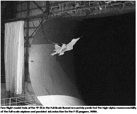
Подпись: 13The early production F-16 configuration also indicated a deep-stall issue during Langley tests in the Full-Scale Tunnel, and once again, the data contradicted results from other wind tunnels. As a result, the Langley data were dismissed as contaminated with "scale effects,” and concerns over the potential existence of a deep stall were minimal as the aircraft entered flight-testing at Edwards Air Force Base. However, dur­ing zoom climbs with combined rolling motions, the specially equipped F-16 high-angle-of-attack test airplane entered a stabilized deep-stall condition, and after finding no effective control for recovery, the pilot was forced to use the emergency spin recovery parachute to recover the aircraft to normal flight. The motions and flight variables were virtually identical to the Langley predictions.

Because Langley’s aerodynamic model of the F-16 provided the most realistic inputs for the incident, a joint NASA, General Dynamics, and Air Force team aggressively used the DMS simulator at Langley to develop a piloting strategy for recovery from the deep stall. Under Langley’s leadership, the team conceived a "pitch rocker” technique, in which the pilot pumped the control stick fore and aft to set up oscillatory pitching motions that broke the stabilized deep-stall condition and allowed the aircraft to return to normal flight. The concept was demonstrated dur­ing F-16 flight evaluations and was incorporated in the early flight con­trol systems as a pilot-selectable emergency mode. Ultimately, the deep stall was eliminated by an increase in size of the horizontal tail (which was done for other reasons) on later production models of the F-16.

The value of Langley’s support in the area of high-angle-of-attack behavior for the F-16 represented the first step for advancing method­ology for fly-by-wire control systems with special capabilities for severe maneuvers at high angles of attack. The experience demonstrated the advantages of NASA’s involvement as a Government partner in develop­ment programs and the value of having NASA facilities, technical exper­tise, and experience available to design teams in a timely manner. The initial objective of carefree maneuverability for the F-16 was provided in a very effective manner by the NASA-industry-DOD team.

Vectored V/STOL Comes of Age: The P. 1127, Kestrel, and YAV-8B VSRA

In 1957, Britain’s Hawker and Bristol firms began development of what would prove to be the most revolutionary V/STOL airplane developed to that point in aviation history, the P.1127. This aircraft program, begun

Подпись: The Hawker P.1127 during early hovering trials. NASA. Подпись: 14

as a private development by two of Britain’s more respected companies, was the product of Sir Sidney Camm and Ralph Hooper of Hawker, and Stanley Hooker of Bristol. It eventually spawned a remarkable opera­tional aircraft that fought in multiple wars and served in the air forces and naval air services of many nations. Hawker had an enviable reputa­tion for designing high-performance aircraft, dating to the Sopwith fight­ers of the First World War, and Bristol had an equally impressive one in the field of aircraft propulsion. NATO’s Mutual Weapon Development Project (MWDP) supported the project as it evolved, and it drew heav­ily upon American support from John Stack of NASA and the Langley Research Center, and from the U. S. Marine Corps. (The P.1127 design was extensively tested in Langley’s 30-Foot by 60-Foot Full Scale Tunnel, and the 16-Foot Transonic Tunnel, helping identify and alleviate a poten­tially serious pitch-up problem exacerbated by power effects during tran­sition upon the original horizontal tail configuration).[1446] Powered by a

single Bristol Siddeley Pegasus 5 vectored-thrust turbofan of 15,000- pound thrust, the P.1127 completed its first tethered hover in October 1960, an untethered hover the next month, and, after extensive prepara­tion, its first transition from vertical to conventional in September 1961. As with the X-14 and other V/STOL testbeds, bleed air reaction nozzles were used for hover attitude control and, in the P.1127’s initial configu­ration, had no SAS. Low control power, aerodynamic suck-down, and marginal altitude control power made for a high pilot workload for this early Harrier predecessor. Even so, NACA researchers quickly realized that the P.1127 offered remarkable promise. NASA pilots Jack Reeder from Langley and Fred Drinkwater from Ames went to Europe to fly the P.1127 in June 1962, Reeder confiding afterward: "The British are ahead of us again.”[1447] His flight evaluation report noted:

Подпись: 14The P. 1127 is not a testbed aircraft in the usual sense. It is advanced well beyond this stage and is actually an operational prototype, with which it is now possible to study the VSTOL concept in relation to military requirements by actual opera­tion in the field. The aircraft is easily controlled and has safe flight characteristics throughout the range from hover to air­plane flight. The performance range is very great; yet, conver­sions to or from low or vertical flight can be accomplished simply, quickly, and repeatedly.[1448]

Camm’s P.1127 led to the Hawker Kestrel F. G.A. Mk. 1, an interim "militarized” variant, nine of which undertook operational suitabil­ity trials with a NATO tripartite (U. K., U. S., and Federal Republic of Germany) evaluation squadron in 1965. The trials confirmed not only the basic performance of the aircraft, but also its military potential. So the Kestrel, in turn, led directly to a production military derivative, the Hawker Harrier G. R. Mk. 1—or, as known in U. S. Marine Corps service, the AV-8A. Eight of the Kestrel aircraft, designated XV-6A, remained in the United States for follow-on testing. NASA received two Kestrels, flying them in an extensive evaluation program at Langley with pilots

Jack Reeder, Lee H. Person, Jr., Robert Champine, and Perry L. Deal, under the supervision of project engineer Richard Culpepper.[1449]

Подпись: 14Langley tunnel-testing and flight-testing revealed a number of defi­ciencies, though not of such magnitude as to detract from the impres­sion that the P.1127 was a remarkable accomplishment, and that it had tremendous potential for development. For example, a directional insta­bility was noticed in turning out of the wind, yaw control power was low but not considered unsafe, and pitch-trim changes occurred when leav­ing ground effect. The usual hot-gas ingestion problem could be circum­vented by maintaining a low forward speed in takeoff and landing. A static pitch instability was encountered at alphas greater than approxi­mately 15 degrees, and a large positive dihedral effect limited crosswind operations. Transition characteristics were outstanding, with only small trim changes required. Overall, low – and high-speed performance was excellent. Like any swept wing airplane, the Kestrel’s "Dutch roll” lateral – directional damping was low at altitude, requiring provision of a yaw damper. It had good STOL performance when the engine nozzles were deflected between purely vertical and purely horizontal settings. Indeed, this would later become one of the Harrier strike fighter’s strongest oper­ational qualities.[1450]

Like any operational aircraft, the Harrier went through progressive refinement. Its evolution coincided with the onset of advanced avionics, the emergence of composite structures, and NASA’s development of the supercritical wing. All were developments incorporated in the next gener­ation of Harrier, the AV-8B Harrier II, developed at the behest of the U. S

Marine Corps and adopted, in slightly different form, as the Harrier Mk. 5 by the Royal Air Force. As well, the AV-8B benefited from Langley research on optimum positioning of engine nozzles, trailing-edge flaps, and the wing, in order to obtain higher propulsive lift. (This jet age work mirrored much earlier work on optimum positioning of propellers, engines, and nacelles undertaken at Langley in the 1920s by the NACA).[1451]

Подпись: 14Two AV-8A Harriers had been modified to serve as prototypes of the new Harrier II, these being designated YAV-8B. Though deceptively similar to the earlier AV-8A, the YAV-8B relied extensively on graphite epoxy composite structure and had a leading-edge extension at its wing – root and a bigger, supercritical wing. The first made its initial flight in November 1978, joined shortly afterward by the second. A year later, in November 1979, the second YAV-8B crashed after engine failure; its pilot ejected safely. However, flight-testing by contractor and service pilots confirmed that the AV-8B would constitute a significant advance over the earlier AV-8A for, during its evaluation program, "all performance requirements were met or exceeded.”[1452] Not surprisingly, the AV-8B entered production and squadron service with the U. S. Marine Corps, replacing the older Vietnam-legacy AV-8A.

In 1984, after the AV-8B entered operational service, the U. S. Marine Corps delivered the surviving YAV-8B to Ames so that Ames researchers could investigate advanced controls and flight displays, such as those that might be incorporated on future V/STOL combat systems called upon to conduct vertical envelopment assaults from small assault car­riers and other vessels in all-weather conditions. The study effort that followed built upon Ames’s legacy of V/STOL simulation studies, using both ground and flight simulators to evaluate a variety of guidance, con­trol, and display concepts, particularly the research of Vernon K. Merrick, Ernesto Moralez, III, Jeffrey A. Schroeder, and their associates.[1453] NASA designated the YAV-8B the V/STOL Systems Research Aircraft (VSRA). A team led by Del Watson and John D. Foster modifying it with digi­tal fly-by-wire controls for pitch, roll, yaw, thrust magnitude and thrust deflection, and programmable electronic head-up displays. Researchers subsequently flew the YAV-8B in an extensive evaluation of control

Подпись: 14
Vectored V/STOL Comes of Age: The P. 1127, Kestrel, and YAV-8B VSRA

The NASA Ames YAV-8B V/STOL Systems Research Aircraft. NASA.

system concepts and behavior, from decelerations to hover, and then from hover to a vertical landing, assessing flying qualities tradeoffs for each of the various control concepts studied and evaluating advanced guidance and navigation displays as well.[1454] In addition to NASA pilots, a range of Marine, Royal Air Force, McDonnell-Douglas, and Rolls-Royce test pilots flew the aircraft. Their inputs, combined with data from Ames’s Vertical Motion Simulator, helped researcher Jack Franklin develop flying qualities criteria and control system and display concepts sup­porting the Joint Strike Fighter program.[1455] With the conclusion of the

VSRA aircraft program in 1997, NASA Ames’s role in V/STOL research came to an end.

Подпись: 14In conclusion, in spite of the many challenges revealed in these summaries of V/STOL aircraft, the information accumulated from the design, development, and flight evaluations has provided a useful data­base for V/STOL designs. It is of interest to note that even though most of the aircraft were deficient, to some degree, in terms of aerodynamics, propulsion systems, or performance, it was always possible to develop special operating techniques to circumvent these problems. For the most part, this review would indicate that performance and handling – qualities limitations severely restricted operational evaluations for all types of V/STOL concepts. It has become quite obvious that V/STOL air­craft must be designed with good STOL performance capability to be cost-effective, a virtue not shared by many of the aircraft researched by NASA. Further, flight experience has shown that good handling quali­ties are needed, not only in the interest of safety, but also to permit the aircraft to carry out its mission in a cost-effective manner. It was appar­ent also that SAS was required to some degree for safely carrying out even simple operational tasks. The question of how much control sys­tem complexity is needed for various tasks and missions is still unan­swered. Another area deserving of increased attention derives from the fact that most of the V/STOL aircraft studied suffered to some degree from adverse ground effects. In this regard, better prediction techniques are needed to avoid costly aircraft modifications or restricted opera­tional use. Finally, there is an important continued need for good test­ing techniques and facilities to ensure satisfactory performance and control before and during flight-testing.

Today, NASA’s investment in V/STOL technology promises to be a key enabling technology in making the airspace system more environmen­tally friendly and efficient. Cruise Efficient Short Take-Off and Landing Aircraft (CESTOL) and Civil Tilt Rotor (CTR) promise to expand the number of takeoff and landing locations, operating in terminal areas in a simultaneous noninterfering manner (SNI) with conventional traffic, relieving overtaxed hub airports. CESTOL-CTR aircraft avoid the air­space and runways required by commercial aircraft using steeply curved approach and departure paths, thus enabling greater system capacity, reducing delays, and saving fuel. To fulfill this vision, performance penal­ties associated with STOL capability requires continued NASA research
to mitigate.[1456] While much still remains to be accomplished, much has already been achieved, and the vision of future V/STOL remains vibrant and exciting. That it is constitutes an accolade to those men and women of NASA, and the NACA before, whose contributions made V/STOL air­craft a practical reality.

Подпись: 14

Taming Microburst: NASA’s Wind Shear Research Effort Takes Wing

The Dallas crash profoundly accelerated NASA and FAA wind shear research efforts. Two weeks after the accident, responding to calls from concerned constituents, Representative George Brown of California requested a NASA presentation on wind shear and subsequently made a fact-finding visit to the Langley Research Center. Dr. Jeremiah F. Creedon, head of the Langley Flight Systems Directorate, briefed the Congressman on the wind shear problem and potential technologies that might allevi­ate it. Creedon informed Brown that Langley researchers were running a series of modest microburst and wind shear modeling projects, and that an FAA manager, George "Cliff” Hay, and NASA Langley research engineer Roland L. Bowles had a plan underway for a comprehensive airborne wind shear detection research program. During the briefing, Brown asked how much money it would take; Creedon estimated several million dollars. Brown remarked the amount was "nothing”; Creedon
replied tellingly, "It’s a lot of money if you don’t have it.” As the Brown party left the briefing, one of his aides confided to a Langley manager "NASA [has] just gotten itself a wind shear program.” The combination of media attention, public concern, and congressional interest triggered the development of "a substantial, coordinated interagency research effort to address the wind shear problem.”[64]

Taming Microburst: NASA's Wind Shear Research Effort Takes WingOn July 24, 1986, NASA and the FAA mandated the National Integrated Windshear Plan, an umbrella project overseeing several initiatives at different agencies.[65] The joint effort responded both to congressional directives and National Transportation Safety Board recommendations after documentation of the numerous recent wind shear accidents. NASA Langley Research Center’s Roland L. Bowles subsequently oversaw a rigorous plan of wind shear research called the Airborne Wind Shear Detection and Avoidance Program (AWDAP), which included the development of onboard sensors and pilot train­ing. Building upon earlier supercomputer modeling studies by Michael L. Kaplan, Fred H. Proctor, and others, NASA researchers devel­oped the Terminal Area Simulation System (TASS), which took into con­sideration a variety of storm parameters and characteristics, enabling numerical simulation of microburst formation. Out of this came data that the FAA was able to use to build standards for the certifica­tion of airborne wind shear sensors. As well, the FAA created a flight

safety program that supported NASA development of wind shear detection technologies.[66]

Taming Microburst: NASA's Wind Shear Research Effort Takes WingAt NASA Langley, the comprehensive wind shear studies started with laboratory analysis and continued into simulation and flight eval­uation. Some of the sensor systems that Langley tested work better in rain, while others performed more successfully in dry conditions.[67] Most were tested using Langley’s modified Boeing 737 systems testbed.[68] This research airplane studied not only microburst and wind shear with the Airborne Windshear Research Program, but also tested electronic and computerized control displays ("glass cockpits” and Synthetic Vision Systems) in development, microwave landing systems in development, and Global Positioning System (GPS) navigation.[69]

NASA’s Airborne Windshear Research Program did not completely resolve the problem of wind shear, but "its investigation of microburst detection systems helped lead to the development of onboard monitor­ing systems that offered airliners another way to avoid potentially lethal situations.”[70] The program achieved much and gave confidence to those pursuing practical applications. The program had three major goals. The first was to find a way to characterize the wind shear threat in a way that would indicate the hazard level that threatened aircraft. The second was to develop airborne remote-sensor technology to provide accurate, forward­looking wind shear detection. The third was to design flight management systems and concepts to transfer this information to pilots in such a way that they could effectively respond to a wind shear threat. The program had to pursue these goals under tight time constraints.[71] Time was of the essence, partly because the public had demanded a solution to the scourge of microburst wind shear and because a proposed FAA regulation stipu­lated that any "forward-looking” (predictive) wind shear detection tech­nology produced by NASA be swiftly transferred to the airlines.

An airborne technology giving pilots advanced warning of wind shear would allow them the time to increase engine power, "clean up”
the aircraft aerodynamically, increase penetration speed, and level the airplane before entering a microburst, so that the pilot would have more energy, altitude, and speed to work with or to maneuver around the microburst completely. But many doubted that a system incorporating all of these concepts could be perfected. The technologies offering most potential were microwave Doppler radar, Doppler Light Detecting and Ranging (LIDAR, a laser-based system), and passive infrared radiome – try systems. However, all these forward-looking technologies were chal­lenging. Consequently, developing and exploiting them took a minimum of several years. At Langley, versions of the different detection systems were "flown” as simulations against computer models, which re-created past wind shear accidents. However, computer simulations could only go so far; the new sensors had to be tested in actual wind shear condi­tions. Accordingly, the FAA and NASA expanded their 1986 memoran­dum of understanding in May 1990 to support flight research evaluating the efficacy of the advanced wind shear detection systems integrating airborne and ground-based wind shear measurement methodologies. Researchers swiftly discovered that pilots needed as much as 20 sec­onds of advance warning if they were to avert or survive an encounter with microburst wind shear.[72]

Taming Microburst: NASA's Wind Shear Research Effort Takes WingKey to developing a practical warning system was deriving a suit­able means of assessing the level of threat that pilots would face, because this would influence the necessary course of action to avoid potential disaster. Fortunately, NASA Project Manager Roland Bowles devised a hazard index called the "F-Factor.” The F-Factor, as ultimately refined by Bowles and his colleagues Michael Lewis and David Hinton, indi­cated how much specific excess thrust an airplane would require to fly through wind shear without losing altitude or airspeed.[73] For instance, a typical twin-engine jet transport plane might have engines capable

of producing 0.17 excess thrust on the F-Factor scale. If a microburst wind shear registered higher than 0.17, the airplane would not be able to fly through it without losing airspeed or altitude. The F-Factor pro­vided a way for information from any kind of sensor to reach the pilot in an easily recognizable form. The technology also had to locate the position and track the movement of dangerous air masses and provide information on the wind shear’s proximity and volume.[74] Doppler-based wind shear sensors could only measure the first term in the F-Factor equation (the rate of change of horizontal wind). This limitation could result in underestimation of the hazard. Luckily, there were several ways to measure changes in vertical wind from radial wind measurements, using equations and algorithms that were computerized. Although error ranges in the device’s measurement of the F-Factor could not be elim­inated, these were taken into account when producing the airborne system.[75] The Bowles team derivation and refinement of the F-Factor constituted a major element of NASA’s wind shear research, to some, "the key contribution of NASA in the taming of the wind-shear threat.” The FAA recognized its significance by incorporating F-Factor in its regulations, directing that at F-Factors of 0.13 or greater, wind shear warnings must be issued.[76]

Taming Microburst: NASA's Wind Shear Research Effort Takes WingIn 1988, NASA and researchers from Clemson University worked on new ways to eliminate clutter (or data not related to wind shear) from information received via Doppler and other kinds of radar used on an airborne platform. Such methods, including antenna steering and adap­tive filtering, were somewhat different from those used to eliminate clut­ter from information received on a ground-based platform. This was

because the airborne environment had unique problems, such as large clutter-to-signal ratios, ever-changing range requirements, and lack of repeatability.[77]

Taming Microburst: NASA's Wind Shear Research Effort Takes WingThe accidents of the 1970s and 1980s stimulated research on a vari­ety of wind shear predictive technologies and methodologies. Langley’s success in pursuing both enabled the FAA to decree in 1988 that all commercial airline carriers were required to install wind shear detec­tion devices by the end of 1993. Most airlines decided to go with reactive systems, which detect the presence of wind shear once the plane has already flown into it. For American, Northwest, and Continental— three airlines already testing predictive systems capable of detecting wind shear before an aircraft flew into it—the FAA extended its deadline to 1995, to permit refinement and certification of these more demand­ing and potentially more valuable sensors.[78]

From 1990 onwards, NASA wind shear researchers were partic­ularly energetic, publishing and presenting widely, and distributing technical papers throughout the aerospace community. Working with the FAA, they organized and sponsored well-attended wind shear con­ferences that drew together other researchers, aviation administrators, and—very importantly—airline pilots and air traffic controllers. Finally, cognizant of the pressing need to transfer the science and technology of wind shear research out of the laboratory and onto the flight line, NASA and the FAA invited potential manufacturers to work with the agencies in pursuing wind shear detector development.[79]

The invitations were welcomed by industry. Three important avionics manufacturers—Allied Signal, Westinghouse, and Rockwell Collins—sent engineering teams to Langley. These teams followed NASA’s wind shear effort closely, using the Agency’s wind shear simulations to enhance the capabilities of their various systems. In 1990, Lockheed introduced its Coherent LIDAR Airborne Shear Sensor (CLASS), developed under con­tract to NASA Langley. CLASS was a predictive system allowing pilots to avoid hazards of low-altitude wind shear under all weather conditions. CLASS would detect thunderstorm downburst early in its development
and emphasize avoidance rather than recovery. After consultation with airline and military pilots, Lockheed engineers decided that the system should have a 2- to 4-kilometer range and should provide a warning time of 20 to 40 seconds. A secondary purpose of the system would be to provide predictive warnings of clear air turbulence. In conjunction with NASA, Lockheed conducted a 1-year flight evaluation program on Langley’s 737 during the following year to measure line-of-sight wind velocities from many wind fields, evaluating this against data obtained via air – and ground-based radars and accelerometer-based systems and thus acquiring a comparative database.[80]

Taming Microburst: NASA's Wind Shear Research Effort Takes WingAlso in 1990, using technologies developed by NASA, Turbulence Prediction Systems of Boulder, CO, successfully tested its Advance Warning Airborne System (AWAS) on a modified Cessna Citation small, twin-jet research aircraft operated by the University of North Dakota. Technicians loaded AWAS into the luggage compartment in front of the pilot. Pilots intentionally flew the plane into numerous wind shear events over the course of 66 flights, including several wet microbursts in Orlando, FL, and a few dry microbursts in Denver. On the Cessna, AWAS measured the thermal characteristics of microbursts to predict their pres­ence during takeoff and landing. In 1991, AWAS units were flown aboard three American Airlines MD-80s and three Northwest Airlines DC-9s to study and improve the system’s nuisance alert response. Technicians also installed a Honeywell Windshear Computer in the planes, which Honeywell had developed in light of NASA research. The computer processed the data gathered by AWAS via external aircraft measuring instruments. AWAS also flew aboard the NASA Boeing 737 during sum­mer 1991. Unfortunately, results from these research flights were not conclusive, in part because NASA conducted research flights outside AWAS’s normal operating envelope, and in an attempt to compensate for differences in airspeed, NASA personnel sometimes overrode automatic features. These complications did not stop the develop­ment of more sophisticated versions of the system and ultimate FAA certification.[81]

After analyzing data from the Dallas and Denver accidents, Honeywell researchers had concluded that temperature lapse rate, or the drop in temperature with the increase in altitude, could indicate wind shear caused by both wet and dry microbursts. Lapse rate could not, of course, communicate whether air acceleration was horizontal or verti­cal. Nonetheless, this lapse rate could be used to make reactive systems more "intelligent,” "hence providing added assurance that a danger­ous shear has occurred.” Because convective activity was often associ­ated with turbulence, the lapse rate measurements could also be useful in warning of impending "rough air.” Out of this work evolved the first – generation Honeywell Windshear Detection and Guidance System, which gained wide acceptance.[82]

Taming Microburst: NASA's Wind Shear Research Effort Takes WingSupporting its own research activities and the larger goal of air safety awareness, NASA developed a thorough wind shear training and famil­iarization program for pilots and other interested parties. Flightcrews "flew” hundreds of simulated wind shears. Crews and test personnel flew rehearsal flights for 2 weeks in the Langley and Wallops areas before deploying to Orlando or Colorado for actual in-flight microburst encoun­ters in 1991 and 1992.

The NASA Langley team tested three airborne systems to predict wind shear. In the creation of these systems, it was often assisted by technology application experts from the Research Triangle Institute of Triangle Park, NC.[83] The first system tested was a Langley-sponsored Doppler microwave radar, whose development was overseen by Langley’s Emedio "Brac” Bracalente and the Langley Airborne Radar Development Group. It sent a microwave radar signal ahead of the plane to detect raindrops and other moisture in the air. The returning signal provided information on the motion of raindrops and moisture particles, and it translated this information into wind speed. Microwave radar was best in damp or wet conditions, though not in dry conditions. Rockwell International’s Collins Air Transport Division in Cedar Rapids, IA, made the radar transmitter, extrapolated from the standard Collins 708 weather radar. NASA’s Langley Research Center in Hampton, VA, developed
the receiver/detector subsystem and the signal-processing algorithms and hardware for the wind shear application. So enthusiastic and confident were the members of the Doppler microwave test team that they designed their own flight suit patch, styling themselves the "Burst Busters,” with an international slash-and-circle "stop” sign overlaying a schematic of a microburst.[84]

Taming Microburst: NASA's Wind Shear Research Effort Takes WingThe second system was a Doppler LIDAR. Unlike radio beam – transmitting radar, LIDAR used a laser, reflecting energy from aerosol particles rather than from water droplets. This system had fewer prob­lems with ground clutter (interference) than Doppler radar did, but it did not work as well as the microwave system does in heavy rain. The system was made by the Lockheed Corporation’s Missiles and Space Company in Sunnyvale, CA; United Technologies Optical Systems, Inc., in West Palm Beach, FL; and Lassen Research of Chico, CA.[85] Researchers noted that an "inherent limitation” of the radar and LIDAR systems was their inability to measure any velocities running perpendicular to the system’s line of sight. A microburst’s presence could be detected by measuring changes in the horizontal velocity profile, but the inability to measure a perpendicular downdraft could result in an underestimation of the magnitude of the hazard, including its spatial size.[86]

The third plane-based system used an infrared detector to find tem­perature changes in the airspace in front of the plane. It monitored carbon dioxide’s thermal signatures to find cool columns of air, which often indicate microbursts. The system was less expensive and less com­plex than the others but also less precise, because it could not directly measure wind speed.[87]

Taming Microburst: NASA's Wind Shear Research Effort Takes Wing
NASA 51 5, the Langley Boeing 737, on the airport ramp at Orlando, FL, during wind shear sensor testing. NASA.

CASE #2-37: 06/20/91 ORLANDO MICROBURST

VELOCITY VECTORS AT 50 M AGL

Taming Microburst: NASA's Wind Shear Research Effort Takes Wing

Taming Microburst: NASA's Wind Shear Research Effort Takes Wing

A June 1991 radar plot of a wind shear at Orlando, showing the classic radial outflow. This one is approximately 5 miles in diameter. NASA.

Taming Microburst: NASA's Wind Shear Research Effort Takes WingIn 1990-1992, Langley’s wind shear research team accumulated and evaluated data from 130 sensor-evaluation research flights made using the Center’s 737 testbed. [88] Flight-test crews flew research missions in the Langley local area, Philadelphia, Orlando, and Denver. Risk mitiga­tion was an important program requirement. Thus, wind shear investi­gation flights were flown at higher speeds than airliners typically flew, so that the 737 crew would have better opportunity to evade any hazard it encountered. As well, preflight ground rules stipulated that no penetra­tions be made into conditions with an F-Factor greater than 0.15. Of all the systems tested, the airborne radar functioned best. Data were accu­mulated during 156 weather runs: 109 in the turbulence-prone Orlando area. The 737 made 15 penetrations of microbursts at altitudes ranging from 800 to 1,100 feet. During the tests, the team evaluated the radar at various tilt angles to assess any impact from ground clutter (a common problem in airborne radar clarity) upon the fidelity of the airborne sys­tem. Aircraft entry speed into the microburst threat region had little effect on clutter suppression. All together, the airborne Doppler radar tests col­lected data from approximately 30 microbursts, as well as 20 gust fronts, with every microburst detected by the airborne radar. F-Factors measured with the airborne radar showed "excellent agreement” with the F-Factors measured by Terminal Doppler Weather Radar (TDWR), and comparison of airborne and TDWR data likewise indicated "comparable results.”[89] As Joseph Chambers noted subsequently, "The results of the test program demonstrated that Doppler radar systems offered the greatest promise for early introduction to airline service. The Langley forward-looking Doppler radar detected wind shear consistently and at longer ranges than other systems, and it was able to provide 20 to 40 seconds warning of upcoming microburst.”[90] The Burst Busters clearly had succeeded. Afterward, forward-looking Doppler radar was adopted by most airlines.

Taming Microburst: NASA's Wind Shear Research Effort Takes Wing

NASA Langley’s wind shear team at Orlando in the cockpit of NASA 515. Left to right: Program Manager Roland Bowles, research pilot Lee Person, Deputy Program Manager Michael Lewis, research engineer David Hinton, and research engineer Emedio Bracalente. Note Bracalente’s "Burst Buster” shoulder patch. NASA.

Aviation Safety Reporting System: 1975

On December 1, 1974, a Trans World Airlines (TWA) Boeing 727, on final approach to Dulles airport in gusty winds and snow, crashed into a Virginia mountain, killing all aboard. Confusion about the approach to the airport, the navigation charts the pilots were using, and the instruc­tions from air traffic controllers all contributed to the accident. Six weeks earlier, a United Airlines flight nearly succumbed to the same fate. Officials concluded, among other things, that a safety awareness program might have enabled the TWA flight to benefit from the United flight’s experience. In May 1975, the FAA announced the start of an Aviation Safety Reporting Program to facilitate that kind of commu­nication. Almost immediately, it was realized the program would fail because of fear the FAA would retaliate against someone calling into question its rules or personnel. A neutral third party was needed, so the FAA turned to NASA for the job. In August 1975, the agreement was signed, and NASA officially began operating a new Aviation Safety Reporting System (ASRS).[203]

NASA’s job with the ASRS was more than just emptying a "big suggestion box” from time to time. The memorandum of agreement between the FAA and NASA proposed that the updated ASRS would have four functions:

1. Take receipt of the voluntary input, remove all evidence of identification from the input, and begin initial pro­cessing of the data.

2. Perform analysis and interpretation of the data to iden­tify any trends or immediate problems requiring action.

3. Prepare and disseminate appropriate reports and other data.

4. Continually evaluate the ASRS, review its performance, and make improvements as necessary.

Two other significant aspects of the ASRS included a provision that no disciplinary action would be taken against someone making a safety report and that NASA would form a committee to advise on the ASRS. The committee would be made up of key aviation organizations, including the Aircraft Owners and Pilots Association, the Air Line Pilots Association, the Aviation Consumer Action Project, the National Business Aircraft Association, the Professional Air Traffic Controllers Organization, the Air Transport Association, the Allied Pilots Association, the American Association of Airport Executives, the Aerospace Industries Association, the General Aviation Manufacturers’ Association, the Department of Defense, and the FAA.[204]

Now in existence for more than 30 years, the ASRS has racked up an impressive success record of influencing safety that has touched every aspect of flight operations, from the largest airliners to the smallest general-aviation aircraft. According to numbers provided by NASA’s Ames Research Center at Moffett Field, CA, between 1976 and 2006, the ASRS received more than 723,400 incident reports, resulting in 4,171 safety alerts being issued and the instigation of 60 major research studies. Typical of the sort of input NASA receives is a report from a Mooney 20 pilot who was taking a young aviation enthusiast on a sightseeing flight and explaining to the passenger during his landing approach what he was doing and what the instruments were telling him. This distracted his piloting just enough to complicate his approach and cause the plane to flare over the runway. He heard his stall alarm sound, then silence, then another alarm with the same tone. Suddenly, his air­craft hit the runway, and he skidded to a stop just off the pavement. It turned out that the stall warning alarm and landing gear alarm sounded alike. His suggestion was to remind the general-aviation community there were verbal alarms available to remind pilots to check their gear before landing.[205]

Although the ASRS continues today, one negative about the program is that it is passive and only works if information is voluntarily offered. But from April 2001 through December 2004, NASA fielded the National Aviation Operations Monitoring Service (NAOMS) and con­ducted almost 30,000 interviews to solicit specific safety-related data from pilots, air traffic controllers, mechanics, and other operational personnel. The aim was to identify systemwide trends and establish performance measures, with an emphasis on tracking the effects of new safety-related procedures, technologies, and training. NAOMS was part of NASA’s Aviation Safety Program, detailed later in this case study.[206]

With all these data in hand, more coming in every day, and none of them in a standard, computer-friendly format, NASA researchers were prompted to develop search algorithms that recognized relevant text. The first such suite of software used to support ASRS was called QUOROM, which at its core was a computer program capable of ana­lyzing, modeling, and ranking text-based reports. NASA programmers then enhanced QUOROM to provide:

• Keyword searches, which retrieve from the ASRS data­base narratives that contain one or more user-specified keywords in typical or selected contexts and rank the narratives on their relevance to the keywords in context.

• Phrase searches, which retrieve narratives that contain user-specified phrases, exactly or approximately, and rank the narratives on their relevance to the phrases.

• Phrase generation, which produces a list of phrases from the database that contain a user-specified word or phrase.

• Phrase discovery, which finds phrases from the database that are related to topics of interest.[207]

QUORUM’s usefulness in accessing the ASRS database would evolve as computers became faster and more powerful, paving the way for a new suite of software to perform what is now called "data mining.” This in turn would enable continual improvement in aviation safety and

Aviation Safety Reporting System: 1975

Microwave Landing System hardware at NASA’s Wallops Flight Research Facility in Virginia as a NASA 737 prepares to take off to test the high-tech navigation and landing aid. NASA.

find applications in everything from real-time monitoring of aircraft systems[208] to Earth sciences.[209]