Initial NACA-NASA Research
Sudden gusts and their effects upon aircraft have posed a danger to the aviator since the dawn of flight. Otto Lilienthal, the inventor of the hang glider and arguably the most significant aeronautical researcher before the Wright brothers, sustained fatal injuries in an 1896 accident, when a gust lifted his glider skyward, died away, and left him hanging in a stalled flight condition. He plunged to Earth, dying the next day, his last words reputedly being "Opfer mussen gebracht werden”—or "Sacrifices must be made.”[19]
NASA’s interest in gust and turbulence research can be traced to the earliest days of its predecessor, the NACA. Indeed, the first NACA
technical report, issued in 1917, examined the behavior of aircraft in gusts.[20] Over the first decades of flight, the NACA expanded its interest in gust research, looking at the problems of both aircraft and lighter – than-air airships. The latter had profound problems with atmospheric turbulence and instability: the airship Shenandoah was torn apart over Ohio by violent stormwinds; the Akron was plunged into the Atlantic, possibly from what would now be considered a microburst; and the Macon was doomed when clear air turbulence ripped off a vertical fin and opened its gas cells to the atmosphere. Dozens of airmen lost their lives in these disasters.[21]
![]() During the early part of the interwar years, much research on turbulence and wind behavior was undertaken in Germany, in conjunction with the development of soaring, and the long-distance and long – endurance sailplane. Conceived as a means of preserving German aeronautical skills and interest in the wake of the Treaty of Versailles, soaring evolved as both a means of flight and a means to study atmospheric behavior. No airman was closer to the weather, or more dependent upon an understanding of its intricacies, than the pilot of a sailplane, borne aloft only by thermals and the lift of its broad wings. German soaring was always closely tied to the nation’s excellent technical institutes and the prestigious aerodynamics research of Ludwig Prandtl and the Prandtl school at Gottingen. Prandtl himself studied thermals, publishing a research paper on vertical air currents in 1921, in the earliest years of soaring development.[22] One of the key figures in German sailplane development was Dr. Walter Georgii, a wartime meteorologist who headed the postwar German Research Establishment for Soaring Flight (Deutsche Forschungsanstalt fur Segelflug ([DFS]). Speaking before
During the early part of the interwar years, much research on turbulence and wind behavior was undertaken in Germany, in conjunction with the development of soaring, and the long-distance and long – endurance sailplane. Conceived as a means of preserving German aeronautical skills and interest in the wake of the Treaty of Versailles, soaring evolved as both a means of flight and a means to study atmospheric behavior. No airman was closer to the weather, or more dependent upon an understanding of its intricacies, than the pilot of a sailplane, borne aloft only by thermals and the lift of its broad wings. German soaring was always closely tied to the nation’s excellent technical institutes and the prestigious aerodynamics research of Ludwig Prandtl and the Prandtl school at Gottingen. Prandtl himself studied thermals, publishing a research paper on vertical air currents in 1921, in the earliest years of soaring development.[22] One of the key figures in German sailplane development was Dr. Walter Georgii, a wartime meteorologist who headed the postwar German Research Establishment for Soaring Flight (Deutsche Forschungsanstalt fur Segelflug ([DFS]). Speaking before
Britain’s Royal Aeronautical Society, he proclaimed, "Just as the master of a great liner must serve an apprenticeship in sail craft to learn the secret of sea and wind, so should the air transport pilot practice soaring flights to gain wider knowledge of air currents, to avoid their dangers and adapt them to his service.”[23] His DFS championed weather research, and out of German soaring, came such concepts as thermal flying and wave flying. Soaring pilot Max Kegel discovered firsthand the power of storm-generated wind currents in 1926. They caused his sailplane to rise like "a piece of paper that was being sucked up a chimney,” carrying him almost 35 miles before he could land safely.[24] Used discerningly, thermals transformed powered flight from gliding to soaring. Pioneers such as Gunter Gronhoff, Wolf Hirth, and Robert Kronfeld set notable records using combinations of ridge lift and thermals. On July 30, 1929, the courageous Gronhoff deliberately flew a sailplane with a barograph into a storm, to measure its turbulence; this flight anticipated much more extensive research that has continued in various nations.[25]
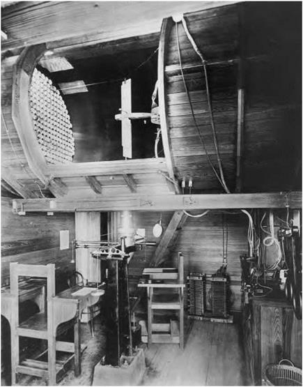
![]() The NACA first began to look at thunderstorms in the 1930s. During that decade, the Agency’s flagship laboratory—the Langley Memorial Aeronautical Laboratory in Hampton, VA—performed a series of tests to determine the nature and magnitude of gust loadings that occur in storm systems. The results of these tests, which engineers performed in Langley’s signature wind tunnels, helped to improve both civilian and military aircraft.[26] But wind tunnels had various limitations, leading to use of specially instrumented research airplanes to effectively use the sky as a laboratory and acquire information unobtainable by traditional tunnel research. This process, most notably associated with the post-World War II X-series of research airplanes, led in time to such future NASA research aircraft as the Boeing 737 "flying laboratory” to study wind shear. Over subsequent decades, the NACAs successor, NASA,
The NACA first began to look at thunderstorms in the 1930s. During that decade, the Agency’s flagship laboratory—the Langley Memorial Aeronautical Laboratory in Hampton, VA—performed a series of tests to determine the nature and magnitude of gust loadings that occur in storm systems. The results of these tests, which engineers performed in Langley’s signature wind tunnels, helped to improve both civilian and military aircraft.[26] But wind tunnels had various limitations, leading to use of specially instrumented research airplanes to effectively use the sky as a laboratory and acquire information unobtainable by traditional tunnel research. This process, most notably associated with the post-World War II X-series of research airplanes, led in time to such future NASA research aircraft as the Boeing 737 "flying laboratory” to study wind shear. Over subsequent decades, the NACAs successor, NASA,
would perform much work to help planes withstand turbulence, wind shear, and gust loadings.
![]() From the 1930s to the 1950s, one of the NACA’s major areas of research was the nature of the boundary layer and the transition from laminar to turbulent flow around an aircraft. But Langley Laboratory also looked at turbulence more broadly, to include gust research and meteorological turbulence influences upon an aircraft in flight. During the previous decade, experimenters had collected measurements of pressure distribution in wind tunnels and flight, but not until the early 1930s did the NACA begin a systematic program to generate data that could be applied by industry to aircraft design, forming a committee to oversee loads research. Eventually, in the late 1930s, Langley created a separate structures research division with a structures research laboratory. By this time, individuals such as Philip Donely, Walter Walker, and Richard V. Rhode had already undertaken wideranging and influential research on flight loads that transformed understanding about the forces acting on aircraft in flight. Rhode, of Langley, won the Wright Brothers Medal in 1935 for his research of gust loads. He pioneered the undertaking of detailed assessments of the maneuvering loads encountered by an airplane in flight. As noted by aerospace historian James Hansen, his concept of the "sharp edge gust” revised previous thinking of gust behavior and the dangers it posed, and it became "the backbone for all gust research.”[27] NACA gust loads research influenced the development of both military and civilian aircraft, as did its research on aerodynamic-induced flight-surface flutter, a problem of particular concern as aircraft design transformed from the era of the biplane to that of the monoplane. The NACA also investigated the loads and stresses experienced by combat aircraft when undertaking abrupt rolling and pullout maneuvers, such as routinely occurred in aerial dogfighting and in dive-bombing.[28] A dive bomber encountered particularly punishing aerodynamic and structural loads as the pilot executed a pullout: abruptly recovering the airplane from a dive and resulting in it
From the 1930s to the 1950s, one of the NACA’s major areas of research was the nature of the boundary layer and the transition from laminar to turbulent flow around an aircraft. But Langley Laboratory also looked at turbulence more broadly, to include gust research and meteorological turbulence influences upon an aircraft in flight. During the previous decade, experimenters had collected measurements of pressure distribution in wind tunnels and flight, but not until the early 1930s did the NACA begin a systematic program to generate data that could be applied by industry to aircraft design, forming a committee to oversee loads research. Eventually, in the late 1930s, Langley created a separate structures research division with a structures research laboratory. By this time, individuals such as Philip Donely, Walter Walker, and Richard V. Rhode had already undertaken wideranging and influential research on flight loads that transformed understanding about the forces acting on aircraft in flight. Rhode, of Langley, won the Wright Brothers Medal in 1935 for his research of gust loads. He pioneered the undertaking of detailed assessments of the maneuvering loads encountered by an airplane in flight. As noted by aerospace historian James Hansen, his concept of the "sharp edge gust” revised previous thinking of gust behavior and the dangers it posed, and it became "the backbone for all gust research.”[27] NACA gust loads research influenced the development of both military and civilian aircraft, as did its research on aerodynamic-induced flight-surface flutter, a problem of particular concern as aircraft design transformed from the era of the biplane to that of the monoplane. The NACA also investigated the loads and stresses experienced by combat aircraft when undertaking abrupt rolling and pullout maneuvers, such as routinely occurred in aerial dogfighting and in dive-bombing.[28] A dive bomber encountered particularly punishing aerodynamic and structural loads as the pilot executed a pullout: abruptly recovering the airplane from a dive and resulting in it
swooping back into the sky. Researchers developed charts showing the relationships between dive angle, speed, and the angle required for recovery. In 1935, the Navy used these charts to establish design requirements for its dive bombers. The loads program gave the American aeronautics community a much better understanding of load distributions between the wing, fuselage, and tail surfaces of aircraft, including high – performance aircraft, and showed how different extreme maneuvers "loaded” these individual surfaces.
![]() In his 1939 Wilbur Wright lecture, George W. Lewis, the NACA’s legendary Director of Aeronautical Research, enumerated three major questions he believed researchers needed to address:
In his 1939 Wilbur Wright lecture, George W. Lewis, the NACA’s legendary Director of Aeronautical Research, enumerated three major questions he believed researchers needed to address:
• What is the nature or structure of atmospheric gusts?
• How do airplanes react to gusts of known structure?
• What is the relation of gusts to weather conditions?[29]
Answering these questions, posed at the close of the biplane era, would consume researchers for much of the next six decades, well into the era of jet airliners and supersonic flight.
The advent of the internally braced monoplane accelerated interest in gust research. The long, increasingly thin, and otherwise unsupported cantilever wing was susceptible to load-induced failure if not well-designed. Thus, the stresses caused by wind gusts became an essential factor in aircraft design, particularly for civilian aircraft. Building on this concern, in 1943, Philip Donely and a group of NACA researchers began design of a gust tunnel at Langley to examine aircraft loads produced by atmospheric turbulence and other unpredictable flow phenomena and to develop devices that would alleviate gusts. The tunnel opened in August 1945. It utilized a jet of air for gust simulation, a catapult for launching scaled models into steady flight, curtains for catching the model after its flight through the gust, and instruments for recording the model’s responses. For several years, the gust tunnel was useful, "often [revealing] values that were not found by the best known methods of calculation. . . in one instance, for example, the gust tunnel tests showed that it would be safe to design the airplane for load increments 17 to 22 percent less than the previously accepted
|
|
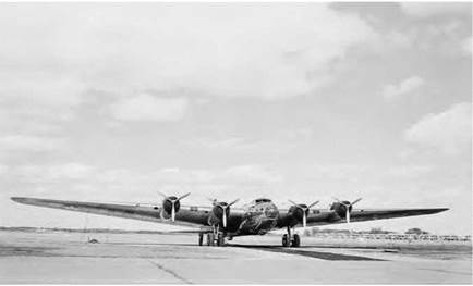
The experimental Boeing XB-1 5 bomber was instrumented by the NACA to acquire gust-induced structural loads data. NASA.
values.”[30] As well, gust researchers took to the air. Civilian aircraft— such as the Aeronca C-2 light, general-aviation airplane, Martin M-130 flying boat, and the Douglas DC-2 airliner—and military aircraft, such as the Boeing XB-15 experimental bomber, were outfitted with special loads recorders (so-called "v-g recorders,” developed by the NACA). Extensive records were made on the weather-induced loads they experienced over various domestic and international air routes.[31]
This work was refined in the postwar era, when new generations of long-range aircraft entered air transport service and were also instrumented to record the loads they experienced during routine airline
operation.[32] Gust load effects likewise constituted a major aspect of early transonic and supersonic aircraft testing, for the high loads involved in transiting from subsonic to supersonic speeds already posed a serious challenge to aircraft designers. Any additional loading, whether from a wind gust or shear, or from the blast of a weapon (such as the overpressure blast wave of an atomic weapon), could easily prove fatal to an already highly loaded aircraft.[33] The advent of the long-range jet bomber and transport—a configuration typically having a long and relatively thin swept wing, and large, thin vertical and horizontal tail surfaces— added further complications to gust research, particularly because the penalty for an abrupt gust loading could be a fatal structural failure. Indeed, on one occasion, while flying through gusty air at low altitude, a Boeing B-52 lost much of its vertical fin, though fortunately, its crew was able to recover and land the large bomber.[34]
![]() The emergence of long-endurance, high-altitude reconnaissance aircraft such as the Lockheed U-2 and Martin RB-57D in the 1950s and the long-range ballistic missile further stimulated research on high – altitude gusts and turbulence. Though seemingly unconnected, both the high-altitude jet airplane and the rocket-boosted ballistic missile required understanding of the nature of upper atmosphere turbulence and gusts. Both transited the upper atmospheric region: the airplane cruising in the high stratosphere for hours, and the ballistic missile
The emergence of long-endurance, high-altitude reconnaissance aircraft such as the Lockheed U-2 and Martin RB-57D in the 1950s and the long-range ballistic missile further stimulated research on high – altitude gusts and turbulence. Though seemingly unconnected, both the high-altitude jet airplane and the rocket-boosted ballistic missile required understanding of the nature of upper atmosphere turbulence and gusts. Both transited the upper atmospheric region: the airplane cruising in the high stratosphere for hours, and the ballistic missile
or space launch vehicle transiting through it within seconds on its way into space. Accordingly, from early 1956 through December 1959, the NACA, in cooperation with the Air Weather Service of the U. S. Air Force, installed gust load recorders on Lockheed U-2 strategic reconnaissance aircraft operating from various domestic and overseas locations, acquiring turbulence data from 20,000 to 75,000 feet over much of the Northern Hemisphere. Researchers concluded that the turbulence problem would not be as severe as previous estimates and high-altitude balloon studies had indicated.[35]
![]() High-altitude loitering aircraft such as the U-2 and RB-57 were followed by high-altitude, high-Mach supersonic cruise aircraft in the early to mid-1960s, typified by Lockheed’s YF-12A Blackbird and North American’s XB-70A Valkyrie, both used by NASA as Mach 3+ Supersonic Transport (SST) surrogates and supersonic cruise research testbeds. Test crews found their encounters with high – altitude gusts at supersonic speeds more objectionable than their exposure to low-altitude gusts at subsonic speeds, even though the given g-loading accelerations caused by gusts were less than those experienced on conventional jet airliners.[36] At the other extreme of aircraft performance, in 1961, the Federal Aviation Agency (FAA) requested NASA assistance to document the gust and maneuver loads and performance of general-aviation aircraft. Until the program was terminated in 1982, over 35,000 flight-hours of data were assembled from 95 airplanes, representing every category of general-aviation airplane, from single-engine personal craft to twin-engine business airplanes and including such specialized types as crop-dusters and aerobatic aircraft.[37]
High-altitude loitering aircraft such as the U-2 and RB-57 were followed by high-altitude, high-Mach supersonic cruise aircraft in the early to mid-1960s, typified by Lockheed’s YF-12A Blackbird and North American’s XB-70A Valkyrie, both used by NASA as Mach 3+ Supersonic Transport (SST) surrogates and supersonic cruise research testbeds. Test crews found their encounters with high – altitude gusts at supersonic speeds more objectionable than their exposure to low-altitude gusts at subsonic speeds, even though the given g-loading accelerations caused by gusts were less than those experienced on conventional jet airliners.[36] At the other extreme of aircraft performance, in 1961, the Federal Aviation Agency (FAA) requested NASA assistance to document the gust and maneuver loads and performance of general-aviation aircraft. Until the program was terminated in 1982, over 35,000 flight-hours of data were assembled from 95 airplanes, representing every category of general-aviation airplane, from single-engine personal craft to twin-engine business airplanes and including such specialized types as crop-dusters and aerobatic aircraft.[37]
Along with studies of the upper atmosphere by direct measurement came studies on how to improve turbulence detection and avoidance, and how to measure and simulate the fury of turbulent storms. In 19461947, the U. S. Weather Bureau sponsored a study of turbulence as part of a thunderstorm study project. Out of this effort, in 1948, researchers from the NACA and elsewhere concluded that ground radar, if properly used, could detect storms, enabling aircraft to avoid them. Weather radar became a common feature of airliners, their once-metal nose caps replaced by distinctive black radomes.[38] By the late 1970s, most wind shear research was being done by specialists in atmospheric science, geophysical scientists, and those in the emerging field of mesometeorology— the study of small atmospheric phenomena, such as thunderstorms and tornadoes, and the detailed structure of larger weather events.[39] Although turbulent flow in the boundary layer is important to study in the laboratory, the violent phenomenon of microburst wind shear cannot be sufficiently understood without direct contact, investigation, and experimentation.[40]
![]() Microburst loadings constitute a threat to aircraft, particularly during approach and landing. No one knows how many aircraft accidents have been caused by wind shear, though the number is certainly considerable. The NACA had done thunderstorm research during World War II, but its instrumentation was not nearly sophisticated enough to detect microburst (or thunderstorm downdraft) wind shear. NASA would join with the FAA in 1986 to systematically fight wind shear and would only have a small pool of existing wind shear research data from which to draw.[41]
Microburst loadings constitute a threat to aircraft, particularly during approach and landing. No one knows how many aircraft accidents have been caused by wind shear, though the number is certainly considerable. The NACA had done thunderstorm research during World War II, but its instrumentation was not nearly sophisticated enough to detect microburst (or thunderstorm downdraft) wind shear. NASA would join with the FAA in 1986 to systematically fight wind shear and would only have a small pool of existing wind shear research data from which to draw.[41]
![]()
|
 |
Wind Shear Emerges as an Urgent Aviation Safety Issue
In 1972, the FAA had instituted a small wind shear research program, with emphasis upon developing sensors that could plot wind speed and direction from ground level up to 2,000 feet above ground level (AGL). Even so, the agency’s major focus was on wake vortex impingement. The powerful vortexes streaming behind newer-generation wide-body aircraft could—and sometimes did—flip smaller, lighter aircraft out of control. Serious enough at high altitude, these inadvertent excursions could be disastrous if low over the ground, such as during landing and takeoff, where a pilot had little room to recover. By 1975, the FAA had developed an experimental Wake Vortex Advisory System, which it installed later that year at Chicago’s busy O’Hare International Airport. NASA undertook a detailed examination of wake vortex studies, both in tunnel tests and with a variety of aircraft, including the Boeing 727 and 747, Lockheed L-1011, and smaller aircraft, such as the Gates Learjet, helicopters, and general-aviation aircraft.
But it was wind shear, not wake vortex impingement, which grew into a major civil aviation concern, and the onset came with stunning and deadly swiftness.[42] Three accidents from 1973 to 1975 highlighted the extreme danger it posed. On the afternoon of December 17, 1973, while making a landing approach in rain and fog, an Iberia Airlines McDonnell-Douglas DC-10 wide-body abruptly sank below the glide – slope just seconds before touchdown, impacting amid the approach lights of Runway 33L at Boston’s Logan Airport. No one died, but the crash seriously injured 16 of the 151 passengers and crew. The subsequent National Transportation Safety Board (NTSB) report determined "that the captain did not recognize, and may have been unable to recognize an increased rate of descent” triggered "by an encounter with a low – altitude wind shear at a critical point in the landing approach.”[43] Then, on June 24, 1975, Eastern Air Lines’ Flight 66, a Boeing 727, crashed on approach to John F. Kennedy International Airport’s Runway 22L. This time, 113 of the 124 passengers and crew perished. All afternoon, flights had encountered and reported wind shear conditions, and at least one pilot had recommended closing the runway. Another Eastern captain, flying a Lockheed L-1011 TriStar, prudently abandoned his approach and landed instead at Newark. Shortly after the L-1011 diverted, the EAL Boeing 727 impacted almost a half mile short of the runway threshold, again amid the approach lights, breaking apart and bursting into flames. Again, wind shear was to blame, but the NTSB also faulted Kennedy’s air traffic controllers for not diverting the 727 to another runway, after the EAL TriStar’s earlier aborted approach.[44]
![]() Just weeks later, on August 7, Continental Flight 426, another Boeing 727, crashed during a stormy takeoff from Denver’s Stapleton
Just weeks later, on August 7, Continental Flight 426, another Boeing 727, crashed during a stormy takeoff from Denver’s Stapleton
International Airport. Just as the airliner began its climb after lifting off the runway, the crewmembers encountered a wind shear so severe that they could not maintain level flight despite application of full power and maintenance of a flight attitude that ensured the wings were producing maximum lift.[45] The plane pancaked in level attitude on flat, open ground, sustaining serious damage. No lives were lost, though 15 of the 134 passengers and crew were injured.
![]() Less than a year later, on June 23, 1976, Allegheny Airlines Flight 121, a Douglas DC-9 twin-engine medium-range jetliner, crashed during an attempted go-around at Philadelphia International Airport. The pilot, confronting "severe horizontal and vertical wind shears near the ground,” abandoned his landing approach to Runway 27R. As controllers in the airport tower watched, the straining DC-9 descended in a nose – high attitude, pancaking onto a taxiway and sliding to a stop. The fact that it hit nose-high, wings level, and on flat terrain undoubtedly saved lives. Even so, 86 of the plane’s 106 passengers and crew were seriously injured, including the entire crew.[46]
Less than a year later, on June 23, 1976, Allegheny Airlines Flight 121, a Douglas DC-9 twin-engine medium-range jetliner, crashed during an attempted go-around at Philadelphia International Airport. The pilot, confronting "severe horizontal and vertical wind shears near the ground,” abandoned his landing approach to Runway 27R. As controllers in the airport tower watched, the straining DC-9 descended in a nose – high attitude, pancaking onto a taxiway and sliding to a stop. The fact that it hit nose-high, wings level, and on flat terrain undoubtedly saved lives. Even so, 86 of the plane’s 106 passengers and crew were seriously injured, including the entire crew.[46]
In these cases, wind shear brought about by thunderstorm downdrafts (microbursts), rather than the milder wind shear produced by gust fronts, caused these accidents. This led to a major reinterpretation of the wind shear-causing phenomena that most endangered low-flying planes. Before these accidents, meteorologists believed that gust fronts, or the leading edge of a large dome of rain-cooled air, provided the most dangerous sources of wind shear. Now, using data gathered from the planes that had crashed and from weather radar, scientists, engineers, and designers came to realize that the small, focused, jet-like downdraft columns characteristic of microbursts produced the most threatening kind of wind shear.[47]
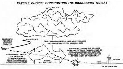
Microburst wind shear poses an insidious danger for an aircraft. An aircraft landing will typically encounter the horizontal outflow of a microburst as a headwind, which increases its lift and airspeed, tempting
|
Fateful choice: confronting the microburst threat. Richard P. Hallion. |
the pilot to reduce power. But then the airplane encounters the descending vertical column as an abrupt downdraft, and its speed and altitude both fall. As it continues onward, it will exit the central downflow and experience the horizontal outflow, now as a tailwind. At this point, the airplane is already descending at low speed. The tailwind seals its fate, robbing it of even more airspeed and, hence, lift. It then stalls (that is, loses all lift) and plunges to Earth. As NASA testing would reveal, professional pilots generally need between 10 to 40 seconds of warning to avoid the problems of wind shear.[48]
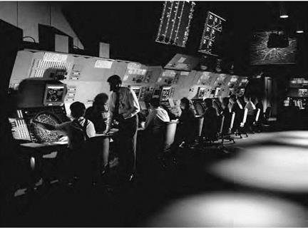
Goaded by these accidents and NTSB recommendations that the FAA improve its weather advisory and runway selection procedures, "step up research on methods of detecting the [wind shear] phenomenon,” and develop aircrew wind shear training process, the FAA mandated installation at U. S. airports of a new Low-Level Windshear Alert System (LLWAS), which employed acoustic Doppler radar, technically similar to the FAA’s Wake Vortex Advisory System installed at O’Hare.[49] The LLWAS incorporated a variety of equipment that measured wind velocity (wind speed and direction). This equipment included a master station, which had a main computer and system console to monitor LLWAS performance, and a transceiver, which transmitted signals
to the system’s remote stations. The master station had several visual computer displays and auditory alarms for aircraft controllers. The remote stations had wind sensors made of sonic anemometers mounted on metal pipes. Each remote station was enclosed in a steel box with a radio transceiver, power supplies, and battery backup. Every airport outfitted with this system used multiple anemometer stations to effectively map the nature of wind events in and around the airport’s runways.[50]
![]() At the end of March 1981, over 70 representatives from NASA, the FAA, the military, the airline community, the aerospace industry, and academia met at the University of Tennessee Space Institute in Tullahoma to explore weather-related aviation issues. Out of that came a list of recommendations for further joint research, many of which directly addressed the wind shear issue and the need for better detection and warning systems. As the report summarized:
At the end of March 1981, over 70 representatives from NASA, the FAA, the military, the airline community, the aerospace industry, and academia met at the University of Tennessee Space Institute in Tullahoma to explore weather-related aviation issues. Out of that came a list of recommendations for further joint research, many of which directly addressed the wind shear issue and the need for better detection and warning systems. As the report summarized:
1. There is a critical need to increase the data base for wind and temperature aloft forecasts both from a more frequent updating of the data as well as improved accuracy in the data, and thus, also in the forecasts which are used in flight planning. This will entail the development of rational definitions of short term variations in intensity and scale length (of turbulence) which will result in more accurate forecasts which should also meet the need to improve numerical forecast modeling requirements relative to winds and temperatures aloft.
2. The development of an on-board system to detect wind induced turbulence should be beneficial to meeting the requirement for an investigation of the subjective evaluation of turbulence "feel” as a function of motion drive algorithms.
3. More frequency reporting of wind shift in the terminal area is needed along with greater accuracy in forecasting.
4. T here is a need to investigate the effects of unequal wind components acting across the span of an airfoil.
5. The FAA Simulator Certification Division should monitor the work to be done in conjunction with the JAWS project relative to the effects of wind shear on aircraft performance.
6. ![]() Robert Steinberg’s ASDAR effort should be utilized as soon as possible, in fact it should be encouraged or demanded as an operational system beneficial for flight planning, specifically where winds are involved.
Robert Steinberg’s ASDAR effort should be utilized as soon as possible, in fact it should be encouraged or demanded as an operational system beneficial for flight planning, specifically where winds are involved.
7. There is an urgent need to review the way pilots are trained to handle wind shear. The present method, as indicated in the current advisory circular, of immediately pulling to stick shaker on encountering wind shear could be a dangerous procedure. It is suggested the circular be changed to recommend the procedure to hold at whatever airspeed the aircraft is at when the pilot realizes he is encountering a wind shear and apply maximum power, and that he not pull to stick shaker except to flare when encountering ground effect to minimize impact or to land successfully or to effect a go-around.
8. Need to develop a clear non-technical presentation of wind shear which will help to provide improved training for pilots relative to wind shear phenomena. Such training is of particular importance to pilots of high performance, corporate, and commercially used aircraft.
9. Need to develop an ICAO type standard terminology for describing the effects of windshear on flight performance.
10. The ATC system should be enhanced to provide operational assistance to pilots regarding hazardous weather areas and in view of the envisioned controller workloads generated, perfecting automated transmissions containing this type of information to the cockpit as rapidly and as economically as practicab1e.
11. In order to improve the detection in real time of hazardous weather, it is recommended that FAA, NOAA, NWS, and DOD jointly address the problem of fragmental meteorological collection, processing, and dissemination pursuant to developing a system dedicated to making effective use of perishable weather information. Coupled with this would be the need to conduct a cost
benefit study relative to the benefits that could be realized through the use of such items as a common winds and temperature aloft reporting by use of automated sensors on aircraft.
12. ![]() Develop a capabi1ity for very accurate four to six minute forecasts of wind changes which would require terminal reconfigurations or changing runways.
Develop a capabi1ity for very accurate four to six minute forecasts of wind changes which would require terminal reconfigurations or changing runways.
13. Due to the inadequate detection of clear air turbulence an investigation is needed to determine what has happened to the promising detection systems that have been reported and recommended in previous workshops.
14. Improve the detection and warning of windshear by developing on-board sensors as well as continuing the development of emerging technology for ground – based sensors.
15. Need to collect true three and four dimensional wind shear data for use in flight simulation programs.
16. Recommend that any systems whether airborne or ground based that can provide advance or immediate alert to pilots and controllers should be pursued.
17. Need to continue the development of Doppler radar technology to detect the wind shear hazard, and that this be continued at an accelerated pace.
18. Need for airplane manufacturers to take into consideration the effect of phenomena such as microbursts which produce strong periodic longitudinal wind perturbations at the aircraft phugoid frequency.
19. Consideration should be given, by manufacturers, to consider gust alleviation devices on new aircraft to provide a softer ride through turbulence.
20. Need to develop systems to automatically detect hazardous weather phenomena through signature recognition algorithms and automatically data linking alert messages to pilots and air traffic controllers.[51]
Given the subsequent history of NASA’s research on the wind shear problem (and others), many of these recommendations presciently forecast the direction of Agency and industry research and development efforts.
![]() Unfortunately, that did not come in time to prevent yet another series of microburst-related accidents. That series of catastrophes effectively elevated microburst wind shear research to the status of a national air safety emergency. By the early 1980s, 58 U. S. airports had installed LLWAS. Although LLWAS constituted a great improvement over verbal observations and warnings by pilots communicated to air traffic controllers, LLWAS sensing technology was not mature or sophisticated enough to remedy the wind shear threat. Early LLWAS sensors were installed without fullest knowledge of microburst characteristics. They were usually installed in too-few numbers, placed too close to the airport (instead of farther out on the approach and departure paths of the runways), and, worst, were optimized to detect gust fronts (the traditional pre – Fujita way of regarding wind shear)—not the columnar downdrafts and horizontal outflows characteristic of the most dangerous shear flows. Thus, wind shear could still strike, and viciously so.
Unfortunately, that did not come in time to prevent yet another series of microburst-related accidents. That series of catastrophes effectively elevated microburst wind shear research to the status of a national air safety emergency. By the early 1980s, 58 U. S. airports had installed LLWAS. Although LLWAS constituted a great improvement over verbal observations and warnings by pilots communicated to air traffic controllers, LLWAS sensing technology was not mature or sophisticated enough to remedy the wind shear threat. Early LLWAS sensors were installed without fullest knowledge of microburst characteristics. They were usually installed in too-few numbers, placed too close to the airport (instead of farther out on the approach and departure paths of the runways), and, worst, were optimized to detect gust fronts (the traditional pre – Fujita way of regarding wind shear)—not the columnar downdrafts and horizontal outflows characteristic of the most dangerous shear flows. Thus, wind shear could still strike, and viciously so.
On July 9, 1982, Clipper 759, a Pan American World Airways Boeing 727, took off from the New Orleans airport amid showers and "gusty, variable, and swirling” winds.[52] Almost immediately, it began to descend, having attained an altitude of no more than 150 feet. It hit trees, continued onward for almost another half mile, and then crashed into residential housing, exploding in flames. All 146 passengers and crew died, as did 8 people on the ground; 11 houses were destroyed or "substantially” damaged, and another 16 people on the ground were injured. The NTSB concluded that the probable cause of the accident was "the airplane’s encounter during the liftoff and initial climb phase of flight with a microburst-induced wind shear which imposed a downdraft and a decreasing headwind, the effects of which the pilot would have had difficulty recognizing and reacting to in time for the airplane’s descent to be arrested before its impact with trees.” Significantly, it also noted, "Contributing to the accident was the limited capability of current ground based low level wind shear detection technology [the LLWAS] to provide
definitive guidance for controllers and pilots for use in avoiding low level wind shear encounters.”[53] This tragic accident impelled Congress to direct the FAA to join with the National Academy of Sciences (NAS) to "study the state of knowledge, alternative approaches and the consequences of wind shear alert and severe weather condition standards relating to take off and landing clearances for commercial and general aviation aircraft.”[54] As the FAA responded to these misfortunes and accelerated its research on wind shear, NASA researchers accelerated their own wind shear research. In the late 1970s, NASA Ames Research Center contracted with Bolt, Baranek, and Newman, Inc., of Cambridge, MA, to perform studies of "the effects of wind-shears on the approach performance of a STOL aircraft. . . using the optimal-control model of the human operator.” In laymen’s terms, this meant that the company used existing data to mathematically simulate the combined pilot/aircraft reaction to various wind shear situations and to deduce and explain how the pilot should manipulate the aircraft for maximum safety in such situations. Although useful, these studies did not eliminate the wind shear problem.[55] Throughout the 1980s, NASA research into thunderstorm phenomena involving wind shear continued. Double-vortex thunderstorms and their potential effects on aviation were of particular interest. Double-vortex storms involve a pair of vortexes present in the storm’s dynamic updraft that rotate in opposite directions. This pair forms when the cylindrical thermal updraft of a thunderstorm penetrates the upper-level air and there is a large amount of vertical wind shear between the lower – and upper-level air layers. Researchers produced a numerical tornado prediction scheme based on the movement of the double-vortex thunderstorm. A component of this scheme was the Energy-Shear Index (ESI), which researchers calculated from radiosonde measurements. The index integrated parameters that were representative of thermal instability and the blocking effect. It indicated
![]()
|
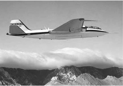
NASA 809, a Martin B-57B flown by Dryden research crews in 1982 for gust and microburst research. NASA. |
environments appropriate for the development of double-vortex thunderstorms and tornadoes, which would help pilots and flight controllers determine safe flying conditions.[56]
In 1982, in partnership with the National Center for Atmospheric Research (NCAR), the University of Chicago, the National Oceanic Atmospheric Administration (NOAA), the National Science Foundation (NSF), and the FAA, NASA vigorously supported the Joint Airport Weather Studies (JAWS) effort. NASA research pilots and flight research engineers from the Ames-Dryden Flight Research Facility (now the NASA Dryden Flight Research Center) participated in the JAWS program from mid-May through mid-August 1982, using a specially instrumented Martin B-57B jet bomber. NASA researchers selected the B-57B for its strength, flying it on low-level wind shear research flights around the Sierra Mountains near Edwards Air Force Base (AFB), CA, about the Rockies near Denver, CO, around Marshall Space Flight Center, AL, and near Oklahoma City, OK. Raw data were digitally collected on microbursts, gust fronts, mesocyclones, torna
does, funnel clouds, and hail storms; converted into engineering format at the Langley Research Center; and then analyzed at Marshall Space Flight Center and the University of Tennessee Space Institute at Tullahoma. Researchers found that some microbursts recorded during the JAWS program created wind shear too extreme for landing or departing airliners to survive if they encountered it at an altitude less than 500 feet.[57] In the most severe case recorded, the B-57B experienced an abrupt 30-knot speed increase within less than 500 feet of distance traveled and then a gradual decrease of 50 knots over 3.2 miles, clear evidence of encountering the headwind outflow of a microburst and then the tailwind outflow as the plane transited through the microburst.[58]
![]() At the same time, the Center for Turbulence Research (CTR), run jointly by NASA and Stanford University, pioneered using an early parallel computer, the Illiac IV, to perform large turbulence simulations, something previously unachievable. CTR performed the first of these simulations and made the data available to researchers around the globe. Scientists and engineers tested theories, evaluated modeling ideas, and, in some cases, calibrated measuring instruments on the basis of these data. A 5-minute motion picture of simulated turbulent flow provided an attention-catching visual for the scientific community.[59]
At the same time, the Center for Turbulence Research (CTR), run jointly by NASA and Stanford University, pioneered using an early parallel computer, the Illiac IV, to perform large turbulence simulations, something previously unachievable. CTR performed the first of these simulations and made the data available to researchers around the globe. Scientists and engineers tested theories, evaluated modeling ideas, and, in some cases, calibrated measuring instruments on the basis of these data. A 5-minute motion picture of simulated turbulent flow provided an attention-catching visual for the scientific community.[59]
In 1984, NASA and FAA representatives met at Langley Research Center to review the status of wind shear research and progress toward developing sensor systems and preventing disastrous accidents. Out of this, researcher Roland L. Bowles conceptualized a joint NASA-FAA
program to develop an airborne detector system, perhaps one that would be forward-looking and thus able to furnish real-time warning to an airline crew of wind shear hazards in its path. Unfortunately, before this program could yield beneficial results, yet another wind shear accident followed the dismal succession of its predecessors: the crash of Delta Flight 191 at Dallas-Fort Worth International Airport (DFW) on August 2, 1985.[60]
![]() Delta Flight 191 was a Lockheed L-1011 TriStar wide-body jumbo jet. As it descended toward Runway 17L amid a violent turbulence – producing thunderstorm, a storm cell produced a microburst directly in the airliner’s path. The L-1011 entered the fury of the outflow when only 800 feet above ground and at a low speed and energy state. As the L-1011 transitioned through the microburst, a lift-enhancing headwind of 26 knots abruptly dropped to zero and, as the plane sank in the downdraft column, then became a 46-knot tailwind, robbing it of lift. At low altitude, the pilots had insufficient room for recovery, and so, just 38 seconds after beginning its approach, Delta Flight 191 plunged to Earth, a mile short of the runway threshold. It broke up in a fiery heap of wreckage, slewing across a highway and crashing into some water tanks before coming to a rest, burning furiously. The accident claimed the lives of 136 passengers and crewmembers and the driver of a passing automobile. Just 24 passengers and 3 of its crew survived: only 2 were without injury. [61] Among the victims were several senior staff members from IBM, including computer pioneer Don Estridge, father of the IBM PC. Once again, the NTSB blamed an "encounter at low altitude with a microburst-induced, severe wind shear” from a rapidly developing thunderstorm on the final approach course. But the accident illustrated as well the immature capabilities of the LLWAS at that time; only after Flight 191 had crashed did the DFW LLWAS detect the fatal microburst.[62]
Delta Flight 191 was a Lockheed L-1011 TriStar wide-body jumbo jet. As it descended toward Runway 17L amid a violent turbulence – producing thunderstorm, a storm cell produced a microburst directly in the airliner’s path. The L-1011 entered the fury of the outflow when only 800 feet above ground and at a low speed and energy state. As the L-1011 transitioned through the microburst, a lift-enhancing headwind of 26 knots abruptly dropped to zero and, as the plane sank in the downdraft column, then became a 46-knot tailwind, robbing it of lift. At low altitude, the pilots had insufficient room for recovery, and so, just 38 seconds after beginning its approach, Delta Flight 191 plunged to Earth, a mile short of the runway threshold. It broke up in a fiery heap of wreckage, slewing across a highway and crashing into some water tanks before coming to a rest, burning furiously. The accident claimed the lives of 136 passengers and crewmembers and the driver of a passing automobile. Just 24 passengers and 3 of its crew survived: only 2 were without injury. [61] Among the victims were several senior staff members from IBM, including computer pioneer Don Estridge, father of the IBM PC. Once again, the NTSB blamed an "encounter at low altitude with a microburst-induced, severe wind shear” from a rapidly developing thunderstorm on the final approach course. But the accident illustrated as well the immature capabilities of the LLWAS at that time; only after Flight 191 had crashed did the DFW LLWAS detect the fatal microburst.[62]
The Dallas accident resulted in widespread shock because of its large number of fatalities. It particularly affected airline crews, as American Airlines Capt. Wallace M. Gillman recalled vividly at a NASA-sponsored 1990 meeting of international experts in wind shear:
![]() About one week after Delta 191’s accident in Dallas, I was taxiing out to take off on Runway 17R at DFW Airport. Everybody was very conscience of wind shear after that accident. I remember there were some storms coming in from the northwest and we were watching it as we were in a line of airplanes waiting to take off. We looked at the wind socks. We were listening to the tower reports from the LLWAS system, the winds at various portions around the airport. I was number 2 for takeoff and I said to my co-pilot, "I’m not going to go on this runway.”
About one week after Delta 191’s accident in Dallas, I was taxiing out to take off on Runway 17R at DFW Airport. Everybody was very conscience of wind shear after that accident. I remember there were some storms coming in from the northwest and we were watching it as we were in a line of airplanes waiting to take off. We looked at the wind socks. We were listening to the tower reports from the LLWAS system, the winds at various portions around the airport. I was number 2 for takeoff and I said to my co-pilot, "I’m not going to go on this runway.”
But just at that time, the number 1 crew in line, Pan Am, said,
"I’m not going to go.” Then the whole line said, "We’re not going to go” then the tower taxies us all down the runway, took us about 15 minutes, down to the other end. By that time the storm had kind of passed by and we all launched to the north.[63]


