Wind Tunnel Free-Flight Techniques
Charles Zimmerman energetically continued his interest in free-flight models after the successful introduction of his 15-foot free-spinning tunnel. His next ambition was to provide a capability of investigating the dynamic stability and control of aircraft in conventional flight. His approach to this goal was to simulate the unpowered gliding flight of a model airplane in still air but to accomplish this goal in a wind tunnel with the model within view of the tunnel operators. Without power, the model would be in equilibrium in descending flight, so the tunnel airstream had to be at an inclined angle relative to the horizon. Zimmerman designed a 5-foot-diameter wind tunnel that was mounted in a yoke-like support structure such that the tunnel could be pivoted and its airstream could
|
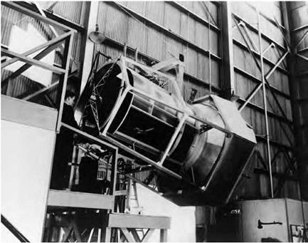
The Langley 5-Foot Free-Flight Tunnel was mounted in a yoke assembly that permitted the test section to be tilted down for simulation of gliding flight. Its inventor, Charles Zimmerman, is on the left controlling the model, while the tunnel operator is behind the test section. NASA. |
simulate various descent angles. Known as the Langley 5-Foot Free-Flight Tunnel, this exploratory apparatus was operated by two researchers—a tunnel operator, who controlled the airspeed and tilt angle of the tunnel, and a pilot, who controlled the model and assessed its behavior via a control box with a fine wire connection to the model’s control actuators.[449]
Very positive results obtained in this proof-of-concept apparatus led to the design and construction of a larger 12-Foot Free-Flight Tunnel in 1939. Housed in a 60-foot-diameter sphere that permitted the tunnel to tilt upward and downward, the Langley 12-Foot Free-Flight Tunnel was designed for free-flight testing of powered as well as unpowered models. A three-person crew was used in the testing, including a tunnel airspeed controller, a tunnel tilt-angle operator, and an evaluation pilot.
The tunnel operated as the premier NACA low-speed free-flight facility for over 20 years, supporting advances in fundamental dynamic
|
|

![]()
Safety Cable
Operator
» Pitch I Pilot ^ Test Conductor
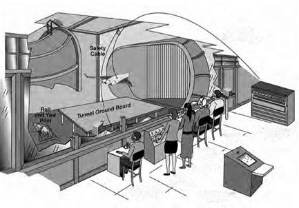
Test setup for free-flight studies at Langley. The pitch pilot is in a balcony at the side of the test section. The pilot who controls the rolling and yawing motions is at the rear of the tunnel. NASA.
stability and control theory as well as specific airplane development programs. After the 1959 decision to transfer the free-flight activities to the Full-Scale Tunnel, the tunnel pivot was fixed in a horizontal position, and the facility has continued to operate as a NASA low-cost laboratory-type tunnel for exploratory testing of advanced concepts.
Relocation of the free-flight testing to the Full-Scale Tunnel made that tunnel the focal point of free-flight applications at Langley for the next 50 years.[450] The move required updates to the test technique and the free-flight models. The test crew increased to four or more individuals responsible for piloting duties, thrust control, tunnel operations, and model retrieval and was located at two sites within the wind tunnel building. One group of researchers was in a balcony at one side of the open-throat test section, while a pilot who controlled the rolling and yawing motions of the model was in an enclosure at the rear of the test section within the structure of the tunnel exit-flow collector. Models of jet aircraft were typically powered by compressed air, and the level of
thrust was controlled by a thrust pilot in the balcony. Next to the thrust pilot was a pitch pilot who controlled the longitudinal motions of the model and conducted assessments of dynamic longitudinal stability and control during flight tests. Other key members of the test crew in the balcony included the test conductor and the tunnel airspeed operator.
A light, flexible cable attached to the model supplied the model with the compressed air, electric power for control actuators, and transmission of signals for the controls and sensors carried within the model. A portion of the cable was made up of steel cable that passed through a pulley above the test section and was used to retrieve the model when the test was terminated or when an uncontrollable motion occurred. The flight cable was kept slack during the flight tests by a safety-cable operator in the balcony who accomplished the job with a high-speed winch.[451]
Free-flight models in the Full-Scale Tunnel typically had model wingspans of about 6 feet and weighed about 100 pounds. Propulsion was provided by compressed air ejectors, miniature turbofans, and high thrust/ weight propeller motors. The materials used to fabricate models changed from the simple balsa free-flight construction used in the 12-Foot Free – Flight Tunnel to high-strength, lightweight composite materials. The control systems used by the free-flight models simulated the complex feedback and stabilization logic used in flight control systems for contemporary aircraft. The control signals from the pilot stations were transmitted to a digital computer in the balcony, and a special software program computed the control surface deflections required in response to pilot inputs, sensor feedbacks, and other control system inputs. Typical sensor packages included control-position indicators, linear accelerometers, and angular-rate gyros. Many models used nose-boom-mounted vanes for feedback of angle of attack and angle of sideslip, similar to systems used on full-scale aircraft. Data obtained from the flights included optical and digital recordings of model motions and pilot comments as well as analysis of the model’s response characteristics.
The NACA and NASA also developed wind tunnel free-flight testing techniques to determine high-speed aerodynamic characteristics, dynamic stability of aircraft, Earth atmosphere entry configurations, planetary probes, and aerobraking concepts. The NASA Ames Research Center led the development of such facilities starting in the 1940s with the Ames
Supersonic Free-Flight Tunnel (SFFT).[452] The SFFT, which was similar in many respects to ballistic range facilities used for testing munitions, was designed for aerodynamic and dynamic stability research at high supersonic Mach numbers (Mach numbers in excess of 10). In the SFFT, the model was fired at high speeds upstream into a supersonic airstream (typically Mach 2.0). Windows for shadowgraph photography were along the top and sides of the test section.
Data obtained from motion time histories and measurements of the model’s attitudes during the brief flights were used to obtain aerodynamic and dynamic stability characteristics. The small research models had to be extremely strong to withstand high accelerations during the launch (up to 100,000 g’s), yet light enough to meet requirements for dynamic mass scaling (moments of inertia). Launching the models without angular disturbances or damage was challenging and required extensive development and experience. The SFFT was completed in late 1949 and became operational in the early 1950s.
Ames later brought online its most advanced aeroballistic testing capability, the Ames Hypervelocity Free-Flight Aerodynamic Facility (HFFAF), in 1964. This facility was initially developed in support of the Apollo program and utilized both light-gas gun and shock tube technology to produce lunar return and atmospheric entry. At one end of the test section, a family of light-gas gun was used to launch specimens into the test section, while at the opposite end, a large shock tube could be simultaneously used to produce a counterflowing airstream (the result being Mach numbers of about 30). This counterflow mode of operation proved to be very challenging and was used for only a brief time from 1968 to 1971. Throughout much of the 1970s and 1980s, this versatile facility was operated as a traditional aeroballistic range, using the guns to launch models into quiescent air (or some other test gas), or as a hypervelocity impact test facility. From 1989 through 1995, the facility was operated as a shock tube-driven wind tunnel for scramjet propulsion testing. In 1997, the HFFAF underwent a major refurbishment and was returned to an aeroballistic mode of operation. It continues to operate in this mode and is NASA’s only remaining aeroballistic test facility.[453]


