Category NASA’S CONTRIBUTIONS TO AERONAUTICS

Skewed Logic: The RPRV Explores Jones’s Oblique Wing

In the early 1970s—a time when fuel prices were soaring—scientists at NASA Ames Research Center and NASA Dryden began investigat­ing an aircraft concept featuring a wing that could be rotated about a

central pivot. For low-speed flight, the planform would present a con­ventional straight wing, perpendicular to the fuselage. At higher speeds, the wing would be skewed to an oblique angle, with one side swept for­ward and the other aft to enhance transonic cruise efficiency by reduc­ing drag. Dr. Robert T. Jones, a senior scientist at Ames (and, early in his career, the American father of the swept wing), proposed the single­pivot oblique wing concept for a future supersonic transport. Studies indicated that such a plane flying at 1,000 mph would achieve twice the fuel economy of supersonic transports then operational, including the Concorde and Tu-144.

Jones built a 5.5-foot wingspan, radio-controlled model to test the configuration’s basic handling qualities. The wing, mounted atop the fuselage, pivoted so that the left side moved forward and the right side moved aft to take advantage of propeller torque to cancel rolling moment. Burnett L. Gadberg controlled the model during flight tests at wing angles up to 45 degrees and speeds between 50 and 100 mph. He found that the model remained stable at high sweep angles and could be con­trolled with decoupled aerodynamic control surfaces.40 In order to fur­ther investigate the aerodynamic characteristics of an oblique wing and develop control laws necessary to achieve acceptable handling quali­ties, a $200,000 contract was awarded for design and development of a subsonic, remotely piloted Oblique Wing Research Aircraft (OWRA). Rod Bailey at Ames led the design effort, originally conceiving an all­wing vehicle. Because of stability and control issues, however, a tail assembly was eventually added.

Built by Developmental Sciences, Inc., of City of Industry, CA, the OWRA had a narrow cylindrical fuselage tipped with a glass dome—like a cyclopean eye—containing a television camera. Power was provided by a McCullough 90-horsepower, 4-cylinder, air-cooled, reciprocating engine mounted in the center of a 22-foot-span, oval planform wing. The engine drove a pusher propeller, shrouded in a 50-inch-diameter duct to reduce risk of crash damage. To further ensure survivability and ease of repair, key structural components were constructed of fiberglass epoxy composites. A two-axis, gyro-controlled autopilot provided sta­bilization for pitch, roll, and altitude hold, but the vacuum-tube-based sensors resulted in a significant weight penalty.[919] By December 1975, following 3 years of development with minimal resources, construction of the OWRA was essentially complete. Engineers evaluated the vehicle in two rounds of wind tunnel testing to collect preliminary data. Tests in a 7- by 10-foot tunnel helped designers refine the basic layout of the aircraft and confirmed trends noted with the original subscale model.

Milton O. Thompson, chief engineer at Dryden, recommended flying the vehicle from a remote site such as Bicycle Lake, at nearby U. S. Army Fort Irwin, or Mud Lake, NV, in order to minimize any adverse pub­licity should an incident occur. Based on his recommendation, Bicycle Lake was selected for taxi testing.[920] During these preliminary trials, engineers discovered that the OWRA—designed to have a top speed of 146 knots—was considerably underpowered. Additionally, the air­craft was damaged when it flipped over on the lakebed following loss of signal from the control transmitter. After being rebuilt, the OWRA was tested in a 40- by 80-foot Ames wind tunnel in order to evaluate three different tail configurations and determine static aerodynamic characteristics at varying wing-sweep angles. The results of these tests provided data required for ground simulation and training for pilot Jim Martin.[921] In April 1976, the OWRA was delivered to Dryden for test­ing. Technicians spent the next several months installing avionics and instrumentation, conducting systems checkouts, and developing a flight plan through detailed simulations. Taxi testing took place August 3, and the first flight was accomplished 3 days later at Rogers Dry Lake.

The results of the 24-minute flight indicated insufficient lon­gitudinal stability because of a center of gravity located too far aft. Subsequently, the aircraft was modified with a 33-percent-larger vertical stabilizer, which was also moved back 3 feet, and a rede­signed flight control system, which alleviated trim and stability prob­lems. During a second flight, on September 16, stability and control data were collected to wing skew angles up to 30 degrees. Although severe radio-control system problems were encountered throughout the flight, all mission objectives were accomplished. A third and final flight was made October 20. Despite some control difficulties, researchers were able to obtain data at wing-skew angles up to 45 degrees, boost­ing confidence in plans for development of piloted oblique wing aircraft designs such as the Ames-Dryden AD-1 research airplane that was successfully flown in the early 1980s.[922]

Gathering the Data for Supersonic Airplane Design

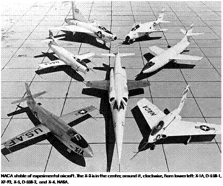
Подпись: 10NACA supersonic research after 1947 concentrated on the practical problems of designing supersonic airplanes. Basic transonic and low supersonic test data were collected in a series of experimental aircraft that did not suffer from the necessary compromises of operational mil­itary aircraft. The test programs were generally joint efforts with the Air Force and/or Navy, which needed the data in order to make reasonable decisions for future aircraft. The X-1 (USAF) and D-558-1 and D-558-2 (Navy) gathered research data on aerodynamics and stability and con­trol in the transonic regime as well as flight Mach numbers to slightly above 2. The D-558-1 was a turbojet vehicle with a straight wing; as a result, although it had longer mission duration, it could not achieve supersonic flight and instead concentrated on the transonic regime. For supersonic flights, the research vehicles generally used rocket engines, with their corresponding short-duration data test points. Other experi­mental vehicles used configurations that were thought to be candidates for practical supersonic flight. The D-558-2 used a swept wing and was able to achieve Mach 2 on rocket power. The XF-92A explored the pure delta wing high-speed shape, the X-4 explored a swept wing that dis­pensed with horizontal tail surfaces, the X-5 configuration had a swept wing that could vary its sweep in flight, and the X-3 explored a futuris­tic shape with a long fuselage with a high fineness ratio combined with very low aspect ratio wings and a double-diamond cross section that was intended to reduce shock wave drag at supersonic speeds. The Bell X-2 was a NACA-USAF-sponsored rocket research aircraft with a swept wing intended to achieve Mach 3 flight.[1056]

Valuable basic data were collected during these test programs appli­cable to development of practical supersonic aircraft, but sustained supersonic flight was not possible. The limited-thrust turbojets of the era limited the speeds of the aircraft to the transonic regime. The X-3 was intended to explore flight at Mach 2 and above, but its interim engines made that impossible; in a dive with afterburners, it could only reach Mach 1.2. The XF-92A delta wing showed promise for supersonic

Подпись: NACA stable of experimental aircraft. The X-3 is in the center; around it, clockwise, from lower left: X-1A, D-558-1, XF-92, X-5, D-558-2, and X-4. NASA. Подпись: 10

designs but could not go supersonic in level flight.[1057] This was unfortu­nate, as the delta winged F-102—built by Convair, which also manufac­tured the XF-92—was unable to achieve its supersonic design speeds and required an extensive redesign. This redesign included the "area rule” concept developed by the NACA’s Richard Whitcomb.[1058] The area rule principle, published in 1952, required a smooth variation in an aircraft’s cross-section profile from nose to tail to minimize high drag normal shock wave formation, at which the profile has discontinuities. Avoiding the discontinuities, notably where the wing joined the fuselage, resulted in the characteristic "Coke bottle” or "wasp waist” fuselage adja­cent to the wing. This was noticeable in supersonic fighter designs of the late 1950s, which still suffered from engines of limited thrust, after­burner being necessary even for low supersonic flight with the resultant

short range and limited duration. The rocket-powered swept wing X-2 Mach 3 test program was not productive, with only one flight to Mach 3, ending in loss of the aircraft and its pilot, Capt. Milburn "Mel” Apt.[1059]

TAP, HSR, and the Early Development of SVS

Подпись: 11In 1993, responding to anticipated increases in air travel demand, NASA established a Terminal Area Productivity program to increase airliner throughput at the Nation’s airports by at least 12 percent over existing levels of service. TAP consisted of four interrelated subelements: air traf­fic management, reduced separation operations, integration between aircraft and air traffic control (ATC), and Low Visibility Landing and Surface Operations (LVLASO).[1145]

Of the four Agency subelements, the Low Visibility Landing and Surface Operations project assigned to Langley held greatest signifi­cance for SVS research. A joint research effort of Langley and Ames Research Centers, LVLASO was intended to explore technologies that could improve the safety and efficiency of surface operations, includ­ing landing rollout, turnoff, and inbound and outbound taxi; making better use of existing runways; and thus making obvious the need for expensive new facilities and the rebuilding and modification of older ones.[1146] Steadily increasing numbers of surface accidents at major air­ports imparted particular urgency to the LVLASO effort; in 1996, there had been 287 incidents, and the early years of the 1990s had witnessed 5 fatal accidents.[1147]

LVLASO researchers developed a system concept including two technologies: Taxiway Navigation and Situational Awareness (T-NASA) and Rollout Turnoff (ROTO). T-NASA used the HUD and NAV display moving map functions to provide the pilot with taxi guidance and data link air traffic control instructions, and ROTO used the HUD to guide the pilot in braking levels and situation awareness for the selected run­
way turnoff. LVLASO also incorporated surface surveillance concepts to provide taxi traffic alerting with cooperative, transponder-equipped vehicles. LVLASO connected with potential SVS because of its airport database and GPS requirements.

Подпись: 11In July and August 1997, NASA Langley flight researchers undertook two sequential series of air and ground tests at Atlanta International Airport, using a NASA Boeing 757-200 series twin-jet narrow-body transport equipped with Langley-developed experimental cockpit displays. This permitted surface operations in visibility conditions down to a runway visual range (RVR) of 300 feet. Test crews included NASA pilots for the first series of tests and experienced airline captains for the second. All together, it was the first time that SVS had been demon­strated at a major airport using a large commercial jetliner.[1148]

LVLASO results encouraged Langley to continue its research on integrating surface operation concepts into its SVS flight environment studies. Langley’s Wayne H. Bryant led the LVLASO effort, assisted by a number of key researchers, including Steven D. Young, Denise R. Jones, Richard Hueschen, and David Eckhardt.[1149] When SVS became a focused project under AvSP in 1999, these talented researchers joined their col­leagues from the HSR External Vision Systems project.[1150] While LVLASO technologies were being developed, NASA was in the midst of one of the largest aeronautics programs in its history, the High-Speed Research Program. SVS research was a key part of this program as well.

After sporadic research at advancing the state of the art in high­speed aerodynamics in the 1970s, the United States began to look at both supersonic and hypersonic cruise technologies more seriously in the mid – 1980s. Responding to a White House Office of Science and Technology Policy call for research into promoting long-range, high-speed aircraft, NASA awarded contracts to Boeing Commercial Airplanes and Douglas Aircraft Company in 1986 for market and technology feasibility studies
of a potential High-Speed Civil Transport. The speed spectrum for these studies spanned the supersonic to hypersonic regions, and the areas of study included economic, environmental, and technical considerations. At the same time, LaRC conducted its own feasibility studies led by Charles M. Jackson, Chief of the High-Speed Research Division; his dep­uty, Wallace C. Sawyer; Samuel M. Dollyhigh; and A. Warner Robbins. These and follow-on studies by 1988 concluded that the most favorable candidate considering all factors investigated was a Mach 2 to Mach 3.2 HSCT with transpacific range.[1151]

Подпись: 11NASA created the High-Speed Research program in 1990 to investigate technical challenges involved with developing a Mach 2+ HSCT. Phase I of the HSR program was to determine if major environmental obstacles could be overcome, including ozone depletion, community noise, and sonic boom generation. NASA and its industry partners determined that the state of the art in high-speed design would allow mitigation of the ozone and noise issues, but sonic boom mitigation remained elusive.[1152]

Buoyed by these assessments, NASA commenced Phase II of the HSR program in 1995, in partnership with Boeing Commercial Airplane Group, McDonnell-Douglas Aerospace, Rockwell North American Aircraft Division, General Electric Aircraft Engines, and Pratt & Whitney as major industry participants. A comprehensive list of technical issues was slated for investigation, including sonic boom effects, ozone deple­tion, aero acoustics and community noise, airframe/propulsion integra­tion, high lift, and flight deck design. One of the earliest identified issues was forward visibility. Unlike the Concorde and the Tupolev Tu-144 Supersonic Transports, the drooping of the nose to provide forward visibility for takeoff and landing was not a given. By leaving the nose undrooped, engineers could make the final design thousands of pounds lighter. Unfortunately, to satisfy supersonic fineness ratio requirements, the postulated undrooped nose would completely obstruct the pilots’ forward vision. A solution had to be found, and the new disciplines of advanced cockpit electronic displays and high-fidelity sensors, in
combination with Langley’s HITS development, suggested an answer. A concept known as the External Vision System was developed, which was built around providing high-quality video signals to the flight deck to be combined with guidance and navigation symbology, creating a virtual out-the-window scene.[1153]

Подпись: 11With the extensive general-aviation highway-in-the-sky experience at Langley, researchers began to expand their focus in the early 1990s to include more sophisticated applications to commercial and busi­ness aircraft. This included investigating the no-droop nose require­ments of the conceptual High-Speed Civil Transport, which lacked side windows and had such a forward-placed cockpit in relation to the nose wheel of the vehicle—over 50 feet separated the two—as to pose seri­ous challenges for precise ground maneuvering. As the High-Speed Research program became more organized, disciplines became grouped into Integrated Technology Development (ITD) Teams.[1154] An XVS ele­ment was established in the Flight Deck ITD Team, led by Langley’s Daniel G. Baize. Because the HSR program contained so many member organizations, each with its own prior conceptions, it was thought that the ITD concept would be effective in bringing the disparate organiza­tions together. This did not always lead to an efficient program or rapid progress. Partly, this was due to the requirement that consensus must be reached on all ITD Team decisions, a Skunk Works process in reverse. In the case of the XVS element, researchers from NASA Langley and NASA Ames Research Centers joined industry colleagues from Boeing, Douglas, Calspan, and others in designing a system from the bottom up.[1155]

Different backgrounds led to different choices for system design from the group. For example, at Langley, the HITS concept was favored with a traditional flight director, while at Ames, much work had been
devoted to developing a "follow me” aircraft concept developed by Ames researcher Richard Bray, in which an iconic aircraft symbol portrayed the desired position of the aircraft 5-30 seconds in the future. The pilot would then attempt to use the velocity vector to "follow” the leader aircraft. Subsequent research would show that choices of display symbology types profoundly coupled with the type of control law selected. Certain good display concepts performed poorly with certain good control law implementations. As the technology in both flight displays and digital fly-by-wire control laws advanced, one could not arbitrarily select one without considering the other. Flight tests in the United States Air Force (USAF)/Calspan Total In-Flight Simulator (TIFS) aircraft had shown that flightpath guidance cues could lead to pilot-induced oscilla­tions (PIOs) in the flare when control was dependent upon a flight con­trol system employing rate command control laws. For this reason, the Flight Deck and Guidance and Flight Controls (GFC) ITD Teams worked closely together, at times sharing flight tests to ensure that good concert existed between display and flight control architecture. To further help the situation, several individuals served on both teams simultaneously.

Подпись: 11From 1994 to 1996, Langley hosted a series of workshops concern­ing concepts for commercial transports, including tunnel-, pathway-, and highway-in-the-sky concepts.[1156] The first two workshops examined potential display concepts and the maturity of underlying technologies, with attendees debating the merits of approaches and their potential utility. The final workshop, the Third XVS Symbology Workshop (September 4-5, 1996), focused on XVS applications for the HSCT. Led by the Flight Deck Integrated Display Symbology Team of Dr. Terrence Abbott and Russell Parrish, from Langley, and Andrew Durbin, Gordon Hardy, and Mary Kaiser, from Ames, the workshop provided an opportunity for participants from related ITD Teams to exchange ideas. Because the sensor image would be the primary means of traffic sepa­ration in VMC, display clutter was a major concern. The participants developed the minimal symbology set for the XVS displays to include the virtual out-the-window display and the head-down PFD. The theme of the workshop became, "Less is best, lest we obscure the rest.” [1157]

As flight tests would troublingly demonstrate, display clutter (excess symbology) would be one of several significant prob­lems revealed while evaluating the utility of displays for object (traffic) detection.

NASA’s Cool Research Continues

Подпись: 12With additional research required on SLDs and engine core ice accre­tion, new updates always in demand for the LEWICE software, and the still-unknown always waiting to be discovered, NASA maintains its research capability concentrated within the Icing Branch at GRC. The branch performs research activities related to the development of meth­ods for evaluating and simulating the growth of ice on aircraft surfaces, the effects that ice may have on the behavior of aircraft in flight, and the behavior of ice protection and detection systems. The branch is part of the Research and Technology Directorate and works closely with the staff of the Icing Research Tunnel and the Twin Otter Icing Research Aircraft. Its mission is to develop validated simulation methods—for use in both computer programmed and real-world experiments—suit­able for use as both certification and design tools when evaluating air­craft systems for operation in icing conditions. The Icing Branch also fosters the development of ice protection and ice detection systems by actively supporting and maintaining resident technical expertise, exper­imental facilities, and computational resources. NASA’s Aircraft Icing Project at GRC is organized into three sections: Design and Analysis Tools, Aircraft Ice Protection, and Education and Training.[1262]

Supermaneuverability: The X-31 Program

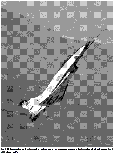
NASA Langley became involved in the X-31 Enhanced Fighter Maneuverability (EFM) program in 1984, when mutual discussions with Rockwell International occurred regarding a fighter configuration capable of highly agile flight at extreme angles of attack. Known as the Super Normal Attitude Kinetic Enhancement (SNAKE) configuration, the design underwent exploratory testing in the Full-Scale Tunnel.[1319] The
early cooperative research study later led to a cooperative project using the Langley Full Scale Tunnel, the Langley Spin Tunnel, and the Langley Jet-Exit Test Facility. After DARPA and the West Germany government formally initiated the X-31 program, Langley and Dryden actively par­ticipated in the development of the configuration and flight tests of two X-31 demonstrators at Dryden from 1992 to 1995.

Подпись: 13In the early SNAKE Langley-Rockwell study, Langley researchers assessed the high-angle-of-attack capabilities of the Rockwell-designed configuration that had been designed using computational methods with minimal use of wind tunnel tests. Preliminary evaluations in the full-scale tunnel disclosed that the configuration was unacceptable, being unsta­ble in pitch, roll, and yaw. Langley’s expertise in high-angle-of-attack stability and control contributed to modifications and revisions of the original configuration, eliminating the deficiencies of the SNAKE design.

Simultaneous with the SNAKE activities, several other events con­tributed to shaping what would become the X-31 program. First, the emerging recognition that thrust vectoring would provide unprece­dented levels of control for precision maneuvering at extreme angles of attack had led to joint Langley-Rockwell studies of jet-exit vanes sim­ilar to those previously discussed for the Navy F-14 experiments and the NASA F/A-18 HARV vehicle. The tests, which were conducted in the Langley Jet-Exit Test Facility, inspired Rockwell to include multi­axis thrust-vectoring paddles in the SNAKE configuration. Free-flight testing of the revised SNAKE configuration provided impressive proof that the vectoring paddles were extremely effective.

The second major activity was the strong advocacy of the West German Messerschmitt-Bolkow-Blohm (MBB) Company that asserted that high levels of agility for poststall flight conditions provided dom­inant capabilities for close-in air combat. With the support of DARPA, the X-31 EFM program was initiated in 1986 with a request that Langley be a major participant in the development program. Using the NASA Langley test facility assets for free-flight model testing, spin testing, and drop-model testing uncovered several critical issues for the configuration.

One issue was the general character of inherent poststall motions that might be encountered in the aircraft flight program. Results indi­cated that the X-31 might have marginal nose-down control for recovery from high-angle-of-attack maneuvers, and that severe unstable wing – rock motions would be exhibited by the configuration, resulting in a violent, disorienting roll departure and an unrecoverable inverted stall

Подпись: The X-31 demonstrated the tactical effectiveness of extreme maneuvers at high angles of attack during flights at Dryden. NASA. Подпись: 13

condition. With these inputs, the X-31 design team worked to configure the flight control system for maximum effectiveness and to prevent the foregoing problems, even without thrust vectoring. The value of these contributions from Langley cannot be understated, but equally impor­tant contributions were to come as the drop-model technique maintained operations during the full-scale aircraft flight-test program.

Flight-testing of the two X-31 aircraft began at Dryden in February 1992 under the direction of an International Test Organization (ITO) that included NASA, the U. S. Navy, the U. S. Air Force, Rockwell, the Federal Republic of Germany, and Deutsche Aerospace (formerly MBB). Two issues were encountered in the flight-test program, resulting in addi­tional test requirements from the supporting team of Langley research­ers. Early in the flight tests, pilots reported marginal nose-down pitch control and said that significant improvements would be necessary if the aircraft were to be considered an efficient weapon system for close – in combat. In a quick-response mode, Langley conducted evaluations of 16 configuration modifications to improve nose-down control in the Full-Scale Tunnel. From these tests, a decision was made to add strakes to the lower aft fuselage, and pilots of subsequent flight tests with the modified airplane reported that the problem was eliminated.

Подпись: 13Another problem encountered in the X-31 flights at extreme angles of attack was the presence of large out-of-trim yawing moments with the potential to overpower corrective inputs from the pilot. After a depar­ture was unexpectedly experienced during a maneuvering flight near an angle of attack of 60 degrees, analysis of the flight records indicated that the departure had been caused by a large asymmetric yawing moment that was much larger than any predicted in subscale wind tunnel testing. The presence of asymmetric moments of this type had been well-known to the aeronautics community, including the fact that the phenomenon might be sensitive to the specific Reynolds number under consider­ation. Experience had shown that, for some configurations, the out-of­trim moments exhibited during subscale model tests might be larger than those exhibited at the full-scale conditions, and for other config­urations, opposite results might occur. In the case of the X-31, the full – scale aircraft exhibited significantly higher values.[1320]

The flight-test team sent an urgent request to Langley for solutions to the problem. Once again, tests in the full-scale tunnel were conducted of a matrix of possible airframe modifications, a candidate solution was identified, and real-time recommendations were made to the ITO. In these tunnel tests, a single nose strake was used to predict the maximum level of asymmetry for the airplane, and the solutions worked for that configuration. A pair of nose strakes designed in the tunnel tests was
implemented and, together with other modifications (grit on the nose boom and slight blunting of the fuselage nose tip), permitted the air­craft flight program to continue. This X-31 experience was noteworthy, in that it demonstrated the need for testing seemingly unimportant details at Reynolds numbers equivalent to flight.

The X-31 EFM program completed an X-plane record of 524 flights with 14 evaluation pilots from the sponsoring organizations.

TERMINAL AREA APPROACH OPERATIONS

The XV-5B demonstrated that lift-fan aircraft are capable of performing steep simulated instrument approaches with up to 20° flight-path angles. Once more, lack of an integrated powered-lift flight control system was the primary cause of adverse handling qualities and operational limitations. The SSTOVLF’s integrated powered-lift system must provide decou­pled flight path control for glide slope tracking where a sin­gle controller, such as a throttle-type lever is used for direct flight-path modulation while airspeed and/or angle-of-attack are held constant. Simulator evaluations of such systems have indicated significant improvements in handling qualities and reductions in pilot workload, an integrated powered-lift sys­tem a must in a single-piloted SSTOVF.

Evaluations of the XV-5B’s ability to perform simulated instrument landing approaches along a 10° glide slope revealed that pilots preferred to approach with a deck-parallel attitude (near-zero angle-of-attack) instead of using deck-level attitude (near 10° angle-of-attack) instead of 15°. Fan-stall boundary and random aerodynamic lift disturbances were cited as the causes.

SSTOVLF designers should encourage the development of lift – fans with increased angle-of-attack capability which would enhance Instrument Meteorological Conditions (IMC) oper­ational capability and improve safety.

Подпись: 14All pilots that flew the XV-5 (the "XV-5 Fan Club”) were of the unanimous opinion that the conversion handling qualities of the Vertifan were completely unsatisfactory for IMC oper­ations. Trying to contend with the large power changes, atti­tude and altitude displacements, and abrupt airspeed changes while trying to fly instruments with the XV-5’s "manual” con­trol system was too much to handle. The enhanced operational flexibility requirement laid on the SSTOVLF requires that it have full IMC operational capability.

Negative, Positive, Helpful, and Harmful

Most lightning forms in the negatively charged region under the base of a thunderstorm, whence negative charge is transferred from the cloud to the ground. This so-called "negative lightning” accounts for over 95 percent of strikes. An average bolt of negative lightning carries an elec­tric current of 30 kA, transferring a charge of 5 coulombs, with energy of 500 megajoules (MJ). Large lightning bolts can carry up to 120 kA and 350 coulombs. The voltage is proportional to the length of the bolt.[117]

Some lightning originates near the top of the thunderstorm in its cirrus anvil, a region of high positive charge. Lightning formed in the upper area behaves similarly to discharges in the negatively charged storm base, except that the descending stepped leader carries a posi­tive charge, while its subsequent ground streamers are negative. Bolts thus created are called "positive lightning,” because they deliver a net positive charge from the cloud to the ground. Positive lightning usually consists of a single stroke, while negative lightning typically comprises two or more strokes. Though less than 5 percent of all strikes consist of positive lightning, it is particularly dangerous. Because it originates in the upper levels of a storm, the amount of air it must burn through to reach the ground is usually much greater. Therefore, its electric field typically is much stronger than a negative strike would be and generates enormous amounts of extremely low frequency (ELF) and VLF waves. Its flash duration is longer, and its peak charge and potential are 6 to 10 times greater than a negative strike, as much as 300 kA and 1 billion volts!

Some positive lightning happens within the parent thunderstorm and hits the ground beneath the cloud. However, many positive strikes occur near the edge of the cloud or may even land more than 10 miles away, where perhaps no one would recognize risk or hear thunder.

Such positive lightning strikes are called "bolts from the blue.” Positive lightning may be the main type of cloud-to-ground during winter months or develop in the late stages of a thunderstorm. It is believed to be responsible for a large percentage of forest fires and power-line damage, and poses a threat to high-flying aircraft. Scientists believe that recently discovered high-altitude discharges called "sprites” and "elves” result from positive lightning. These phenomena occur well above parent thunderstorms, at heights from 18 to 60 miles, in some cases reaching heights traversed only by transatmospheric systems such as the Space Shuttle.

Lightning is by no means a uniformly damaging force. For exam­ple, fires started by lightning are necessary in the life cycles of some plants, including economically valuable tree species. It is probable that, thanks to the evolution and spread of land plants, oxygen concentra­tions achieved the 13-percent level required for wildfires before 420 mil­lion years ago, in the Paleozoic Era, as evinced by fossil charcoal, itself proof of lightning-caused range fires.

In 2003, NASA-funded scientists learned that lightning produces ozone, a molecule composed of three oxygen atoms. High up in the stratosphere (about 6 miles above sea level at midlatitudes), ozone shields the surface of Earth from harmful ultraviolet radiation and makes the land hospitable to life, but low in the troposphere, where most weather occurs, it’s an unwelcome byproduct of manmade pollutants. NASA’s researchers were surprised to find that more low-altitude ozone devel­ops naturally over the tropical Atlantic because of lightning than from the burning of fossil fuels or vegetation to clear land for agriculture.

Outdoors, humans can be injured or killed by lightning directly or indirectly. No place outside is truly safe, although some locations are more exposed and dangerous than others. Lightning has harmed vic­tims in improvised shelters or sheds. An enclosure of conductive mate­rial does, however, offer refuge. An automobile is an example of such an elementary Faraday cage.

Property damage is more common than injuries or death. Around a third of all electric power-line failures and many wildfires result from lightning. (Fires started by lightning are, however, significant in the natural life cycle of forests.) Electrical and electronic devices, such as telephones, computers, and modems, also may be harmed by lightning, when overcurrent surges fritz them out via plug-in outlets, phone jacks, or Ethernet cables.

The Lightning Hazard in Aeronautics and Astronautics: A Brief Synopsis

Since only about one-fourth of discharges reach Earth’s surface, lightning presents a disproportionate hazard to aviation and rocketry. Commercial aircraft are frequently struck by lightning, but airliners are built to reduce the hazard, thanks in large part to decades of NASA research. Nevertheless, almost every type of aircraft has been destroyed or severely damaged by lightning, ranging from gliders to jet airliners. The follow­ing is a partial listing of aircraft losses related to lightning:

• August 1940: a Pennsylvania Central Airlines Douglas DC-3A dove into the ground near Lovettsville, VA, kill­ing all 25 aboard (including Senator Ernest Lundeen of Minnesota), after "disabling of the pilots by a severe lightning discharge in the immediate neighborhood of the airplane, with resulting loss of control.”[118]

• June 1959: a Trans World Airlines (TWA) four-engine Lockheed Starliner with 68 passengers and crew was destroyed near Milan, Italy.

• August 1963: a turboprop Air Inter Vickers Viscount crashed on approach to Lyon, France, killing all 20 on board plus 1 person on the ground.

• December 1963: a Pan American Airlines Boeing 707 crashed at night when struck by lightning over Maryland.

All 82 aboard perished.

• April 1966: Abdul Salam Arif, President of Iraq, died in a helicopter accident, reportedly in a thunderstorm that could have involved lightning.

• April 1967: an Iranian Air Force C-130B was destroyed by lightning near Mamuniyeh. The 23 passengers and crew all died.

• Christmas Eve 1971: a Lockheed Electra of Lmeas Aereas Nacionales Sociedad Anonima (LANSA) was destroyed over Peru with 1 survivor among 92 souls on board.

• May 1976: an Iranian Air Force Boeing 747 was hit during descent to Madrid, Spain, killing all 17 aboard.

• November 1978: a U. S. Air Force (USAF) C-130E was struck by lightning near Charleston, SC, and fatally crashed, with six aboard.

• September 1980: a Kuwaiti C-130 crashed after a light­ning strike near Montelimar, France. The eight-man crew was killed.

• February 1988: a Swearingen Metro operated by Nurnberger Flugdienst was hit near Mulheim, Germany, with all 21 aboard killed.

• January 1995: a Super Puma helicopter en route to a North Sea oil platform was struck in the tail rotor, but the pilot autorotated to a water landing. All 16 people aboard were safely recovered.

• April 1999: a British glider was struck, forcing both pilots to bail; they landed safely.

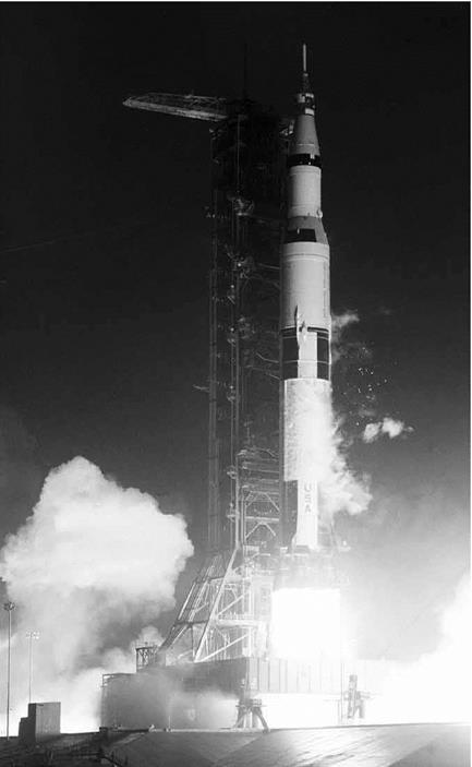
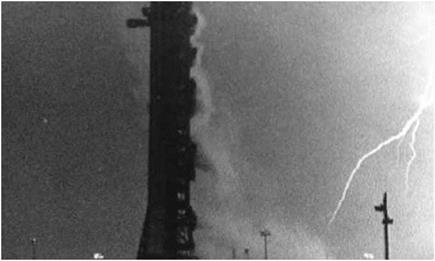
Additionally, lightning posed a persistent threat to rocket-launch operations, forcing extensive use of protective systems such as light­ning rods and "tripwire” devices. These devices included small rockets trailing conductive wires that can trigger premature cloud-to-ground strokes, reducing the risk of more powerful lightning strokes. The clas­sic example was the launch of Apollo 12, on November 14, 1969. "The flight of Apollo 12,” NASA historian Roger E. Bilstein has written, "was electrifying, to say the least.”[119]

During its ascent, it built up a massive static electricity charge that abruptly discharged, causing a brief loss of power. It had been an excep­tionally close call. Earlier, the launch had been delayed while technicians dealt with a liquid hydrogen leak. Had a discharge struck the fuel-air mix of the leak, the conflagration would have been disastrous. Of course, three decades earlier, a form of lightning (a brush discharge, commonly called "St. Elmo’s fire”) that ignited a hydrogen gas-air mix was blamed by investigators for the loss of the German airship Hindenburg in 1937 at Lakehurst, NJ.[120]

Flight Research on Lightning

Benjamin Franklin’s famous kite experiments in the 1750s constituted the first application of lightning’s effect upon "air vehicles.” Though it is uncertain that Franklin personally conducted such tests, they certainly were done by others who were influenced by him. But nearly 200 years passed before empirical data were assembled for airplanes.[121]

Probably the first systematic study of lightning effects on aircraft was conducted in Germany in 1933 and was immediately translated by NASA’s predecessor, the National Advisory Committee on Aeronautics (NACA). German researcher Heinrich Koppe noted diverse opinions on the subject. He cited the belief that any aircraft struck by lightning "would be immediately destroyed or at least set on fire,” and, contrarily, that because there was no direct connection between the aircraft and the ground, "there could be no force of attraction and, consequently, no danger.”[122]

Koppe began his survey detailing three incidents in which "the con­sequences for the airplanes were happily trivial.” However, he expanded the database to 32 occasions in 6 European nations over 8 years. (He searched for reports from America but found none at the time.) By dis­counting incidents of St. Elmo’s fire and a glider episode, Koppe had 29 lightning strikes to evaluate. All but 3 of the aircraft struck had extended trailing antennas at the moment of impact. His conclusion was that wood and fabric aircraft were more susceptible to damage than were metal airframes, "though all-metal types are not immune.” Propellers frequently attracted lightning, with metal-tipped wooden blades being more susceptible than all-metal props. While no fatalities occurred with the cases in Koppe’s studies, he did note disturbing effects upon aircrew, including temporary blindness, short-term stunning, and brief paraly­sis; in each case, fortunately, no lingering effects occurred.[123]

Koppe called for measures to mitigate the effects of lightning strikes, including housing of electrical wires in metal tubes in wood airframes and "lightning protection plates” on the external surfaces. He said radio masts and the sets themselves should be protected. One occasionally overlooked result was "electrostriction,” which the author defined as "very heavy air pressure effect.” It involved mutual attraction of parallel tracks into the area of the current’s main path. Koppe suggested a shield on the bottom of the aircraft to attract ionized air. He concluded: "airplanes are not ‘hit’ by lightning, neither do they ‘accidentally’ get into the path of a stroke. The hits to airplanes are rather the result of a release of more or less heavy electrostatic discharges whereby the airplane itself forms a part of the current path.”[124]

American studies during World War II expanded upon prewar exam­inations in the United States and elsewhere. A 1943 National Bureau of Standards (NBS, now the National Institute for Standards and Technology, NIST) analysis concluded that the power of a lightning bolt was so enormous—from 100 million to 1 billion volts—that there was "no possibility of interposing any insulating barrier that can effectively resist it.” Therefore, aircraft designers needed to provide alternate paths for the discharge via "lightning conductors.”[125] Postwar evaluation reinforced Koppe’s 1933 observations, especially regarding lightning effects upon airmen: temporary blindness (from seconds to 10 minutes), momentary loss of hearing, observation of electrical effects ranging from sparks to "a blinding blue flash,” and psychological effects. The latter were often caused more by the violent sensations attending the entrance of a tur­bulent storm front rather than a direct result of lightning.[126]

Drawing upon British data, the NACA’s 1946 study further detailed atmospheric discharges by altitude bands from roughly 6,500 to 20,500 feet, with the maximum horizontal gradient at around 8,500 feet. Size and configuration of aircraft became recognized factors in lightning, owing to the greater surface area exposed to the atmosphere. Moisture and dust particles clinging to the airframe had greater potential for drawing a light­ning bolt than on a smaller aircraft. Aircraft speed also was considered, because the ram-air effect naturally forced particles closer together.[127]

A Weather Bureau survey of more than 150 strikes from 1935 to 1944 defined a clear "danger zone”: aircraft flying at or near freezing temper­atures and roughly at 1,000 to 2,000 feet above ground level (AGL). The most common factors were 28-34 °F and between 5,000 and 8,000 feet AGL. Only 15 percent of strikes occurred above 10,000 feet.[128]

On February 19, 1971, a Beechcraft B90 King Air twin-turboprop business aircraft owned by Marathon Oil was struck by a bolt of light­ning while descending through 9,000 feet preparatory to landing at Jackson, MI. The strike caused "widespread, rather severe, and unusual” damage. The plane suffered "the usual melted metal and cracked nonmetallic materials at the attachments points” but in addition suffered a local structural implosion on the inboard portions of the lower right wing between the fuselage and right engine nacelle, damage to both flaps, impact-and-crush-type damage to one wingtip at an attachment point, elec­trical arc pitting of flap support and control rod bearings, a hole burned in a ventral fin, missing rivets, and a brief loss of power. "Metal skins were distorted,” NASA inspectors noted, "due to the ‘magnetic pinch effect’ as the lightning current flowed through them.” Pilots J. R. Day and J. W. Maxie recovered and landed the aircraft safely. Marathon received a NASA com­mendation for taking numerous photographs of record and contacting NASA so that a much more detailed examination could be performed.[129]

The jet age brought greater exposure to lightning, prompting further investigation by NOAA (created in 1970 to succeed the Environmental Science Services Administration, which had replaced the Weather Bureau in 1965). The National Severe Storms Laboratory conducted Project Rough Rider, measuring the physical characteristics and effects of thunderstorms, including lightning. The project employed two-seat F-100F and T-33A jets to record the intensity of lightning strikes over Florida and Oklahoma in the mid-1960s and later. The results of the research flights were studied and disseminated to airlines, providing safety guidelines for flight in the areas of thunderstorms.[130]

In December 1978, two Convair F-106A Delta Dart interceptors were struck within a few minutes near Castle Air Force Base (AFB), CA. Both had lightning protection kits, which the Air Force had installed beginning in early 1976. One Dart was struck twice, with both jets sustaining "severe” damage to the Pitot booms and area around the radomes. The protection kits prevented damage to the electrical sys­tems, though subsequent tests determined that the lightning currents well exceeded norms, in the area of 225 kA. One pilot reported that the strike involved a large flash, and that the impact felt "like someone hit the side of the aircraft with a sledgehammer.” The second strike a few minutes later exceeded the first. The report concluded that absent the protection kits, damage to electrical and avionic systems might have been extensive.[131]

Though rare, other examples of dual aircraft strikes have been recorded. In January 1982, a Grumman F-14A Tomcat was en route to the Grumman factory at Calverton, NY, flown by CDR Lonny K. McClung from Naval Air Station (NAS) Miramar, CA, when it was struck by light­ning. The incident offered a dramatic example of how a modern, highly sophisticated aircraft could be damaged, and its safety compromised, by a lightning strike. As CDR McClung graphically recalled:

We were holding over Calverton at 18,000 waiting for a rainstorm to pass. A lightning bolt went down about half a mile in front of us. An arm reached out and zapped the Pitot probe on the nose. I saw the lightning bolt go down and almost as if a time warp, freeze frame, an arm of that lightning came horizontal to the nose of our plane.

It shocked me, but not badly, though it fried every com­puter in the airplane—Grumman had to replace every­thing. Calverton did not open in time for us to recover immediately so we had to go to McGuire AFB (112 miles southwest) and back on the "peanut gyro” since all our displays were fried. With the computers zapped, we had a bit of an adventure getting the plane going again so we could go to Grumman and get it fixed. When we got back to Calverton, one of the linemen told us that the same lightning strike hit a news helo below us. Based on the time, we were convinced it was the same strike that got us. An eerie feeling.[132]

The 1978 F-106 Castle AFB F-106 strikes stimulated further research on the potential danger of lightning strikes on military aircraft, particularly as the Castle incidents involved currents beyond the strength usually encountered.

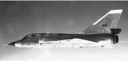
Coincidentally, the previous year, the National Transportation Safety Board had urged cooperative studies among academics, the aviation community, and Government researchers to address the dangers posed to aircraft operations by thunderstorms. Joseph Stickle and Norman Crabill of the NASA Langley Research Center, strongly supported by Allen Tobiason and John Enders at NASA Headquarters, structured a compre­hensive program in thunderstorm research that the Center could pur­sue. The next year, Langley researchers evaluated a lightning location detector installed on an Agency light research aircraft, a de Havilland of Canada DHC-6 Twin Otter. But the most extensive and prolonged study NASA undertook involved, coincidentally, the very sort of aircraft that had figured so prominently in the Castle AFB strikes: a two-seat NF-106B Delta Dart, lent from the Air Force to NASA for research purposes.[133]

The NASA Langley NF-106B lightning research program began in 1980 and continued into 1986. Extensive aerial investigations were under­taken after ground testing, modeling, and simulation.[134] Employing the NF-106B, Langley researchers studied two subjects in particular: the mech­anisms influencing lightning-strike attachments on aircraft and the elec­trical and physical effects of those strikes. Therefore, the Dart was fitted with sensors in 14 locations: 9 in the fuselage plus 3 in the wings and 2 in the vertical stabilizer. In all, the NF-106B sustained 714 strikes during 1,496 storm penetrations at altitudes from 5,000 to 50,000 feet, typically flying within a 150-mile radius of its operating base at Langley.[135] One NASA pilot—Bruce Fisher—experienced 216 lightning strikes in the two – seat Dart. Many test missions involved multiple strikes; during one 1984 research flight at an altitude of 38,000 feet through a thunderstorm, the NF-106B was struck 72 times within 45 minutes, and the peak recorded on that particular test mission was an astounding 9 strikes per minute.[136]

NASA’s NF-106B lightning research program constituted the sin­gle most influential flight research investigation undertaken in atmo­spheric electromagnetic phenomena by any nation. The aircraft, now preserved in an aviation museum, proved one of the longest-lived and most productive of all NASA research airplanes, retiring in 1991. As a team composed of Langley Research Center, Old Dominion University, and Electromagnetic Applications, Inc., researchers reported in 1987:

This research effort has resulted in the first statistical quantification of the electromagnetic threat to aircraft based on in situ measurements. Previous estimates of the in-flight lightning hazard to aircraft were inferred from ground-based measurements. The electromagnetic measurements made on the F-106 aircraft during these strikes have established a statistical basis for determi­nation of quantiles and "worst-case” amplitudes of elec­tromagnetic parameters of rate of change of current and the rate of change of electric flux density. The 99.3 percentile of the peak rate of change of current on the F-106 aircraft struck by lightning is about two and a half times that of previously accepted airworthiness cri­teria. The findings are at present being included in new criteria concerning protection of aircraft electrical and electronic systems against lightning. Since there are at present no criteria on the rate of change of electric flux density, the new data can be used as the basis for new criteria on the electric characteristics of lightning – aircraft electrodynamics. In addition to there being no criteria on the rate of change of electric flux density, there are also no criteria on the temporal durations of this rate of change or rate of change of electric current exceeding a prescribed value. Results on pulse char­acteristics presented herein can provide the basis for this development. The newly proposed lightning crite­ria and standards are the first which reflect actual air­craft responses to lightning measured at flight altitudes.[137]

The data helped shape international certification and design stan­dards governing how aircraft should be shielded or hardened to minimize damage from lightning. Recognizing its contributions to understanding the lightning phenomena, its influence upon design standards, and its ability to focus the attention of lightning researchers across the Federal Government, the Flight Safety Foundation accorded the NF-106B pro­gram recognition as an Outstanding Contribution to Flight Safety for 1989. This did not mark the end of the NF-106B’s electromagnetic research, however, for it was extensively tested at the Air Force Weapons Laboratory at Kirtland AFB, NM, in a cooperative Air Force-NASA study comparing lightning effects with electromagnetic pulses produced by nuclear explosions.[138]

As well, the information developed in F-106B flights led to exten­sion of "triggered” (aircraft-induced) lightning models applied to other aircraft. Based on scaling laws for triggering field levels of differing air­frame sizes and configurations, data were compiled for types as diverse as Lockheed C-130 airlifters and light, business aircraft, such as the Gates (now Bombardier) Learjet. The Air Force operated a Lockheed WC-130 during 1981, collecting data to characterize airborne light­ning. Operating in Florida, the Hercules flew at altitudes between 1,500

Negative, Positive, Helpful, and Harmful

The workhorse General Dynamics NF-106B Delta Dart used by NASA for a range of electro­magnetic studies and research. NASA.

and 18,000 feet, using 11 sensors to monitor nearby thunderstorms. The flights were especially helpful in gathering data on intercloud and cloud-to-ground strokes. More than 1,000 flashes were recorded by ana­log and 500 digitally.[139]

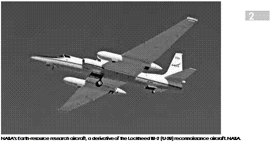
High-altitude research flights were conducted in 1982 with instru­mented Lockheed U-2s carrying the research of the NF-106B and the WC-130 at lower altitudes well into the stratosphere. After a smaller 1979 project, the Thunderstorm Overflight Program was cooperatively spon­sored by NASA, NOAA, and various universities to develop criteria for a lightning mapping satellite system and to study the physics of light­ning. Sensors included a wide-angle optical pulse detector, electric field change meter, optical array sensor, broadband and high-resolution Ebert spectrometers, cameras, and tape recorders. Flights recorded data from Topeka, KS, in May and from Moffett Field, CA, in August. The project col­lected some 6,400 data samples of visible pulses, which were analyzed by NASA and university researchers.[140] NASA expanded the studies to include

flights by an Agency Lockheed ER-2, an Earth-resources research aircraft derived from the TR-2, itself a scaled-up outgrowth of the original U-2.[141]

Complementing NASA’s lightning research program was a coop­erative program of continuing studies at lower altitudes undertaken by a joint American-French study team. The American team consisted of technical experts and aircrew from NASA, the Federal Aviation Administration (FAA), the USAF, the United States Navy (USN), and NOAA, using a specially instrumented American Convair CV-580 twin – engine medium transport. The French team was overseen by the Offices Nationales des Etudes et Recherches Aerospatiales (National Office for Aerospace Studies and Research, ONERA) and consisted of experts and aircrew from the Centre d’Essais Aeronautique de Toulouse (Toulouse Aeronautical Test Center, CEAT) and the l’Armee de l’Air (French Air Force) flying a twin-engine medium airlifter, the C-160 Transall. The Convair was fitted with a variety of external sensors and flown into thunderstorms over Florida in 1984 to 1985 and 1987. Approximately 60 strikes were received, while flying between 2,000 and 18,000 feet. The hits were categorized as lightning, lightning attachment, direct strike, triggered strike, intercepted strike, and electromagnetic pulse. Flight tests revealed a high proportion of strikes initiated by the aircraft itself. Thirty-five of thirty-nine hits on the CV-580 were determined to be aircraft-induced. Further data were obtained by the C-160 with high­speed video recordings of channel formation, which reinforced the opinion that aircraft initiate the lightning. The Transall operated over southern France (mainly near the Pyrenees Mountains) in 1986-1988, and CEAT furnished reports from its strike data to the FAA, and thence to other agencies and industry.[142]
Подпись: NASA's Earth-resource research aircraft, a derivative of the Lockheed TR-2 (U-2R) reconnaissance aircraft. NASA.

Electrodynamic Research Using UAVs

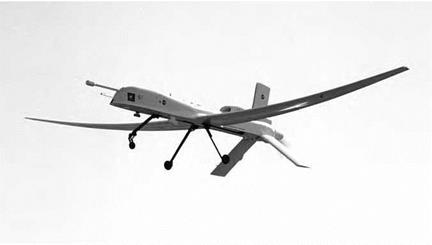
Reflecting their growing acceptance for a variety of military missions, unmanned ("uninhabited”) aerial vehicles (UAVs) are being increasingly used for atmospheric research. In 1997, a Goddard Space Flight Center space sciences team consisting of Richard Goldberg, Michael Desch, and William Farrell proposed using UAVs for electrodynamic studies. Much research in electrodynamics centered upon the direct-current (DC) Global Electric Circuit (GEC) concept, but Goldberg and his colleagues wished to study the potential upward electrodynamic flow from thunderstorms. "We were convinced there was an upward flow,” he recalled over a decade later, "and [that] it was AC.”[143] To study upward flows, Goldberg and his colleagues decided that a slow-flying, high-altitude UAV had advantages of proximity and duration that an orbiting spacecraft did not. They con­tacted Richard Blakeslee at Marshall Space Flight Center, who had a great interest in Earth sciences research. The Goddard-Marshall part-

Negative, Positive, Helpful, and Harmful

NASA Altus 2 electrodynamic research aircraft, a derivative of the General Atomics Predator UAV, in flight on July12, 2002. NASA.

nership quickly secured Agency support for an electrodynamic UAV research program to be undertaken by the National Space Science and Technology Center (NSSTC) at Huntsville, AL. The outcome was Altus, a modification of the basic General Atomics Predator UAV, leased from the manufacturer and modified to carry a NASA electrodynamic research package. Altus could fly as slow as 70 knots and as high as 55,000 feet, cruising around and above (but never into) Florida’s formidable and highly energetic thunderstorms. First flown in 2002, Altus constituted the first time that UAV technology had been applied to study electrody­namic phenomena.[144] Initially, NASA wished to operate the UAV from Patrick AFB near Cape Canaveral, but concerns about the potential dan­gers of flying a UAV over a heavily populated area resulted in switching its operational location to the more remote Key West Naval Air Station. Altus flights confirmed the suppositions of Goldberg and his colleagues, and it complemented other research methodologies that took electric, magnetic, and optical measurements of thunderstorms, gauging lightning

Negative, Positive, Helpful, and Harmful

The launch of Apollo 12 from the John F. Kennedy Space Center in 1969. NASA.

activity and associated electrical phenomena, including using ground – based radars to furnish broader coverage for comparative purposes.[145]

While not exposing humans to thunderstorms, the Altus Cumulus Electrification Study (ACES) used UAVs to collect data on cloud prop­erties throughout a 3- or 4-hour thunderstorm cycle—not always possible with piloted aircraft. ACES further gathered material for three­dimensional storm models to develop more-accurate weather predictions.

Negative, Positive, Helpful, and Harmful

Lightning bolt photographed at the John F. Kennedy Space Center immediately after the launch of Apollo 12 in November 1969. NASA.

Aviation Performance Measuring System: 1996

With the Aviation Safety Reporting System fully operational for two decades, NASA in 1996 once again found itself working with the FAA to gather raw data, process it, and make reports—all in the name of identi­fying potential problems and finding solutions. In this case, as part of a Flight Operations Quality Assurance program that the FAA was working with industry on, the agency partnered with NASA to test a new Aviation Performance Measuring System (APMS). The new system was designed to convert digital data taken from the flight data recorders of participat­ing airlines into a format that could easily be analyzed.[222]

More specifically, the objectives of the NASA-FAA APMS research project was to establish an objective, scientifically and technically sound basis for performing flight data analysis; identify a flight data analysis system that featured an open and flexible architecture, so that it could easily be modified as necessary; and define and articulate guidelines that would be used in creating a standardized database structure that would form the basis for future flight data analysis programs. This stan­dardized database structure would help ensure that no matter which data-crunching software an airline might choose, it would be compat­ible with the APMS dataset. Although APMS was not intended to be a nationwide flight data collection system, it was intended to make avail­able the technical tools necessary to more easily enable a large-scale implementation of flight data analysis.[223]

At that time, commercially available software development was not far enough advanced to meet the needs of the APMS, which sought identification and analysis of trends and patterns in large-scale data­bases involving an entire airline. Software then was primarily written with the needs of flight crews in mind and was more capable of spotting single events rather than trends. For example, if a pilot threw a series of switches out of order, the onboard computer could sound an alarm. But that computer, or any other, would not know how frequently pilots made the same mistake on other flights.[224]

Aviation Performance Measuring System: 1996

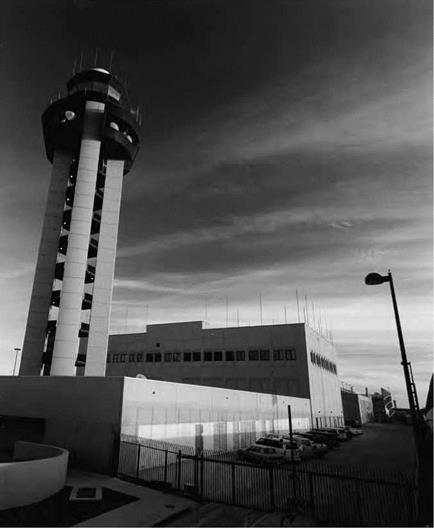
The FAA’s air traffic control tower facility at the Dallas/Fort Worth International Airport is a pop­ular site that the FAA uses for testing new ATC systems and procedures, including new Center TRACON Automation System tools. FAA.

A particularly interesting result of this work was featured in the 1998 edition of NASA’s annual Spinoff publication, which highlights successful NASA technology that has found a new home in the commercial sector:

A flight data visualization system called FlightViz™ has been created for NASA’s Aviation Performance Measuring System (APMS), resulting in a comprehensive flight visualization and

analysis system. The visualization software is now capable of very high-fidelity reproduction of the complete dynamic flight environment, including airport/airspace, aircraft, and cock­pit instrumentation. The APMS program calls for analytic methods, algorithms, statistical techniques, and software for extracting useful information from digitally-recorded flight data. APMS is oriented toward the evaluation of performance in aviation systems, particularly human performance. . . . In fulfilling certain goals of the APMS effort and related Space Act Agreements, SimAuthor delivered to United Airlines in 1997, a state-of-the-art, high-fidelity, reconfigurable flight data replay system. The software is specifically designed to improve airline safety as part of Flight Operations Quality Assurance (FOQA) initiatives underway at United Airlines. . . . Pilots, instructors, human factors researchers, incident investigators, mainte­nance personnel, flight operations quality assurance staff, and others can utilize the software product to replay flight data from a flight data recorder or other data sources, such as a training simulator. The software can be customized to pre­cisely represent an aircraft of interest. Even weather, time of day and special effects can be simulated.[225]

While by no means a complete list of every project NASA and the FAA have collaborated on, the examples detailed so far represent the diverse range of research conducted by the agencies. Much of the same kind of work continued as improved technology, updated systems, and fresh approaches were applied to address a constantly evolving set of challenges.

Langley’s Airborne Trailblazer

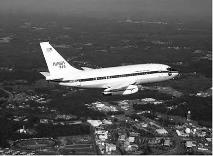
The first Boeing 737 ever built was acquired by NASA in 1974 and modi­fied to become the Agency’s Boeing 737-100 Transport Systems Research Vehicle. During the next 20 years, it flew 702 missions to help NASA advance aeronautical technology in every discipline possible, first as a NASA tool for specific programs and then more generally as a national airborne research facility. Its contributions to the growth in capabil­ity and safety of the National Airspace System included the testing of hardware and procedures using new technology, most notably in the cockpit. Earning its title as an airborne trailblazer, it was the Langley 737 that tried out and won acceptance for new ideas such as the glass

Langley's Airborne Trailblazer

NASA’s Airborne Trailblazer is seen cruising above the Langley Research Center in Virginia. The Boeing 737 served as a flying laboratory for NASA’s aeronautics research for two decades. NASA.

cockpit. Those flat panel displays enabled other capabilities tested by the 737, such as data links for air traffic control communications, the microwave landing system, and satellite-based navigation using the rev­olutionary Global Positioning System.[273]

With plans to retire the 737, NASA Langley in 1994 acquired a Boeing 757-200 to be the new flying laboratory, earning the designa­tion Airborne Research Integrated Experiments System (ARIES). In 2006, NASA decided to retire the 757.[274]

Fatigue Countermeasures Program

NASA Ames Research Center began the Fatigue Countermeasures pro­gram in the 1980s in response to a congressional request to determine if there existed a safety problem "due to transmeridian flying and a poten­tial problem due to fatigue in association with various factors found in air transport operations.”[382] Originally termed the NASA Ames Fatigue/ Jet Lag program, this ongoing program, jointly funded by the FAA, was created to study such issues as fatigue, sleep, flight operations perfor­mance, and the biological clock—otherwise known as circadian rhythms. This research was focused on (1) determining the level of fatigue, sleep loss, and circadian rhythm disruption that exists during flight opera­tions, (2) finding out how these factors affect crew performance, and (3) developing ways to counteract these factors to improve crew alert­ness and proficiency. Many of the findings from this series of field stud­ies, which included such fatigue countermeasures as regular flightcrew naps, breaks, and better scheduling practices, were subsequently adopted by the airlines and the military.[383] This research also resulted in Federal Aviation Regulations that are still in effect, which specify the amount of rest flightcrews must have during a 24-hour period.[384]