Category NASA’S CONTRIBUTIONS TO AERONAUTICS

NACA-NASA and Boundary Layer Control, Externally Blown Flap, and Upper Surface Blowing STOL Research

Short Take-Off and Landing flight research was primarily motivated by the desire of military and civil operators to develop transport air­craft with short-field operational capability typical of low-speed air­planes yet the high cruising speed of jets. For Langley and Ames, it was a natural extension of their earlier boundary layer control (BLC) activ­ity undertaken in the 1950s to improve the safety and operational effi­ciency of military aircraft, such as naval jet fighters that had to land on aircraft carriers, by improving their low-speed controllability and reduc­ing approach and landing speeds.[1338] Indeed, as NACA-NASA engineer-

Подпись: 14
NACA-NASA and Boundary Layer Control, Externally Blown Flap, and Upper Surface Blowing STOL Research

The Stroukoff YC-1 34A was the first large STOL research aircraft flown at NASA’s Ames Research Center. NASA.

historian Edwin Hartman wrote in 1970, "BLC was the first practical step toward achieving a V/STOL airplane.”[1339] This research had demon­strated the benefits of boundary layer flap-blowing, which eventually was applied to operational high-performance aircraft.[1340]

NASA’s first large-aircraft STOL flight research projects involved two Air Force-sponsored experimental transports: a Stroukoff Aircraft Corporation YC-134A and a Lockheed NC-130B Hercules. Both air­craft used boundary layer control over their flaps to augment wing lift.

Подпись: 14
NACA-NASA and Boundary Layer Control, Externally Blown Flap, and Upper Surface Blowing STOL Research

The NC-130B boundary layer control STOL testbed just before touchdown at Ames Research Center; note the wing-pod BLC air compressor, drooped aileron, and flap deflected 90 degrees. NASA.

The YC-134A was a twin-propeller radial-engine transport derived on the earlier Fairchild C-123 Provider tactical transport and designed in 1956. It had drooped ailerons and trailing-edge flaps that deflected 60 degrees, together with a strengthened landing gear. A J30 turbojet com­pressor provided suction for the BLC system. Tested between 1959 and mid-1961, the YC-134A confirmed expectations that deflected propel­ler thrust used to augment a wing’s aerodynamic lift could reduce stall speed. However, in other respects, its desired STOL performance was still limited, indicative of the further study needed at this time.[1341]

More promising was the later NC-130B, first evaluated in 1961 and then periodically afterward. Under an Air Force contract, the Georgia

Division of Lockheed Aircraft Corporation modified a C-130B Hercules tactical transport to a STOL testbed. Redesignated as the NC-130B, it featured boundary layer blowing over its trailing-edge flaps (which could deflect a full 90 degrees down), ailerons (which were also drooped to enhance lift-generation), elevators, and rudder (which was enlarged to improve low-speed controllability). The NC-130 was powered by four Allison T-56-A-7 turbine engines, each producing 3,750 shaft horsepower and driving four-bladed 13.5-foot-diameter Hamilton Standard propel­lers. Two YT-56-A-6 engines driving compressors mounted in outboard wing-pods furnished the BLC air, at approximately 30 pounds of air per second at a maximum pressure ratio varying from 3 to 5. Roughly 75 percent of the air blew over the flaps and ailerons and 25 percent over the tail surfaces.[1342] Thanks to valves and crossover ducting, the BLC air could be supplied by either or both of the BLC engines. Extensive tests in Ames’s 40- by 80-foot wind tunnel validated the ability of the NC-130B’s BLC flaps to enhance lift at low airspeeds, but uncertain­ties remained regarding low-speed controllability. Subsequent flight­testing indicated that such concern was well founded. The NC-130B, like the YC-134A before it, had markedly poor lateral-directional con­trol characteristics during low-speed approach and landing. Ames researchers used a ground simulator to devise control augmentation systems for the NC-130B. Flight test validated improved low-speed lateral – directional control.

Подпись: 14For a corresponding margin above the stall, the handling qualities of the NC-130B in the STOL configuration were changed quite mark­edly from those of the standard C-130 airplane. Evaluation pilots found the stability and control characteristics to be unsatisfactory. At 100,000 pounds gross weight, a conventional C-130B stalled at 80 knots; the BLC NB-130B stalled at 56 knots. Approach speed reduced from 106 knots for the unmodified aircraft to between 67 and 75 knots, though, as one NASA report noted, "At these speeds, the maneuvering capability of the aircraft was severely limited.”[1343] The most seriously affected character-

istics were about the lateral and directional axes, exemplified by prob­lems maneuvering onto and during the final approach, where the pilots found their greatest problem was controlling sideslip angle.[1344]

Landing evaluations revealed that the NC-130B did not conform well to conventional traffic patterns, an indication of what could be expected from other large STOL designs. Pilots were surprised at the length of time required to conduct the approach, especially when the final land­ing configuration was established before turning onto the base leg. Ames researchers Hervey Quigley and Robert Innis noted:

Подпись: 14The time required to complete an instrument approach was even longer, since with this particular ILS system the glide slope was intercepted about 8 miles from touchdown. The requirement to maintain tight control in an instrument landing system (ILS) approach in combination with the aircraft’s unde­sirable lateral-directional characteristics resulted in notice­able pilot fatigue. Two methods were tried to reduce the time spent in the STOL (final landing) configuration. The first and more obvious was suitable for VFR patterns and consisted of merely reducing the size of the pattern, flying the downwind leg at about 900 feet and close abeam, then transitioning to the STOL configuration and reducing speed before turning onto the base leg. Ample time and space were available for maneu­vering, even for a vehicle of this size. The other procedure con­sisted of flying a conventional pattern at high speed (120 knots) with 40° of flap to an altitude of about 500 feet, and then per­forming a maximum deceleration to the approach angle-of – attack using 70° flap and 30° of aileron droop with flight idle power. Power was then added to maintain the approach angle – of-attack while continuing to decelerate to the approach speed.

This procedure reduced the time spent in the approach and generally expedited the operation. The most noticeable adverse effect of this technique was the departure from the original approach path in order to slow down. This effect would com­promise its use on a conventional ILS glide path.[1345]

Flight evaluation of the NC-130B offered important experience and lessons for subsequent STOL development. Again, as Quigley and Innis summarized, it clearly indicated that

The flight control system of an airplane in STOL operation must have good mechanical characteristics (such as low fric­tion, low break-out force, low force gradients) with positive centering and no large non-linearities.

In order to aid in establishing general handling qualities criteria for STOL aircraft, more operational experience was required to help define such items as:

(1) Подпись: 14Minimum airport pattern geometry,

(2) Minimum and maximum approach and climb-out angles,

(3) Maximum cross wind during landings and take-offs, and

(4) All-weather operational limits.17

Overall, Quigley and Innis found that STOL tests of the NC-130B BLC testbed revealed

(1) With the landing configuration of 70° of flap deflection, 30° of aileron droop, and boundary-layer control, the test airplane was capable of landing over a 50-foot obstacle in 1,430 feet at a 100,000 pounds gross weight. The approach speed was 72 knots and the flight-path angle 5° for minimum total distance. The minimum approach speed in flat approaches was 63 knots.

(2) Take-off speed was 65 knots with 40° of flap deflection, 30° of aileron droop, and boundary-layer control at a gross weight of 106,000 pounds. Only small gains in take-off dis­tance over a standard C-130B airplane were possible because of the reduced ground roll acceleration associated with the higher flap deflections.

(3) The airplane had unsatisfactory lateral-directional han­dling qualities resulting from low directional stability and

damping, low side-force variation with sideslip, and low aile­ron control power. The poor lateral-directional characteristics increased the pilots’ workload in both visual and instrument approaches and made touchdowns a very difficult task espe­cially when a critical engine was inoperative.

(4) Neither the airplane nor helicopter military handling quality specifications adequately defined stability and control charac­teristics for satisfactory handling qualities in STOL operation.

(5) Several special operating techniques were found to be required in STOL operations:

(a) Подпись: 14Special procedures are necessary to reduce the time in the STOL configuration in both take-offs and landings.

(b) Since stall speed varies with engine power, BLC effec­tiveness, and flap deflection, angle of attack must be used to determine the margin from the stall.

(6) The minimum control speed with the critical engine inop­erative (either of the outboard engines) in both STOL landing and take-off configurations was about 65 knots and was the speed at which almost maximum lateral control was required for trim. Neither landing approach nor take-off speed was below the minimum control speed for minimum landing or take-off distance.18

During tests with the YC-134B and the NC-130B, NASA research­ers had followed related foreign development efforts, focusing upon two: the French Breguet 941, a four-engine prototype assault trans­port, and the Japanese Shin-Meiwa UF-XS four-engine seaplane, both of which used deflected propeller slipstream to give them STOL perfor­mance. The Shin-Meiwa UF-XS, which a NASA test team evaluated at Omura Naval Air Base in 1964, was built using the basic airframe of a Grumman UF-1 (Air Force SA-16) Albatross seaplane. It was a piloted scale model of a much larger turboprop successor that went on to a
distinguished career as a maritime patrol and rescue aircraft.[1346] However, the Breguet 941 did not, even though both America’s McDonnell com­pany and Britain’s Short firm advanced it for a range of civil and mil­itary applications. A NASA test team was allowed to fly and assess the 941 at the French Centre d’Essais en Vol (the French flight-test center) at Istres in 1963 and undertook further studies at Toulouse and when it came to America at the behest of McDonnell. In conjunction with the Federal Aviation Administration, the team undertook another evalua­tion in 1972 to collect data for a study on developing civil airworthiness criteria for powered-lift aircraft.[1347] The team members found that it had "acceptable performance,” thanks largely to its cross-shafted and oppo­site rotation propellers. The propellers minimized trim changes and asymmetric trim problems in the event of engine failure and ensured no lateral or directional moment changes with variations in airspeed and engine power. But they also found that its longitudinal and lateral – directional stability was "too low for a completely satisfactory rating” and concluded, "More research is required to determine ways to cope with the problem and to adequately define stability and control require­ments of STOL airplanes.”[1348] Their judgment likely matched that of the French, for only four production Breguet 941S aircraft were built; the last of which was retired in 1974. Undoubtedly, however, it was for its time a remarkable and influential aircraft.[1349]

Подпись: 14Another intriguing approach to STOL design was use of lift­enhancing rotating cylinder flaps. Since the early 1920s, researchers in

Подпись: 14Europe and America had recognized that the Magnus effect produced by a rotating cylinder in an airstream could be put to use in ships and airplanes.[1350] Germany’s Ludwig Prandtl, Anton Flettner, and Kurt Frey; the Netherlands E. B. Wolff; and NACA Langley’s Elliott Reid all exam­ined airflow around rotating cylinders and around wings with spanwise cylinders built into their leading, mid, and trailing sections.[1351] All were impressed, for, as Wolff noted succinctly, "The rotation of the cylinder had a remarkable effect on the aerodynamic properties of the wing.”[1352] Flettner even demonstrated a "Rotorschiff” (rotor-ship) making use of two vertical cylinders functioning essentially as rotating sails.[1353] However, because of mechanical complexity, the need for an independent propul­sion source to rotate the cylinder at high speed, and the lack of advan­tage in applying these to aircraft of the interwar era because of their modest performance, none of these systems resulted in more than lab­oratory experiments. However, that changed in the jet era, particularly as aircraft landing and takeoff speeds rose appreciably. In 1963, Alberto Alvarez-Calderon advocated using a rotating cylinder in conjunction with a flap to increase a wing’s lift and reduce its drag. The combination would serve to reenergize the wing’s boundary layer without use of the traditional methods of boundary-layer suction or blowing. Advances in propulsion and high-speed rotating shaft systems, he concluded, "indi­cated to this investigator the need of examining the rotating cylinder as a high lift device for VTOL aircraft.”[1354]

Подпись: 14 NACA-NASA and Boundary Layer Control, Externally Blown Flap, and Upper Surface Blowing STOL Research

In 1971, NASA Ames Program Manager James Weiberg had North American-Rockwell modify the third prototype, YOV-10A Bronco, a small STOL twin-engine light armed reconnaissance aircraft (LARA), with an Alvarez-Calderon rotating cylinder flap system. As well as installing the cylinder, which was 12 inches in diameter, technicians cross-shafted the plane’s two Lycoming T53-L-11 turboshaft engines for increased safety, using the drive train from a Canadair CL-84 Dynavert, a twin-engine tilt rotor testbed. The YOV-10As standard three-bladed propellers were replaced with the four-bladed propellers used on the CL-84, though reduced in diameter so as to furnish adequate clearance of the propeller disk from the fuselage and cockpit. The rotating cylinder, between the wing and flap, energized the plane’s boundary layer by accelerating airflow over the flap. The flaps were modified to entrap the plane’s propeller slipstream, and the combination thus enabled steep approaches and short landings.[1355]

Before attempting flight trials, Ames researchers tested the mod­ified YOV-10A in the Center’s 40- by 80-foot wind tunnel, measuring
changes in boundary layer flow at various rotation speeds. They found that at 7,500 revolutions per minute (rpm), equivalent to a rotational speed of 267.76 mph, the flow remained attached over the flaps even when they were set vertically at 90 degrees to the wing. But in the course of 34 flight-test sorties by North American-Rockwell test pilot Edward Gillespie and NASA pilot Robert Innis, researchers found significant dif­ferences between tunnel predictions and real-world behavior. Flight tests revealed that the YOV-10A had a lift coefficient fully a third greater than the basic YOV-10. It could land with approach speeds of 55 to 65 knots, at descent angles up to 8 degrees, and at flap angles up to 75 degrees. Researchers found that

Подпись: 14Rotation angles to flare were quite large and the results were inconsistent. Sometimes most of the sink rate was arrested and sometimes little or none of it was. There never was any tendency to float. The pilot had the impression that flare capa­bility might be quite sensitive to airspeed (CL)[1356] at flare initia­tion. None of the landings were uncomfortable.[1357]

The modified YOV-10A had higher than predicted lift and down – wash values, likely because of wind tunnel wall interference effects. It also had poor lateral-directional dynamic stability, with occasional lon­gitudinal coupling during rolling maneuvers, though this was a charac­teristic of the basic aircraft before installation of the rotating cylinder flap and had, in fact, forced addition of vertical fin root extensions on production OV-10A aircraft. Most significantly, at increasing flap angles, "deterioration of stability and control characteristics precluded attempts at landing,”[1358] manifested by an unstable pitch-up, "which required full nose-down control at low speeds” and was "a strong function of flap deflection, cylinder operation, engine power and airspeed.”[1359]

As David Few subsequently noted, the YOV-10A’s rotating cylinder flap-test program constituted the first time that: "a flow-entrainment and boundary-layer-energizing device was used for turning the flow down­ward and increasing the wing lift. Unlike all or most pneumatic bound­ary layer control, jet flap, and similar concepts, the mechanically driven rotating cylinder required very low amounts of power; thus there was little degradation to the available takeoff horsepower.”[1360]

Unfortunately, the YOV-10A did not prove to be a suitable research aircraft. As modified, it could not carry a test observer, had too low a wing loading—just 45 pounds per square foot—and so was "easily dis­turbed in turbulence.” Its marginal stability characteristics further hin­dered its research utility, so after this program, it was retired.[1361]

Подпись: 14NASA’s next foray in BLC research was a cooperative program between the United States and Canada that began in 1970 and resulted in NASA’s Augmentor Wing Jet STOL Research Aircraft (AWJSRA) pro­gram. The augmentor wing concept was international in origin, with significant predecessor work in Germany, France, Britain, Canada, and the United States.[1362] The augmentor wing included a blown flap on the trailing edge of a wing, fed by bleed air taken from the aircraft’s engines, accelerating ambient air drawn over the flap and directing it downward to produce lift, using the well-known Coanda effect. Ames researchers conducted early tunnel tests of the concept using a testbed that used a J85 engine powering two compressors that furnished air to the wind tunnel model.[1363] Encouraged, Ames Research Center and Canada’s Department of Industry, Trade, and Commerce (DTIC) moved to collaborate in flying

Подпись: The C-8A augmentor wing testbed on takeoff. NASA. Подпись: 14

a testbed system. Initially, researchers examined putting an augmentor wing on a modified U. S. Army de Havilland CV-7A Caribou twin-piston- engine light STOL transport. But after studying it, they chose instead its bigger turboprop successor, the de Havilland C-8A Buffalo.[1364] Boeing, de Havilland, and Rolls-Royce replaced its turboprop engines with Rolls – Royce Spey Mk 801-SF turbofan engines modified to have the rotating lift nozzle exhausts of the Pegasus engine used in the vectored-thrust P.1127 and Harrier aircraft. They also replaced its high aspect ratio wing with a lower aspect ratio wing with spoilers, blown ailerons, augmentor flaps, and a fixed leading-edge slat. Because it was intended strictly as a low-speed testbed, the C-8A was fitted with a fixed landing gear. As well, it had a long proboscis-like noseboom, which, given the fixed gear and classic T-tail high wing configuration of the basic Buffalo from which it was derived, endowed it with a quirky and somewhat thrown-together appearance. The C-8A project was headed by David Few, with techni-

cal direction by Hervey Quigley, who succeeded Few as manager in 1973. The NASA pilots were Robert Innis and Gordon Hardy. The Canadian pilots were Seth Grossmith, from the Canadian Ministry of Transport, and William Hindson, from the National Research Council of Canada.[1365]

Подпись: 14The C-8A augmentor wing research vehicle first flew on May 1, 1972, and subsequently enjoyed great technical success.[1366] It demonstrated thrust augmentation ratios of 1.20, achieved a maximum lift coefficient of 5.5, flew approach speeds as low as 50 knots, and took off and landed over 50-foot obstructions in as little as 1,000 feet, with ground rolls of only 350 feet. It benefitted greatly from the cushioning phenomena of ground effect, making its touchdowns "gentle and accurate.”[1367] Beyond its basic flying qualities, the aircraft also enabled Ames researchers to continue their studies on STOL approach behavior, flightpath tracking, and the landing flare maneuver. The Ames Avionics Research Branch used it to help define automated landing procedures and evaluated an experimental NASA-Sperry automatic flightpath control system that permitted pilots to execute curved steep approaches and landings, both piloted and automatic. Thus equipped, the C-8A completed its first auto­matic landing in 1975 at Ames’s Crows Landing test facility. Ames oper­ated it for 4 years, after which it returned to Canada, where it continued its own flight-test program.[1368]

Upper surface blowing (USB) constituted another closely related concept for using accelerated flows as a means of enhancing lift pro­duction. Following on the experience with the augmentor wing C-8A testbed, it became NASA’s "next big thing” in transport-related STOL

Подпись: Powered lift concepts. NASA. Подпись: 14

aircraft research. Agency interest in USB was an outgrowth of NACA – NASA research at Langley and Ames on BLC and the engine-bleed-air – fed jet flap, exemplified by tests in 1963 at Langley with a Boeing 707 jet airliner modified to have engine compressor air blown over the wing’s trailing-edge flaps. An Ames 40-foot by 80-foot tunnel research program in 1969 used a British Hunting H.126, a jet-flap research aircraft flight – tested between 1963 and 1967. It used a complex system of ducts and

nozzles to divert over half of its exhaust over its flaps.[1369] As a fully exter­nal system, the upper surface concept was simpler and less structurally intrusive and complex than internally blown systems such as the aug – mentor wing and jet flap. Consequently, it enjoyed more success than these and other concepts that NASA had pursued.[1370]

Подпись: 14In the mid-1950s, Langley’s study of externally blown flaps used in conjunction with podded jet engines, spearheaded by John P. Campbell, had led to subsequent Center research on upper surface blowing, using engines built into the leading edge of an airplane’s wing and exhausting over the upper surface. Early USB results were promising. As Campbell recalled, "The aerodynamic performance was comparable with that of the externally blown flap, and preliminary noise studies showed it to be a potentially quieter concept because of the shielding effect of the wing.” [1371] Noise issues meant little in the 1950s, so further work was dropped. But in the early 1970s, the growing environment noise issue and increased interest in STOL performance led to USB’s resurrection. In particular, the evident value of Langley’s work on externally blown flaps and upper surface blowing intrigued Oran Nicks, appointed as Langley Deputy Director in September 1970. Nicks concluded that upper sur­face blowing "would be an optimum approach for the design of STOL aircraft.”[1372] Nicks’s strong advocacy, coupled with the insight and drive of Langley researchers including John Campbell, Joseph Johnson, and

Arthur Phelps, William Letko, and Robert Henderson, swiftly resulted in modification of an existing externally blown flap (EBF) wind tunnel model to a USB one. The resulting tunnel tests, completed in 1971, confirmed that the USB concept could result in a generous augmentation of lift and low noise. Encouraged, Langley researchers expanded their USB studies using the Center’s special V/STOL tunnel, conducted tests of a much larger USB model in Langley’s Full-Scale Tunnel, and moved on to tests of even larger models derived from modified Cessna 210 and Aero Commander general-aviation aircraft to acquire data more closely matching full-size aircraft. At each stage, wind tunnel testing confirmed that the USB con­cept offered high lifting properties, warranting further exploration.[1373]

Подпись: 14Langley’s research on EBF and USB technology resulted in appli­cation to actual aircraft, beginning with the Air Force’s experimental Advanced Medium STOL Transport (AMST) development effort of the 1970s, a rapid prototyping initiative triggered by the Defense Science Board and Deputy Secretary of Defense David Packard. Out of this came the USB Boeing YC-14 and the EBF McDonnell-Douglas YC-15, evaluated in the 1970s in similar fashion to the Air Force’s Lightweight Fighter (LWF) competition between the General Dynamics YF-16 and Northrop YF-17. Unlike the other evaluation, the AMST program did not spawn a production model of either the YC-14 or YC-15. NASA research benefited the AMST effort, particularly Boeing’s USB YC-14, which first flew in August 1976. It demonstrated extraordinary perfor­mance during flight-testing and a 1977 European tour. The merits of YC-14-style USB impressed the engineers of the Soviet Union’s Antonov design bureau. They subsequently produced a transport, the An-72/74, which bore a remarkable similarity to the YC-14.[1374]

Подпись: 14 NACA-NASA and Boundary Layer Control, Externally Blown Flap, and Upper Surface Blowing STOL Research

In January 1974, NASA launched a study program for a Quiet Short – Haul Research Airplane (QSRA) using USB. The QSRA evolved from earlier proposals by Langley researchers for a quiet STOL transport, the QUESTOL, possibly using a modified Douglas B-66 bomber, an example of which had already served as the basis for an experimental laminar flow testbed, the X-21. However, for the proposed four-engine USB, NASA decided instead to modify another de Havilland C-8, issuing a contract to Boeing as prime contractor for the conversion in 1976.[1375] The QSRA thus benefited fortuitously from Boeing’s work on the YC-14. Again, as with the earlier C-8 augmentor wing, the QSRA had a fixed landing gear and a long conical proboscis. Four 7,860-pound-thrust Avco Lycoming YF102 turbofans furnished the USB. As the slotted flaps lowered, the exhaust followed their curve via Coanda effect, creating additional pro­pulsive lift. First flown in July 1978, the QSRA could take off and land in less than 500 feet, and its high thrust enabled a rapid climbout while making a steep turn over the point from which it became airborne. On approach, its high drag allowed the QSRA to execute a steep approach, which enhanced both its STOL performance and further reduced its

already low noise signature.[1376] It demonstrated high lift coefficients, from 5.5 to as much as 11. Despite a moderately high wing-loading of 80 pounds per square foot, it could fly at landing approach speeds as low as 60 knots. Researchers evaluated integrated flightpath and airspeed controls and displays to assess how precisely the QSRA could fly a pre­cision instrument approach, refined QSRA landing performance to the point where it achieved carrier-like precision landing accuracy, and, in conjunction with Air Force researchers, used the QSRA to help support the development of the C-17 transport, with Air Force and McDonnell – Douglas test pilots flying the QSRA in preparation for their flights in the much larger C-17 transport. Lessons from display development for the QSRA were also incorporated in the Air Force’s MC-130E Combat Talon I special operations aircraft, and the QSRA influenced Japan’s develop­ment of its USB testbed, the ASKA, a modified Kawasaki C-1 with four turbofan engines flown between 1985 and 1989.[1377]

Подпись: 14Not surprisingly, as a result of its remarkable Short Take-Off and Landing capabilities, the QSRA attracted Navy interest in potentially using USB aircraft for carrier missions, such as antisubmarine patrol, airborne early warning, and logistical support. This led to trials of the QSRA aboard the carrier USS Kitty Hawk in 1980. In preparation, Ames researchers undertook a brief QSRA carrier landing flight simulation using the Center’s Flight Simulator for Advanced Aircraft (FSAA), and the Navy furnished a research team from the Carrier Suitability Branch at the Naval Air Test Center, Patuxent River, MD. The QSRA did have one potential safety issue: it could slow without any detectable change in control force or position, taking a pilot unawares. Accordingly, before the carrier landing tests, NASA installed a speed indexer light system that the pilot could monitor while tracking the carrier’s mirror-landing

system Fresnel lens during the final approach to touchdown. The indexer used a standard Navy angle-of-attack indicator modified to show the pilot deviations in airspeed rather than changes in angle of attack. After final reviews, the QSRA team received authorization from both NASA and the Navy to take the plane to sea.

Подпись: 14Sea trials began July 10, 1980, with the Kitty Hawk approximately 100 nautical miles southwest of San Diego. Over 4 days, Navy and NASA QSRA test crews completed 25 low approaches, 37 touch-and-go landings, and 16 full-stop landings, all without using an arresting tail hook during land­ing or a catapult for takeoff assistance. With the carrier steaming into the wind, standard Navy approach patterns were flown, at an altitude of 600 feet above mean sea level (MSL). The initial pattern configuration was USB flaps at 0 degrees and double-slotted wing flaps at 59 degrees. On the down­wind leg, abeam of the bow of the ship, the aircraft was configured to set the USB flaps at 30 degrees and turn on the BLC. The 189-degree turn to final approach to the carrier’s angled flight deck was initiated abeam the round-down of the flight deck, at the stern of the ship. The most demand­ing piloting task during the carrier evaluations was alignment with the deck. This difficulty was caused partially by the ship’s forward motion and consequent continual lateral displacement of the angle deck to the right with the relatively low QSRA approach speeds. In sum, to pilots used to coming aboard ship at 130 knots in high-performance fighters and attack aircraft, the 60-knot QSRA left them with a disconcerting feeling that the ship was moving, so to speak, out from under them. But this was a minor point compared with the demonstration that advanced aerospace tech­nology had reached the point where a transport-size aircraft could land and takeoff at speeds so remarkably slow that it did not need either a tail hook to land or a catapult for takeoff. Landing distance was 650 feet with zero wind over the carrier deck and approximately 170 feet with a 30-knot wind over the deck. Further, the QSRA demonstrated a highly directional noise signature, in a small 35-degree cone ahead of the air­plane, with noise levels of 90 engine-perceived noise decibels at a sideline distance of 500 feet, "the lowest ever obtained for any jet STOL design.”[1378]

The QSRA’s performance made it a crowd pleaser at any airshow where it was flown. Most people had never seen an airplane that large fly with such agility, and it was even more impressive from the cock­pit. One of the QSRA’s noteworthy achievements was appearing at the Paris Air Show in 1983. The flight, from California across Canada and the North Atlantic to Europe, was completed in stages by an airplane having a maximum flying range of just 400 miles. Another was a dem­onstration landing at Monterey airport, where it landed so quietly that airport monitoring microphones failed to detect it.[1379]

Подпись: 14By the early 1980s, the QSRA had fulfilled the expectations its cre­ators, having validated the merits of USB as a means of lift augmentation. Simultaneously, another Coanda-rooted concept was under study, the notion of circulation control around a wing (CCW) via blowing sheet of high-velocity air over a rounded trailing edge. First evaluated on a light general-aviation aircraft by researchers at West Virginia University in 1975 and then refined and tested by a David Taylor Naval Ship Research and Development (R&D) Center team under Robert Englar using a mod­ified Grumman A-6A twin-engine attack aircraft in 1979, CCW appeared as a candidate for addition to the QSRA.[1380] This resulted in a full-scale static ground-test demonstration of USB and CCW on the QSRA aircraft and a proposal to undertake flight trials of the QSRA using both USB and CCW. This, however, did not occur, so QSRA at last retired in 1994. In its more than 15 years of flight research, it had accrued nearly 700 flight hours and over 4,000 STOL approaches and landings, justifying the expectations of those who had championed the QSRA’s development.[1381]

The Aircraft: Tu-144LL SSSR-771114

Подпись: 15The Tu-144 was the world’s first Supersonic Transport, when it took off from Zhukovsky Airfield on December 31, 1968. The design of the air­craft had commenced in early 1963, after the Soviet Union selected the Tupolev Design Bureau for the task. The famed Andrei Tupolev named his son Aleksei Tupolev to be chief designer, and over 1,000 staff mem­bers from other design bureaus were temporarily assigned to Tupolev for this project of national prestige.[1479] For the researchers to evaluate the wing design, a Mig-21 fighter was configured with a scaled model of the wing for in-flight testing. The prototype was completed in the summer of 1968, and in December of that year, Eduard Yelian piloted serial No. SSSR-68001on the Tu-144’s first flight. The Tu-144 first exceeded the speed of sound on June 5, 1969 and achieved speeds in excess of Mach

2.0 on May 26, 1970, in every case just beating Concorde.[1480]

The prototype was displayed at the Paris Air Show for the first time in June 1971. Tragically, the second production aircraft crashed spec­tacularly at the 1973 Paris Air Show. This, in combination with range capabilities only about half of what was expected (2,200 miles versus

4.0 miles), led to Aeroflot (the Soviet national airline company) hav­ing a diminishing interest in the aircraft. Still, a number of significant modifications to the aircraft occurred in the 1970s. The engine nacelles were move farther outboard, necessitating the relocation of the main landing gear to the center of the nacelles, and the original Kuznetsov NK-144 engines were replaced by Kolesov RD-36-51A variants capable of 44,092 pounds of thrust with afterburner. With these engines, the type was redesignated the Tu-144D, and serial No. SSSR-74105, the fifth

Подпись: 15 The Aircraft: Tu-144LL SSSR-771114

production aircraft, first flew with the new engines in November 1974. Cargo and mail service commenced in December 1975, but Aeroflot crews never commanded a single Tu-144. Only Tupolev test pilots ever flew as pilots-in-command. On November 1, 1977, the Tu-144 received its cer­tificate of airworthiness, and passenger service commenced within the Soviet Union. Ten percent larger than the Concorde, the Tu-144 was con­figured with 122 economy and 11 first-class passenger seats. Only two production aircraft served on these passenger routes. The service was terminated May 31, 1978, after the first production Tu-144D crashed on a test flight from Zhukovsky while making an emergency landing because of an in-flight fire. After this crash, four more Tu-144s were produced but were used only as research aircraft. Two continued flying until 1990, including SSSR-771114. The fleet of 16 flyable aircraft accu­mulated 2,556 flights and 4,110 flying hours by 1990.[1481]

After the 1994 U. S.-Russian agreement enabling the HSR Tu-144 flight experiments, SSSR-77114 was selected to be refurbished for flight. The final production aircraft, 77114, was built in 1981 and flew only as a research aircraft, before being placed in storage in 1990. Amazingly, it had only accumulated 83 flight hours at that time. Because the RD-36-51A
engines were no longer being produced or supported, Tupolev switched to the Kuznetsov NK-321 engines from the Tu-160 Blackjack strate­gic bomber as powerplants. [1482] Redesignated the Tu-144LL, or Flying Laboratory, 77114 first flew under the command of Tupolev test pilot Sergei Borisov on November 29, 1996.[1483]

Подпись: 15The Tu-144, although it seems outwardly similar to the Concorde, was actually about 10-percent larger, with a different wing and engine configuration, and with low-speed retractable canard control surfaces that the Concorde lacked. It also solved the many challenges to sustained high-altitude, supersonic flight by different means. Where documentation in the West is complete with Concorde systems and operations manuals and descriptions, NASA and Boeing engineers and pilots could find no English counterparts for the Tu-144. This was due in part to the secrecy of the Tu-144 development in the 1960s and 1970s. Therefore, it is worth briefly describing the systems and operation of the Tu-144 in this essay.

This system description will also give insight into the former Soviet design philosophies. It should be noted that many of the systems on the Tu-144LL were designed in the 1960s, and though completely effective, were somewhat dated by the mid to late 1990s.[1484]

The Tu-144LL is a delta platform, low wing, four engine Supersonic Transport aircraft. Features of interest included a very high coefficient of lift retractable canard and three position-hinged nose structure. The retractable canard is just aft of the cockpit on top of the fuselage and includes both leading – and trailing-edge flaps that deflect when the canard is deployed in low-speed flight. The only aerodynamic con­trol surfaces are 8 trailing-edge elevons, each powered by two actua­tors and upper and lower rudder segments. The nominal cockpit crew

Подпись: 15 The Aircraft: Tu-144LL SSSR-771114

consisted of two pilots, a navigator situated between the two pilots, and a flight engineer seated at a console several feet aft of the navigator on the right side of the aircraft.

The Tu-144LL was 215 feet 6 inches long with a wingspan of 94 feet 6 inches and a maximum height at the vertical stabilizer of 42 feet 2 inches. Maximum takeoff weight was 447,500 pounds, with a maxi­mum fuel capacity of 209,440 pounds.

Quadruple redundant stability augmentation in all axes and an aileron-rudder interconnect characterized a flight control system that provided a conventional aircraft response. Control inceptors included the standard wheel-column and rudder pedals. Pitch and roll rate sen­sor feedbacks passed through a 2.5-hertz (Hz) structural filter to remove aeroservoelastic inputs from the rate signals. Sideslip angle feedback was used to facilitate directional stability above Mach 1.6 or when the canard or landing gear were extended. Similarly, and aileron-rudder interconnect provided additional coordination in roll maneuvers through first-order lag filters between Mach 0.9 and 1.6 and whenever the canard or land­ing gear were extended. A yaw rate sensor signal was fed back through a lead-lag filter to oppose random yaw motions and allow steady turn rates.

Подпись: D= The Aircraft: Tu-144LL SSSR-771114 The Aircraft: Tu-144LL SSSR-771114 Подпись: 15
Подпись: каса
The Aircraft: Tu-144LL SSSR-771114 The Aircraft: Tu-144LL SSSR-771114
The Aircraft: Tu-144LL SSSR-771114
Подпись: pitch
Подпись: piten
The Aircraft: Tu-144LL SSSR-771114
Подпись: wheel gearing
Подпись: 2.5 Hz structural filler
Подпись: St КЖ
Подпись: 0 75
Подпись: column aeanng Подпись: rudder command
Подпись: rudder pedal
Подпись: pedal gearing
Подпись: M < 0.9
Подпись: 3.5 s

The Aircraft: Tu-144LL SSSR-771114sideslip

deg/sec

Schematic of the Tu-144LL flight control system as interpreted by NASA flight control engineer Bruce Jackson from conversations with Tupolev engineers in Zhukovsky, Russia. NASA.

Because the elevons provided both pitch and roll control, a mixer logic limited the combined pitch and roll commands to allowable ele – von travel while favoring pitch commands in the limit cases. Pitch-roll harmony was moderately objectionable by Western standards because of excessive pitch sensitivity contrasted with very weak roll sensitivity.

The installed Kuznetsov NK-321 engines were rated at 55,000 pounds sea level static thrust in afterburner and 31,000 pounds dry thrust. These engines are 5 feet longer and over 1/3 inch wider than the RD-36-51A engines in the Tu-144D, which necessitated extensive modifications to the engine nacelles and nozzle assemblies. The NK-321 engines were mounted 5 feet farther forward in the nacelles, and to accommodate the
larger nozzles, the inboard elevons were modified. The axisymmetric, afterburning, three-stage compressor NK-321 engines were digitally con­trolled, and this necessitated a redesigned flight engineer’s (FE) panel with eight rows of electronic engine parameter displays. The fuel con­trol consisted of a two channel digital electronic control and a backup hydromechanical control. The pilot is only presented with N1 revolu­tions per minute (rpm) indications and throttle command information, which was used to set the desired thrust through power lever angle in degrees (referred to as throttle alpha by Tupolev). All other engine infor­mation, including fuel flows and quantities, oil pressures and temper­atures, and exhaust gas temperatures, was displayed on the FE panel, which is not visible to the pilot. The pilot’s throttles mounted on the cen­ter console had a very high friction level, and in normal situations, the FE set the thrust as commanded by the pilot in degrees throttle alpha. Typical thrust settings in throttle alpha were 72 degrees for maximum dry power, 115 degrees for maximum wet power (afterburner), 98 degrees for Mach 2 cruise, and 59 degrees for supersonic deceleration and ini­tial descent. For takeoff weights less than or equal to 350,000 pounds, 98 degrees throttle alpha was commanded, and for heavier takeoff weights, 115 degrees was used. Operations in the 88- to 95-degree range were avoided for undisclosed reasons.

Подпись: 15A fairly unsophisticated, 2-channel autothrottle (A/T) system was available for approach and landing characterized by a 20-second period and an accuracy of plus or minus 4 mph. The A/T control panel was on the center console, with a left/right selector switch, two selectors for channels, and a rocker switch to command the speed bug on the respec­tive pilot’s airspeed indicator. A throttle "force” of 45 pounds was needed to override the A/T, or individual A/Ts could be deselected by micro­switches in each throttle knob. If two or more were deselected, the sys­tem was disconnected. For the system to be engaged, the FE engaged A/T clutches on the FE throttle quadrant. The A/T could be used from 100 mph up to 250 mph indicated airspeed normally or up to 310 mph under test conditions.

The variable geometry inlets were rectangular, with a moderate fore – to-aft rake. An internal horizontal ramp varied from an up position at speeds below Mach 1.25 to full down at Mach 2. Three shocks were con­tained in the inlet during supersonic flight to slow the inlet flow to sub­sonic speeds; unlike those of other supersonic aircraft, the Tu-144LL’s inlets showed no tendency to experience shock wave-displacing inlet
unstart or other undesired responses during supersonic flight. Even when pilots made full rudder deflections while maintaining a steady heading, generating supersonic sideslips at Mach 2, the inlets and engines contin­ued to function normally. Likewise, when they made 30-degree banked turns and moderately aggressive changes in pitch angle, there were no abnormal results from either the engine or the inlet. This contrasted markedly with the Olympus engines in Concorde. While the Olympus engines were more efficient and were designed in conjunction with the inlets and nozzles to provide a complete, interrelated powerplant sys­tem, the Tu-144LL’s forced use of nonoptimized NK-321 engines required using afterburner to maintain Mach 2 cruise. Of interest was the fact that Concorde’s more efficient engines (Mach 2 cruise was sustained with­out the use of afterburner) were far more susceptible to inlet unstarts and stalls, and as a result, the aggressive engine maneuvers performed in the Tu-144 flight experiment at Mach 2 could not have been accom­plished in the Concorde. The RD-36-51A engines did not require after­burner during supersonic cruise, even though the sea level static thrust rating was lower than that of the NK-321 engines. This was due to the optimized engine/inlet/nozzle system, in which 50 percent of the thrust at supersonic cruise was derived from the inlets and nozzles.[1485]

Подпись: 15The fuel system was comprised of 8 fuel storage areas, including 17 separate tanks. The nomenclature referred to fuel tanks 1 through 8, but only tanks 6, 7, and 8 were single units. Tanks 1, 2, and 8 were bal­ance tanks used to maintain the proper center-of-gravity (CG) location through new, high-capacity fuel transfer jet pumps with peak pressure capacity of 20 atmospheres. These transfer pumps were hydraulically driven and controlled by direct current (DC) power. Fuel boost pumps in each tank were powered by the main alternating current (AC) elec­trical systems. Tank system No. 4 consisted of 6 tanks, 4 of which provide tank-to-engine fuel. A cross-feed capability was used to con­trol lateral balance. Emergency fuel dumping could be accomplished from all fuel tanks. All fuel system information was displayed on the FE panel, and all fuel system controls were accessible only to the FE. Numerous fuel quantity probes were used to provide individual tank sys­tem quantity indications and provide inputs to the CG indicator com-

puter on the FE panel, which continually calculated and displayed the CG location. Proper control of the Tu-144 CG during the transonic through supersonic flight regimes was critical in maintaining aircraft control as the center of lift rapidly changed during sonic transients.

Подпись: 15The Tu-144LL incorporated four hydraulic systems, all of which were connected to separate flight control systems. Up to two hydraulic systems could fail without adversely affecting flight control capability. The flight controls consisted of four elevons per wing and an upper and lower rudder. Each control surface had two actuators with two hydrau­lic channels each so that each hydraulic system partially powered each control surface. The four hydraulic systems were powered by variable displacement engine driven pumps. There were no electrically powered pumps. Engine Nos. 1 and 2 each powered the No. 1 and 2 hydraulic systems, and engine Nos. 3 and 4 each powered the No. 3 and 4 hydrau­lic systems. Systems No. 1 and 2 and systems No. 3 and 4 shared reser­voirs, but dividers in each reservoir precluded a leak in one system from depleting the other. System pressure was nominally between 200 and 220 atmospheres, and a warning was displayed to the pilot if the pres­sure in a system fell below 100 atmospheres. In the event of the loss of 2 hydraulic systems, an emergency hydraulic system powered by an aux­iliary power unit (APU) air-driven pump (or external pneumatic source) was available, but the APU could only be operated below 3-mile altitude (and could not be started above 1.8-mile altitude). For emergency oper­ation of the landing gear (lowering only), a nitrogen system serviced to 150 atmospheres was provided. If one hydraulic system failed, the air­craft was required to decelerate to subsonic speeds. If a second system failed, the aircraft had to be landed as soon as possible.

The landing gear was of the traditional tricycle arrangement, except the Tu-144 had eight wheels on each main truck. Each main landing gear was a single strut with a dual-twin tandem wheel configuration. The landing gear included a ground lock feature that prevented the strut from pivoting about the bogey when on the ground. This resulted in a farther aft ground rotation point, because the aircraft would have to pitch around the aft wheels rather than the strut pivot point, thus pre­venting the aircraft from tilting back on the tail during loading. The redesign of the Tu-144 in the early 1970s moved the engine nacelles farther out on the wings, placing the main landing gear in the middle of the engine inlet ducting. This issue was solved by having the gear bogey rotate 90 degrees about the strut longitudinal axis before retracting

into the tall but narrow wheel well nestled between the adjoining engine inlets.

Подпись: 15The wheel brake system was normally powered by the No. 1 hydraulic system, but a capability existed to interconnect to the No. 2 hydraulic system if necessary. An emergency braking capability using nitrogen gas pressurized to 100 atmospheres was provided. Independent brak­ing levers on both the pilot and copilot’s forward center console areas allowed differential braking with this system. A locked wheel protec­tion circuit prevented application of the brakes airborne above 110 mph airspeed. On the ground, full brake pressure was available 1.5 seconds after full pedal pressure was applied. Above 110 mph on the ground, the brake pressure was reduced to 70 atmospheres. Below 110 mph, brake pressure was increased to 80 atmospheres. A starting brake was avail­able to hold the aircraft in position during engine runups. This was essential, as the engines had to be run for a minimum of 30 minutes on the ground prior to flight. The brakes had to be "burned in” by holding them while taxiing in order to warm them to a minimum temperature to be effective. Furthermore, the braking capability was augmented by a drag parachute on landing to save wear on the tires and brakes.

The Tu-144 was supplied with main AC power at 115 volts and 400 hertz, secondary AC power at 36 volts and 400 Hz, and DC power at 27 volts. Each engine was connected to its respective Integrated Drive Generator (IDG), rated at 120 kilovolt-amperes (KVA) and provid­ing independent AC power to its respective bus. No parallel generator operation was allowed under normal circumstances. Most systems could be powered from more than one bus, and one generator could provide all of the electrical power requirements, except for the canard and inlet anti­ice. A separate APU generator rated at 60 KVA at 400 Hz and provisions for external AC power were provided. The many fuel tank boost pumps were the main electrical power consumers. Other important AC systems were the canard and the retractable nose. The DC system consisted of 4 transformer/rectifiers (TR) and 4 batteries. The normal DC load was 12 kilowatts, and DC power was used for communication units, relays, and signaling devices.

Fire detection sensors and extinguishing agents were available for all engines, the APU, and the 2 cargo compartments. The extinguish­ing agent was contained in 6 canisters of 8-liter capacity each. When an overheat condition was detected, an annunciation was displayed on the FE panel showing the affected area. The pilot received only a "fire”
light on the forward panel, without seeing which area was affected. In the case of APU fire detection, the extinguishing agent was automati­cally released into the APU compartment. In the case of an engine fire, the pilot could do nothing, because all engine fire extinguishing and shutdown controls were on the FE panel.

Подпись: 15The air-conditioning and pressurization system consisted of identi­cal, independent left and right branches. Any one branch could sustain pressurization during high-altitude operations. Nos. 1 and 2 engines and Nos. 3 and 4 engines shared common ducts for their respective bleed air. The right system provided conditioned air to the cockpit and for­ward cabin areas, and the left system furnished conditioned air to the mid and aft passenger cabin areas. The pressurization system provided an air exchange rate of 33 pounds per person per hour, and the total air capacity was 9,000 pounds per hour. Air was not recirculated back into the cabin. The pressurization controller maximum change rate was 0.18 millimeters (mm) of mercury (Hg) per second.

Hot engine bleed air was cooled initially to 374 degrees Fahrenheit (°F) by engine inlet bleed air in an air-air heat exchanger, then com­pressed in an air cycle machine (ACM) to 7.1 atmospheres with an exit temperature of 580 °F, and finally cooled in a secondary heat exchanger to 375 °F or less. If the air temperature were in excess of 200 °F and fuel temperature less than 160 °F, the air would be passed through a fuel-air heat exchanger. Passage through a water separator preceded entry into the expansion turbine of the ACM. Exit temperature from the turbine must be less than or equal to 85 °F, or the turbine would shut down. The FE changed the cockpit and cabin temperature using a hot air mix valve to control the temperature in the supply ducts. An idle descent from high altitude could result in an ACM overheat. In this case, speed must be increased to provide more air for the inlet air heat exchanger. There were four outflow valves on the left side of the fuse­lage and two on the right. The landing gear and brakes were cooled on the ground with air from the outflow valves. The FE controlled the air­conditioning and pressurization system. Desired cabin pressure was set in mm Hg, with 660 mm nominally being set on the ground. During high-altitude cruise, the ambient cabin altitude was nominally 1.7 to

1. 9 miles. Warnings were displayed in the cockpit for cabin altitudes in excess of 2 miles, and 2.5 miles was the maximum.

There was no provision for wing leading-edge anti-icing. Flight­testing of the Tu-144 prototype indicated this was not necessary, because
of the high speeds normally flown by the aircraft and the large degree of leading-edge sweep. The canard, however, was electrically heated for anti-ice protection requiring 20 KVA of AC power. No information was available on engine anti-icing, but the inlets were electrically heated for anti-ice protection.

Подпись: 15Communication capability consisted of standard frequency band UHF and VHF radios and an Interphone Communication System (ICS). A variety of aural tones and messages were available, including mas­ter warning messages, radio altitude calls, and marker beacon tones. The annunciation was in a synthetic female voice format in Russian. Navigation capability consisted of three Inertial Navigation Systems (INS), VOR/DME and ILS receivers, and a Russian version of TACAN. The ILS was not compatible with Western frequency bands. A naviga­tion computer controlled the three INS units. The mutually indepen­dent INS units provided attitude and true heading information to the attitude and horizontal situation indicators provided to each pilot. The No. 3 INS provided inputs to the pilot’s instruments, No. 2 did the same for the copilot’s instruments, and No. 1 could be selected by either pilot if necessary. If the navigation computer failed, the pilot could select raw INS data. Each INS could only accept 20 waypoints. When within 60 miles of the base airport, magnetic heading was used, but outside of that distance, true heading was selected. The crew had the ability to correct the computed position of each INS separately, in 1-mile increments. The Sensitive Pitch Angle Indicator (SPI) mounted above the center glare shield was driven by the No. 3 INS. This provided the pilots with precise pitch angle information necessary for approach and landing. A pilot – designed Vertical Regime Indicator (VRI) was a clever instrument that provided guidance to the pilot for the complex climb and acceleration profiles and descent and deceleration profiles. Concorde, on the other hand, had no such instrument and relied instead charted data.

The autopilot used the same actuators as the manual flight control system and was considered a subsystem of the flight control system. The dampers in all three axes must be operative for the autopilot to be used. The autopilot was a simple two-axis system operated from mode control panels (MCP) on the pilots’ control wheels. Autopilot longitudi­nal and lateral modes included attitude hold, altitude hold, Mach hold, bank-angle hold, heading hold, localizer tracking, and glide-slope track­ing. Each mode was selected by pressing a button on the MCP. As an example of the selector logic, for Mach or bank angle hold to be engaged,

Подпись: 15 Подпись: The sensor arrangement for the six Phase I experiments are shown in this three-view drawing of the Tu-144LL. NASA.

TU-144LL FLIGHT EXPERIMENTS
AND INSTRUMENTATION

attitude hold must first have been selected. Altitude hold could be selected above 1,300-feet altitude but could not be used between 0.85 indicated Mach number (IMN) and 1.2 IMN, because of significant transonic effects. The lateral modes of the autopilot would command roll angles up to 30 degrees, but 25 degrees was the nominal limit. The longitudinal modes operated between 30-degrees nose-up to 11-degrees nose-down and possessed a 10-degree elevon trim range capability. Two autopilot disconnect switches were on each MCP, the left one to disconnect the lateral channel and the right one to disconnect the longitudinal chan­nel. In addition, a red emergency disconnect switch was on each control wheel. The autopilot channels could be manually overridden or discon­nected with a 1-inch pitch input or a 15-degree roll input.

NASA, as Seen by the FAA

Nearly every NASA program related to aviation safety has required the involvement of the FAA. Anything new from NASA that affects—for example, the design of an airliner or the layout of a cockpit panel[185] or the introduction of a modified traffic control procedure that relies on

new technology[186]—must eventually be certified for use by the FAA, either directly or indirectly. This process continues today, extending the leg­acy of dozens of programs that came before—not all of which can be detailed here. But in terms of a historical overview through the eyes of the FAA, a handful of key collaborations with NASA were considered important enough by the FAA to mention in its official chronology, and they are summarized in this section.

Air Traffic Management Research

The work of NASA’s Aeronautics Research Mission Directorate primarily takes place at NASA Field Centers in Virginia, Ohio, and California. It’s at the Ames Research Center at Moffett Field, CA, that a large share of the work to make safer skyways has been managed. Many of the more effective programs to improve the safety and efficiency of the Nation’s air traffic control system began at Ames and continue to be studied.[250]

Seven programs managed within the divisions of Ames’s Air Traffic Management Research office, described in the next section, reveal how NASA research is making a difference in the skies every day.

Early Flight and the Emergence of Human Factors Research

During the early years of 20th century aviation, it became apparent that the ability to maintaining human life and function at high altitude was only one of many human factors challenges associated with pow­ered flight. Aviation received its first big technological boost during the World War I years of 1914-1918.[303] Accompanying this advancement was a new set of human-related problems associated with flight.[304] As a result of the massive, nearly overnight wartime buildup, there were suddenly tens of thousands of newly trained pilots worldwide, flying on a daily basis in aircraft far more advanced than anyone had ever imagined pos­sible. In the latter stages of the war, aeronautical know-how had become so sophisticated that aircraft capabilities had surpassed that of their human operators. These Great War pilots, flying open-cockpit aircraft capable of altitudes occasionally exceeding 20,000 feet, began to routinely suffer from altitude sickness and frostbite.[305] They were also experiencing pressure-induced ear, sinus, and dental pain, as well as motion sickness and vertigo.[306] In addition, these early open-cockpit pilots endured the effects of ear-shattering noise, severe vibration, noxious engine fumes, extreme acceleration or gravitational g forces, and a constant hurricane – force wind blast to their faces.[307] And as if these physical challenges were not bad enough, these early pilots also suffered devastating injuries from crashes in aircraft unequipped with practically any basic safety features.[308] Less obvious, but still a very real human problem, these early high fly­ers were exhibiting an array of psychological problems, to which these stresses undoubtedly contributed.[309] Indeed, though proof of the human limitations in flying during this period was hardly needed, the British found early in the war that only 2 percent of aviation fatalities came at the hands of the enemy, while 90 percent were attributed to pilot defi­ciencies; the remainder came from structural and engine failure, and a variety of lesser causes.[310] By the end of World War I, it was painfully apparent to flight surgeons, psychologists, aircraft designers, and engi­neers that much additional work was needed to improve the human – machine interface associated with piloted flight.

Because of the many flight-related medical problems observed in air­men during the Great War, much of the human factors research accom­plished during the following two decades leading to the Second World War focused largely on the aeromedical aspects of flight. Flight surgeons, physiologists, engineers, and other professionals of this period devoted themselves to developing better life-support equipment and other pro­tective gear to improve safety and efficiency during flight operations. Great emphasis was also placed on improving pilot selection.[311]

Of particular note during the interwar period of the 1920s and 1930s were several piloted high-altitude balloon flights conducted to further investigate conditions in the upper part of the Earth’s atmosphere known as the stratosphere. Perhaps the most ambitious and fruitful of these was the 1935 joint U. S. Army Air Corps/National Geographic Society flight that lifted off from a South Dakota Black Hills natural geological depression known as the "Stratobowl.” The two Air Corps officers, riding in a sealed metal gondola—much like a future space capsule—with a virtual labora­tory full of scientific monitoring equipment, traveled to a record altitude of 72,395 feet.[312] Little did they know it at the time, but the data they col­lected while aloft would be put to good use decades later by human factors scientists in the piloted space program. This included information about cosmic rays, the distribution of ozone in the upper atmosphere, and the spectra and brightness of sun and sky, as well as the chemical composition, electrical conductivity, and living spore content of the air at that altitude.[313]

Although the U. S. Army Air Corps and Navy conducted the bulk of the human factors research during this interwar period of the 1920s and 1930s, another important contributor was the National Advisory Committee for Aeronautics (NACA). Established in 1915, the NACA was actively engaged in a variety of aeronautical research for more than 40 years. Starting only with a miniscule $5,000 budget and an ambitious mission to "direct and conduct research and experimentation in aero­nautics, with a view to their practical solution,”[314] the NACA became one of this country’s leading aeronautical research agencies and remained so up until its replacement in 1958 by the newly established space agency NASA. The work that the NACA accomplished during this era in design engineering and life-support systems, in cooperation with the U. S. mil­itary and other agencies and institutions, contributed greatly to infor­mation and technology that would become vital to the piloted space program, still decades—and another World War—in the future.[315]

Man-Machine Integration Design and Analysis System

NASA jointly initiated this research program in 1980 with the U. S. Army, San Jose State University, and Sterling Software/QSS/Perot Systems, Inc. This ongoing, work-station-based simulation system, which was designed to further develop human performance modeling, links a "virtual human” of a certain physical anthropometric description to a cognitive (visual, auditory, and memory) structure that is representative of human abilities and limitations. MIDAS then uses these human performance models to assess a system’s procedures, displays, and controls. Using these models, procedural and equipment problems can be identified and human – system performance measures established before more expensive test­ing using human subjects.[423] The aim of MIDAS is to "reduce design cycle time, support quantitative predictions of human-system effec­tiveness, and improve the design of crew stations and their associated operating procedures.”[424] These models thus demonstrate the behavior that might be expected of human operators working with a given auto­mated system without the risk and cost of subjecting humans to these conditions. An important aspect of MIDAS is that it can be applied to any human-machine domain once adapted to the particular requirements of that system. It has in fact been employed in the development of such varied functions as establishing baseline performance measures for U. S. Army crews flying Longbow Apache helicopters with and without chem­ical warfare gear, evaluating crew performance/workload issues for steep noise abatement approaches into a vertiport, developing an advanced

NASA Shuttle orbiter cockpit with an improved display/control design, and upgrading emergency 911 dispatch facility and procedures.[425]

Controller-Pilot Data Link Communications

Research for this program, conducted by NASA’s Advanced Transport Operating System (ATOPS), was initiated in the early 1980s to improve the quality of communication between aircrew and air traffic control personnel.[426] With increased aircraft congestion, radio frequency over­load had become a potential safety issue. With so many pilots trying to communicate with ATC at the same time on the same radio frequency, the potential for miscommunication, errors, and even missed transmis­sions had become increasingly great.

One solution to this problem was a two-way data link system. This allows communications between aircrew and controllers to be displayed on computer screens both in the cockpit and at the controller’s station on the ground. Here they can be read, verified, and stored for future ref­erence. Additionally, flightcrew personnel flying in remote locations, well out of radio range, can communicate in real time with ground personnel via computers hooked up to a satellite network. The sys­tem also allows such enhanced capabilities as the transfer of weather data, charts, and other important information to aircraft flying at nearly any location in the world.[427]

Yet another aspect of this system allows computers in aircraft and on the ground to "talk” to one another directly. Controllers can thus arrange closer spacing and more direct routing for incoming and outgoing air­craft. This important feature has been calculated to save an estimated 3,000-6,000 pounds of fuel and up to 8 minutes of flight time on a typi­cal transpacific flight.[428] Digitized voice communications have even been

Man-Machine Integration Design and Analysis System

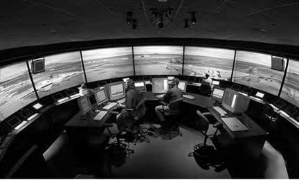
NASA’s Future Flight Central, which opened at NASA Ames Research Center in 1 999, was the first full-scale virtual control tower. Such synthetic vision systems can be used by both aircraft and controllers to visualize clearly what is taking place around them in any conditions. NASA.

added to decrease the amount of aircrew "head-down” time spent read­ing messages on the screen. This system has gained support from both pilots and the FAA, especially after NASA investigations showed that the system decreased communication errors, aircrew workload, and the need to repeat ATC messages.[429]

A Larger Footprint: Reentry Vehicles and Lifting Bodies

The NACA and military visionaries initiated early efforts for the X-15 hypersonic research aircraft, in-house design studies for hypersonic vehi­cles were started at Langley and Ames, and the Air Force began its X-20 Dyna-Soar space plane program. The evolution of long, slender config­urations and others with highly swept lifting surfaces was yet another perturbation of new and unusual vehicles with unconventional aero­dynamic, stability, and control characteristics requiring the use of free – flight models for assessments of flight dynamics.

In addition to the high-speed studies of the X-15 in the Ames super­sonic free-flight facility previously discussed, the X-15 program spon­sored low-speed investigations of free-flight models at Langley in the Full-Scale Tunnel, the Spin Tunnel, and an outdoor helicopter drop model.[495] The most significant contribution of the NASA free-flight tests of the X-15 was confirmation of the effectiveness of the differential tail for control. North American had followed pioneering research at Langley on the use of the tail for roll control. It had used such a design in its YF-107A aircraft and opted to use the concept for the X-15 to avoid aile­rons that would have complicated wing design for the hypersonic air­craft. Nonetheless, skepticism existed over the potential effectiveness of the application until the free-flight tests at Langley provided a dra­matic demonstration of its success.[496]

In the late 1950s, scientists at NASA Ames conducted in-depth studies of the aerodynamic and aerothermal challenges of hypersonic reentry and concluded that blunted half-cone shapes could provide ade­quate thermal protection for vehicle structures while also producing

a significant expansion in operational range and landing options. As interest in the concept intensified following a major conference in 1958, a series of half-cone free-flight models provided convincing proof that such vehicles exhibited satisfactory flight behavior.

The most famous free-flight model activity in support of lifting body development was stimulated by the advocacy and leadership of Dale Reed of the Dryden Flight Research Center. In 1962, Reed became fasci­nated with the lifting body concept and proposed that a piloted research vehicle be used to validate the potential of lifting bodies.[497] He was par­ticularly interested in the flight characteristics of a second-generation Ames lifting body design known as the M2-F1 concept. After Reed’s convincing flights of radio-controlled models of the M2-F1 ranging from kite-like tows to launches from a larger radio-controlled mother ship demonstrated its satisfactory flight characteristics, Reed obtained approval for the construction and flight-testing of his vision of a low – cost piloted unpowered glider. The impact of motion-picture films of Reed’s free-flight model flight tests on skeptics was overwhelming, and management’s support led to an entire decade of highly successful lift­ing body flight research at Dryden.

At Langley, support for the M2-F1 flight program included free – flight tow tests of a model in the Full-Scale Tunnel, and the emergence of Langley’s own lifting body design known as the HL-10 resulted in wind tunnel tests in virtually every facility at Langley. Free-flight test­ing of a dynamic model of the HL-10 in the Full-Scale Tunnel demon­strated outstanding dynamic stability and control to angles of attack as high as 45 degrees, and rolling oscillations that had been exhibited by the earlier highly swept reentry bodies were completely damped for the HL-10 with three vertical fins.[498]

In the early 1970s, a new class of lifting body emerged, dubbed "racehorses” by Dale Reed.[499] Characterized by high fineness ratios, long pointed noses, and flat bottoms, these configurations were much more efficient at hypersonic speeds than the earlier "flying bathtubs.” One Langley-developed configuration, known as the Hyper III, was evalu­ated at Dryden by Reed and his team using free-flight models and the

mother ship test technique. Although the Hyper III was efficient at high speeds, it exhibited a very low lift-to-drag ratio at low speeds requiring some form of variable geometry such as a pivot wing, flexible wing, or gliding parachute.

Reed successfully advocated for a low-cost, 32-foot-long helicopter- launched demonstration vehicle of the Hyper III with a pop-out wing, which made its first flight in 1969. Flown from a ground-based cock­pit, the Hyper III flight was launched from a helicopter at an altitude of 10,000 feet. After being flown in research maneuvers by a research pilot using instruments, the vehicle was handed off to a safety pilot, who safely landed it. Unfortunately, funding for a low-cost piloted project sim­ilar to the earlier M2-F1 activity was not forthcoming for the Hyper III.

Remaining Technical Challenges

Without doubt, the most important technical issues in the application of dynamically scaled free-flight models are the effects of Reynolds num­ber. Although a few research agencies have attempted to minimize these effects by the use of pressurized wind tunnels, a practical approach to free-flight testing without concern for Reynolds number effects has not been identified.

In the author’s opinion, the challenge of eliminating Reynolds num­ber effects in spin studies is worthy of an investigation. In particular, the research community should seriously examine the possibilities of combining recent advances in cryogenic wind tunnel technology, magnetic suspension systems, and other relevant fields in a feasibility study of free-spinning tests at full-scale values of Reynolds number. The obvious issues of cost, operational efficiencies, and value added versus today’s testing would be critical factors in the study, although one would hope that the operational experiences gained in the U. S. and Europe with cryogenic tunnels in recent years might provide some optimism for success.

Other approaches to analyzing and correcting for Reynolds num­ber effects might involve the application of computational fluid dynam­ics (CFD) methods. Although applications of CFD methods to dynamic stability and control issues are in their infancy, one can visualize their use in evaluating the impact of Reynolds number on critical phenom­ena such as the effect of fuselage cross-sectional shape on spin damping.

In summary, the next major breakthroughs in dynamic free-flight model technology should come in the area of improving the prediction of Reynolds number effects. However, to make advances toward this goal will require programmatic commitments similar to the ones made during the past 80 years for the continued support of model testing in the specialty areas discussed herein.

Modern Composite Airplane

Stephen Trimble

Structures and structural materials have undergone progressive refine­ment. Originally, aircraft were fabricated much like ships and complex wooden musical instruments: of wood, wire, and cloth. Then, metal gradually supplanted these materials. Now, high-strength compos­ite materials have become the next generation, allowing for synthetic structures with even better structural properties for much less weight. NASA has assiduously pursued development of composite structures.

HEN THE LOCKHEED MARTIN X-55 advanced composite cargo aircraft (ACCA) took flight early on the morning of June 2, 2009,[642] it marked a watershed moment in a century-long quest to marry the high-strength yet lightweight properties of plastics with the structure required to support a heavily loaded flying vehicle. As the X-55, a greatly modified Dornier 328Jet, headed east from the runway at the U. S. Air Force’s Plant 42 outside Palmdale, CA, it gave the appear­ance of a conventional cargo aircraft. But the X-55’s fuselage structure aft of the fuselage represented perhaps the promising breakthrough in four decades of composite technology development.

The single barrel, measuring 55 feet long by 9 feet wide,[643] revolu­tionizes expectations for structural performance at the same time that it proposes to dramatically reduce manufacturing costs. In the long his­tory of applying composites to aircraft structures, the former seemed always to come at the expense of the latter, or vice versa. Yet the X-55 defies experience, with both aluminum skins and traditional compos­ites. To distinguish it from the aluminum skin of the 328Jet, Lockheed used fewer than 4,000 fasteners to assemble the aircraft with the single­

piece fuselage barrel. The metal 328Jet requires nearly 30,000 fasteners for all the pieces to fit together.[644] Unlike traditional composites, the X-55 did not require hours of time baking in a complex and costly industrial oven called an autoclave. Neither was the X-55 skin fashioned from tex­tile preforms with resins requiring a strictly controlled climate that can be manipulated only within a precise window of time. Instead, Lockheed relied on an advanced composite resin called MTM45-1, an "out – of-autoclave” material flexible enough to assemble on a production line yet strong enough to support the X-55’s normal aerodynamic loads and payload of three 463L-standard cargo pallets.[645]

Modern Composite AirplaneLockheed attributed the program’s success to the fruits of a 10-year program sponsored by the Air Force Research Laboratory called the composites affordability initiative.[646] In truth, the X-55 bears the legacy of nearly a century’s effort to make plastic suitable in terms of both per­formance and cost for serving as a load-bearing structure for large mil­itary and commercial aircraft.

It was an effort that began almost as soon as a method to mass – produce plastic became viable within 4 years after the Wright brothers’ first flight in 1903. In aviation’s formative years, plastics spread from cockpit dials to propellers to the laminated wood that formed the fuse­lage structure for small aircraft. Several decades would pass, however, before the properties of all but the most advanced plastics could be con­sidered for mainstream aerospace applications. The spike in fuel prices of the early 1970s accelerated the search for a basic construction mate­rial for aircraft more efficient than aluminum, and composites finally moved to the forefront. Just as the National Advisory Committee for Aeronautics (NACA) fueled the industry’s transition from spruce to metal in the early 1930s, the National Aeronautics and Space Administration (NASA) would pioneer the progression from all-metal airframes to all­composite material over four decades.

The first flight of the X-55 moved the progression of composite tech­nology one step further. As a reward, the Air Force Research Laboratory announced 4 months later that it would continue to support the X-55
program, injecting more funding to continue a series of flight tests.[647] Where the X-55 technology goes from here can only be guessed.

Avionics and Cockpit Research for Safer General Aviation Operations

Aircraft instrumentation has always been intrinsically related to flight safety. The challenge of blind and bad-weather flying in the 1920s led to development of both radio navigation equipment and tech­niques, and specialized blind-flying instrumentation, typified by the gyro-stabilized artificial horizon, which, like radar later, was one of the few truly transforming instruments developed in the history of flight, for it made possible instrument-only (IFR) flight. Taken together with advances in the Federal airway system, the development of lightweight airborne radars, digital electronics, sophisticated communications, and radar-based and later satellite navigation, as well as access to up-to-date weather information, revolutionized civil and military air operations. Ironically, accident rates remained high, particularly among GA pilots flying single-pilot (SP) aircraft under IFR conditions. By the early 1980s, the National Transportation Safety Board was reporting that "SPIFR” accidents accounted for 79 percent of all IFR-related accidents, with half of these occurring during high-workload landing approaches, total­ing more than 100 serious accidents attributable to pilot error per year.[858] Analysis revealed five major problem areas: controller judgment and response, pilot judgment and response, Air Traffic Control (ATC) intra­facility and interfacility conflict, ATC-pilot communication, and IFR – VFR (instrument flight rules-visual flight rules) conflicts. Common to
all of these were a mix of human error, communications deficiencies, conflicting or complex procedures and rules, and excessive workload. In particular, NASA researchers concluded that "methods, techniques, and systems for reducing work load are drastically needed.”[859]

In the mid-1970s, NASA aeronautics planners had identified "design[ing] avionic systems to more effectively integrate the light air­plane with the air-space system” as a priority, with researchers at Ames Research Center evaluating integration avionic functions with the goal of producing a single system concept.[860] In 1978, faced with the challenge of rising SPIFR accidents, NASA Langley Research Center launched a SPIFR program, holding a workshop in August 1983 at Langley to review and evaluate the progress to date on SPIFR studies and to dis­seminate it to an industry, academic, and governmental audience. The SPIFR program studied in depth the interface of the pilot and airplane, looking at a variety of issues ranging from the tradeoffs between com­plex autopilots and their potential benefits to simulator utility. Overall, researchers found that "[b]ecause of the increase in air traffic and the more sophisticated and complex ground control systems handling this traffic, IFR flight has become extremely demanding, frequently tax­ing the pilot to his limits. It is rapidly becoming imperative that all the pilot’s sensory and manipulative skills be optimized in managing the air­craft systems”; hopefully, they reasoned, the rapid growth in computer capabilities could "enhance single-crewman effectiveness in future air­craft operations and automated ATC systems.”[861] Encouragingly, in part because of NASA research, a remarkable 41-percent decrease in overall GA accidents did occur from the mid-1980s to the late 1990s.[862]

However, all was not well. Indeed, a key goad stimulating NASA’s pur­suit of avionics technology to enhance flight safety (particularly weather safety) was the decline of American General Aviation. In the late 1970s, America’s GA aircraft industry reached the peak of its power: in 1978, manufacturers shipped 17,817 aircraft, and the next year, 1979, the top three manufacturers—Cessna, Beech, and Gates Learjet—had combined sales over $1.8 billion. It seemed poised for even greater success over the next decade. In fact, such did not occur, thanks largely to rapidly rising insurance costs added to aircraft purchase prices, a by-product of a "rash of product liability lawsuits against manufacturers stem­ming from aircraft accidents,” some frivolously alleging inherent design flaws in aircraft that had flown safely for previous decades. Rising air­craft prices cooled any ardor for new aircraft purchases, particularly of single-engine light aircraft (business aircraft sales were affected, but more slowly). Other factors also contributed, including a global reces­sion in the early 1980s, an increase in aircraft leasing and charter aircraft operations (lessening the need for personal ownership), and mergers within the aircraft industry that eliminated some production programs. The number of students taking flight instruction fell by over a third, from 150,000 in 1980 to 96,000 in 1994. That year, GA manufacturers produced just 928 aircraft, representing a production decline of almost 95 percent since the heady days of the late 1970s.[863]

The year 1994 witnessed both the near-extinction of American General Aviation and its fortuitous revival. At the nadir of its fortunes, relief, fortunately, was in hand, thanks to two initiatives launched by Congress and NASA. The first was the General Aviation Revitalization Act (GARA) of 1994, passed by Congress and signed into law in August that year by President William Jefferson Clinton.[864] GARA banned prod­uct liability claims against manufacturers later than 18 years after an aircraft or component first flew. By 1998, the 18-year provision could be applied to the large numbers of aircraft produced in the 1970s, bring­ing relief at last to manufacturers who had been so plagued by legal action that many had actually taken aircraft—including old classics such as the Cessna C-172—out of production.[865] It is not too strong to state that GARA saved the American GA industry from utter extinction, for it brought much needed stability and restored sanity to a litigation process that had gotten out of hand. Thus it constitutes the most signif­icant piece of American aviation legislation passed in the modern era.

But important as well was a second initiative, the establishment by NASA of the AGATE program, a joint NASA-industry-FAA partnership. AGATE existed thanks to the persistency of Bruce Holmes, the Agency’s Assistant Director of Aeronautics, who had vigorously championed it. Functionally organized within NASA’s Advanced Subsonic Technology Project Office, AGATE dovetailed nicely with GARA. It sought to revi­talize GA by focusing on innovative cockpit technologies that could achieve goals of safety, affordability, and ease of use, chief of which was the "Highway in the Sky” (HITS) initiative, which aimed to replace the dial-and-gauge legacy instrument technology of the 1920s with advanced computer-based graphical presentations. As well, it supported crashwor­thiness research. It served as well as single focal point to bring together NASA, industry, Government, and GA community representatives.

AGATE ran from 1994 through 2001, and a key aspect of its success was that it operated under a NASA-unique process, the Joint Sponsored Research Agreement (JSRA), a management process that streamlined research and internal management processes, while accelerating the results of technology development into the private sector. AGATE suf­fered in its early years from "learning problems” with internal communi­cation, with building trust and openness among industry partners more used to seeing themselves as competitors, and with managerial over­sight of its activities. Some participants were disappointed that AGATE never achieved its most ambitious objective, a fully automated aircraft. Others were bothered by the uncertainty of steady Federal support, a characteristic aspect of Federal management of research and develop­ment. But if not perfect—and no program ever is—AGATE proved vital to restoring GA, and as an end-of-project study concluded inelegantly if bluntly, "[a]ccording to participants from all parts of the program, AGATE revitalized an industry that had gone into the toilet.”[866]

The legacy of AGATE is evident in much of NASA’s subsequent avi­onics and cockpit presentation research, which, building upon earlier research, has involved improving a pilot’s situational awareness. Since weather-related accidents account for one-third of all aviation accidents and over one-quarter of all GA accidents, a particular concern is present­ing timely and informative weather information, for example, graphics overlaid on navigational and geographical cockpit displays.[867] Another area of acute interest is improving pilot controllability via advanced flight control technology to close the gap between an automobile-like 2-D control system and the traditionally more complex 3-D aircraft sys­tem and generating a HITS-like synthetic vision capability to enhance flight safety. This, too, is a longstanding concern, related to the handling qualities and flight control capabilities of aircraft so that the pilot can concentrate more on what is going on around the aircraft than having to concentrate on flying it.[868]