Category NASA’S CONTRIBUTIONS TO AERONAUTICS

The Cold War and the Space Age

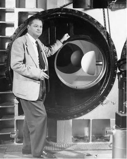
In 1958, NASA was on a firm foundation for hypersonic and space research. Throughout the 1950s, NACA researchers first addressed the challenge of atmospheric reentry with their work on intercontinen­tal ballistic missiles (ICBMs) for the military. The same fundamental design problems existed for ICBMs, spacecraft, interplanetary probes, and hypersonic aircraft. Each of the NASA Centers specialized in a spe­cific aspect of hypersonic and hypervelocity research that resulted from their heritage as NACA laboratories. Langley’s emphasis was in the cre­ation of facilities applicable to hypersonic cruise aircraft and reentry vehicles—including winged reentry. Ames explored the extreme tem­peratures and the design shapes that could withstand them as vehicles

The Cold War and the Space Age

John Becker with his 11-Inch Hypersonic Tunnel of 1947. NASA.

returned to Earth from space. Researchers at Lewis focused on propul­sion systems for these new craft. With the impetus of the space race, each Center worked with a growing collection of hypersonic and hyper­velocity wind tunnels that ranged from conventional aerodynamic facil­ities to radically different configurations such as shock tubes, arc-jets, and new tunnels designed for the evaluation of aerodynamic heating on spacecraft structures.[581]

Airfoil Evolution and Its Application to General Aviation

In the early 1930s, largely thanks to the work of Munk, the NACA had risen to world prominence in airfoil design, such status evident when, in 1933, the Agency released a report cataloging its airfoil research and presenting a definitive guide to the performance and characteristics of a wide range of airfoil shapes and concepts. Prepared by Eastman

N. Jacobs, Kenneth E. Ward, and Robert M. Pinkerton, this document, TR-460, became a standard industry reference both in America and abroad.[785] The Agency, of course, continued its airfoil research in the 1930s, making notable advances in the development of high-speed air­foil sections and low-drag and laminar sections as well. By 1945, as valuable as TR-460 had been, it was now outdated. And so, one of the
most useful of all NACA reports, and one that likewise became a stan­dard reference for use by designers and other aeronautical engineers in airplane airfoil/wing design, was its effective replacement prepared in 1945 by Ira H. Abbott, Albert E. von Doenhoff, and Louis S. Stivers, Jr. This study, TR-824, was likewise effectively a catalog of NACA airfoil research, its authors noting (with justifiable pride) that

Recent information of the aerodynamic characteristics of NACA airfoils is presented. The historical develop­ment of NACA airfoils is briefly reviewed. New data are presented that permit the rapid of the approximate pres­sure distribution for the older NACA four-digital and five­digit airfoils, by the same methods used for the NACA 6-series airfoils. The general methods used to derive the basic thickness forms for NACA 6 and 7 series air­foils together with their corresponding pressure distri­butions are presented. Detailed data necessary for the application of the airfoils to wing design are presented in supplementary figures placed at the end of the paper.

This report includes an analysis of the lift, drag, pitch­ing moment, and critical-speed characteristics of the air­foils, together with a discussion of the effects of surface conditions available data on high-lift devices. Problems associated with the later-control devices, leading edge air intakes, and interference is briefly discussed, together with aerodynamic problems of application.[786]

While much of this is best remembered because of its association with the advanced high-speed aircraft of the transonic and supersonic era, much was as well applicable to new, more capable civil transport and GA designs produced after the war.

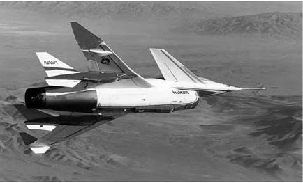
Two key contributions to the jet-age expansion of GA were the super­critical wing and the wingtip winglet, both developments conceived by Richard Travis Whitcomb, a legendary NACA-NASA Langley aerody – namicist who was, overall, the finest aeronautical scientist of the post­Second World War era. More comfortable working in the wind tunnel than sitting at a desk, Whitcomb first gained fame by experimentally investigating the zero lift drag of wing-body combinations through the transonic flow regime based on analyses by W. D. Hayes.[787] His result­ing "Area Rule” for transonic flow represented a significant contribu­tion to the aerodynamics of high-speed aircraft, first manifested by its application to the so-called "Century series” of Air Force jet fighters.[788] Whitcomb followed area rule a decade later in the 1960s and derived the supercritical wing. It delayed the sharp drag rise associated with shock wave formation by having a flattened top with pronounced curva­ture towards its trailing edge. First tested on a modified T-2C jet trainer, and then on a modified transonic F-8 jet fighter, the supercritical wing proved in actual flight that Whitcomb’s concept was sound. This distinc­tive profile would become a key design element for both jet transports and high-speed GA aircraft in the 1980s and 1990s, offering a benefi­cial combination of lower drag, better fuel economy, greater range, and higher cruise speed exemplified by its application on GA aircraft such as the Cessna Citation X, the world’s first business jet to routinely fly faster than Mach 0.90.[789]

The application of Whitcomb’s supercritical wing to General Aviation began with the GA community itself, whose representatives approached Whitcomb after a Langley briefing, enthusiastically endorsing his concept. In response, Whitcomb launched a new Langley program, the Low-and – Medium-Speed Airfoil Program, in 1972. This effort, blending 2-D com­puter analysis and tests in the Langley Low-Turbulence Pressure Tunnel, led to development of the GA(W)-1 airfoil.[790] The GA(W)-1 employed a

Подпись: 8
Airfoil Evolution and Its Application to General Aviation

Low-and-Medium-Speed variants of the GA(W)-1 and -2 airfoil family. From NASA CP – 2046 (1979).

Airfoil Evolution and Its Application to General Aviation

17-percent-thickness-chord ratio low-speed airfoil, offering a beneficial mix of low cruise drag, high lift-to-drag ratios during climbs, high max­imum lift properties, and docile stall behavior.[791] Whitcomb’s team gen­erated thinner and thicker variations of the GA(W)-1 that underwent its initial flight test validation in 1974 on NASA Langley’s Advanced

The Advanced Technology Light Twin-Engine airplane undergoing tests in the Langley 30 ft x 60 ft Full Scale Tunnel. NASA.

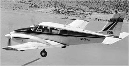
Technology Light Twin (ATLIT) engine airplane, a Piper PA-34 Seneca twin-engine aircraft modified to employ a high-aspect-ratio wing with a GA(W)-1 airfoil with winglets. Testing on ATLIT proved the practical advantages of the design, as did subsequent follow-on ground tests of the ATLIT in the Langley 30 ft x 60 ft Full-Scale-Tunnel.[792]

Subsequently, the NASA-sponsored General Aviation Airfoil Design and Analysis Center (GA/ADAC) at the Ohio State University, led by Dr. Gerald M. Gregorek, modified a single-engine Beech Sundowner light aircraft to undertake a further series of tests of a thinner variant, the GA(W)-2. GA/ADAC flight tests of the Sundowner from 1976-1977 con­firmed that the Langley results were not merely fortuitous, paving the way for derivatives of the GA(W) family to be applied to a range of new aircraft designs starting with the Beech Skipper, the Piper Tomahawk, and the Rutan VariEze.[793]

Following on the derivation of the GA(W) family, NASA Langley researchers, in concert with industry and academic partners, contin­ued refinement of airfoil development, exploring natural laminar flow (NLF) airfoils, previously largely restricted to exotic, smoothly finished sailplanes, but now possible thanks to the revolutionary development of smooth composite structures with easily manufactured complex shapes tailored to the specific aerodynamic needs of the aircraft under devel­opment.[794] Langley researchers subsequently blended their own concep­tual and tunnel research with a computational design code developed at the University of Stuttgart to generate a new natural laminar flow airfoil section, the NLF(1).[795] Like the GA(W) before it, it served as the basis for various derivative sections. After flight testing on various test­beds, it was transitioned into mainstream GA design beginning with a derivative of the Cessna Citation II in 1990. Thereafter, it has become a standard feature of many subsequent aircraft.[796]

The second Whitcomb-rooted development that offered great prom­ise in the 1970s was the so-called winglet.[797] The winglet promised to dra­matically reduce energy consumption and reduce drag by minimizing the wasteful tip losses caused by vortex flow off the wingtip of the air­craft. Though reminiscent of tip plates, which had long been tried over the years without much success, the winglet was a more refined and

Airfoil Evolution and Its Application to General Aviation

The Gates Learjet 28 Longhorn, which pioneered the application of Whitcomb winglets to a General Aviation aircraft. NASA.

better-thought-out concept, which could actually take advantage of the strong flow-field at the wingtip to generate a small forward lift compo­nent, much as a sail does. Primarily, however, it altered the span-wise distribution of circulation along the wing, reducing the magnitude and energy of the trailing tip vortex. First to use it was the Gates Learjet Model 28, aptly named the "Longhorn,” which completed its first flight in August 1977. The Longhorn had 6 to 8 percent better range than pre­vious Lears.[798]

The winglet was experimentally verified for large aircraft applica­tion by being mounted on the wing tips of a first-generation jet transport, the Boeing KC-135 Stratotanker, progenitor of the civil 707 jetliner, and tested at Dryden from 1979-1980. The winglets, designed with a general – purpose airfoil that retained the same airfoil cross-section from root to tip, could be adjusted to seven different cant and incidence angles to enable a variety of research options and configurations. Tests revealed the winglets increased the KC-135’s range by 6.5 percent—a measure of both aerodynamic and fuel efficiency—better than the 6 percent projected by Langley wind tunnel studies and consistent with results obtained with the Learjet Longhorn. With this experience in hand, the winglet was swiftly applied to GA aircraft and airliners, and today, most airlin­ers, and many GA aircraft, use them.[799]

Exploring the Torsionally Free Wing

Aeronautical researchers have long known that low wing load­ing contributes to poor ride quality in turbulence. This problem is compounded by the fact that lightweight aircraft, such as general aviation airplanes, spend a great deal of their flight time at lower altitudes, where measurable turbulence is most likely to occur. One way to improve gust alleviation is through the use of a torsionally free wing, also known as a free wing.

The free-wing concept involves unconventional attachment of a wing to an airplane’s fuselage in such a way that the airfoil is free to pivot about its spanwise axis, subject to aerodynamic pitching moments but otherwise unrestricted by mechanical constraints. To provide static pitch stability, the axis of rotation is located forward of the chordwise aerodynamic center of the wing panel. Angle-of-attack equilibrium is established through the use of a trimming control surface and natural torque from lift and drag. Gust alleviation, and thus improved ride qual­ity, results from the fact that a stable lifting surface tends to maintain a prescribed lift coefficient by responding to natural pitching moments that accompany changes in airflow direction.[923] Use of a free wing offers other advantages as well. Use of full-span flaps permits operation at a higher lift coefficient, thus allowing lower minimum-speed capability. A free sta­bilizer helps eliminate stalls. Use of differentially movable wings instead of ailerons permits improved roll control at low speeds. During take­off, the wing rotates for lift-off, eliminating pitching movements caused by landing-gear geometry issues. Lift changes are accommodated without body-axis rotation. Because of independent attitude control, fuselage pitch can be trimmed for optimum visibility during landing approach. Negative lift can be applied to increase deceleration during

Подпись: Dick Eldredge, left, and Dan Garrabrant prepare the Free-Wing RPRV for flight. NASA. Подпись: 9

landing roll. Fuselage drag can be reduced through attitude trim. Finally, large changes in the center of gravity do not result in changes to longi­tudinal static stability.[924] To explore this concept, researchers at NASA Dryden, led by Shu Gee, proposed testing a radio-controlled model air­plane with a free-wing/free-canard configuration. Quantitative and qual­itative flight-test data would provide proof of the free-wing concept and allow comparison with analytical models. The research team included engineers Gee and Chester Wolowicz of Dryden. Dr. Joe H. Brown, Jr., served as principal investigator for Battelle Columbus Laboratories of Columbus, OH. Professor Gerald Gregorek of Ohio State University’s Aeronautical Engineering Department, along with Battelle’s Richard F. Porter and Richard G. Ollila, calculated aerodynamics and equations of motion. Battelle’s Professor David W. Hall, formerly of Iowa State University, assisted with vehicle layout and sizing.[925] Technicians at Dryden modified a radio-controlled airplane with a 6-foot wingspan to the test configuration. A small free-wing airfoil was rigidly mounted on twin booms forward of the primary flying surface. The ground pilot could change wing lift by actuating a flap on the free wing for longitudinal

control. Elevators provided pitch attitude control, while full-span ailerons were used for roll control.

For data acquisition, the Free-Wing RPRV was flown at low alti­tude in a pacing formation with a ground vehicle. Observers noted the positions of protractors on the sides of the aircraft to indicate wing and canard position relative to the fuselage. Instrumentation in the vehi­cle, along with motion picture film, allowed researchers to record wing angle, control-surface positions, velocity, and fuselage angle relative to the ground. Another airplane model with a standard wing configuration was flown under similar conditions to collect baseline data for comparison with the Free-Wing RPRV performance.[926]

Researchers conducted eight flights at Dryden during spring 1977. They found that the test vehicle exhibited normal stability and con­trol characteristics throughout the flight envelope for all maneuvers performed. Pitch response appeared to be faster than that of a con­ventional airplane, apparently because the inertia of the free-wing assem­bly was lower than that of the complete airplane. Handling qualities appeared to be as good or better than those of the baseline fixed-wing airplane. The investigators noted that separate control of the decoupled fuselage enhanced vehicle performance by acting as pseudo-thrust vectoring. The Free-Wing RPRV had excellent stall/spin characteristics, and the pilot was able to control the aircraft easily under gusty condi­tions. As predicted, center of gravity changes had little or no effect on longitudinal stability.[927] Some unique and unexpected problems were also encountered. When the canard encountered a mechanical trailing – edge position limit, it became aerodynamically locked, resulting in an irreversible stall and hard landing. Increased deflection limits for the free canard eliminated this problem. Researchers had difficulty matching the wing-hinge margin (the distance from the wing’s aerody­namic center to the pivot) and canard control effectiveness. Designers improved handling qualities by increasing the wing hinge margin, the canard area aft of the pivot, and the canard flap area. Canard pivot friction caused some destabilizing effects during taxi, but these abated during takeoff. The ground pilot experienced control difficulty

Подпись: A research pilot controls the DAST vehicle from a ground cockpit. NASA. Подпись: 9

because wing-fuselage decoupling made it difficult to visually judge approach and landing speeds, but it was concluded that this would not be a problem for a pilot flying a full-scale airplane equipped with con­ventional flight instruments.[928]

Feeling the "Need for Speed": Military Requirements in the Atomic Age

Подпись: 10In the 1950s and into the 1960s, the USAF and Navy demanded super­sonic performance from fighters in level flight. The Second World War experience had shown that higher speed was productive in achieving superiority in fighter-to-fighter combat, as well as allowing a fighter to intercept a bomber from the rear. The first jet age fighter combat over Korea with fighters having swept wings had resulted in American air superiority, but the lighter MiG-15 had a higher ceiling and better climb rate and could avoid combat by diving away. When aircraft designers interviewed American fighter pilots in Korea, they specified, "I want to go faster than the enemy and outclimb him.”[1060] The advent of nuclear­armed jet bombers meant that destruction of the bomber by an intercep­tor before weapon release was critical and put a premium on top speed, even if that speed would only be achievable for a short time.

Similarly, bomber experience in World War II had shown that loss rates were significantly lower for very fast bombers, such as the Martin B-26 and the de Havilland Mosquito. The prewar concept of the slow, heavy-gun-studded "flying fortress,” fighting its way to a target with no fighter escort, had been proven fallacious in the long run. The use of B-29s in the Korean war in the MiG-15 jet fighter environment had resulted in high B-29 losses, and the team switched to night bombing, where the MiG-15s were less effective. Hence, the ideal jet bomber would be one capable of flying a long distance, carrying a large payload, and capable of increased speed when in a high-threat zone. The length of the high-speed (and probably supersonic) dash might vary on the threat, combat radius, and fuel capacity of the long-range bomber, but it would likely be a longer distance than the short-legged fighter was capable of at supersonic flight. The USAF relied on the long-range bomber as a primary reason for its independent status and existence; hence, it was
interested in using the turbojet to improve bomber performance and survivability. But supersonic speeds seemed out of the question with the early turbojets, and the main effort was on wringing long range from a jet bomber. Swept thin wings promised higher subsonic cruise speed and increased fuel efficiency, and the Boeing Company took advantage of NACA swept wing research initiated by Langley’s R. T. Jones in 1945 to produce the B-47 and B-52, which were not supersonic but did have the long range and large payloads.[1061]

Подпись: 10The development of more fuel-efficient axial-flow turbojets such as the General Electric J47 and Pratt & Whitney J57 (the first mass – produced jet engine to develop over 10,000 pounds static sea level non­afterburning thrust) were another needed element. Aerial refueling had been tried on an experimental basis in the Second World War, but for jet bombers, it became a priority as the USAF sought the goal of a large-payload jet bomber with intercontinental range to fight the pro­jected atomic third World War. The USAF began to look at a supersonic dash jet bomber now that supersonic flight was an established capabil­ity being used in the fighters of the day. Just as the medium-range B-47 had served as an interim design for the definitive heavy B-52, the ini­tial result was the delta wing Convair B-58 Hustler. The initial designs had struggled with carrying enough fuel to provide a worthwhile super­sonic speed and range; the fuel tanks were so large, especially for low supersonic speeds with their high normal shock drag, that the airplane was huge with limited range and was rejected. Convair adopted a new approach, one that took advantage of its experience with the area rule redesign of the F-102. The airplane carried a majority of its fuel and its atomic payload in a large, jettisonable shape beneath the fuselage, allow­ing the actual fuselage to be extremely thin. The fuselage and the fuse – lage/tank combination were designed in accordance with the area rule. The aircraft employed four of the revolutionary J79 engines being devel­oped for Mach 2 fighters, but it was discovered that with the increased fuel capacity, high installed thrust, and reduced drag at low supersonic Mach numbers, the aircraft could sustain Mach 2 for up to 30 minutes, giving it a supersonic range over 1,000 miles, even retaining the cen­terline store. It could be said that the B-58, although intended to be a

supersonic dash aircraft, became the first practical supersonic cruise aircraft. The B-58 remained in USAF service for less than 10 years for budgetary reasons and its notoriously unreliable avionics. The safety record was not good either, in part because of the difficulty in train­ing pilots to change over from the decidedly subsonic (and huge) B-52 with a crew of six to a "hot ship” delta wing, high-landing-speed aircraft with a crew of three (but only one pilot). Nevertheless, the B-58 fleet amassed thousands of hours of Mach 2 time and set numerous world speed records for transcontinental and intercontinental distances, most averaging 1,000 mph or higher, including the times for slowing for aer­ial refueling. Examples included 4 hours 45 minutes for Los Angeles to New York and back, averaging 1,045 mph, and Los Angeles to New York 1 way in 2 hours 1 minute, at an average speed of 1,214 mph, with 1 refueling over Kansas.

Подпись: 10The later record flight illustrated one of the problems of a supersonic cruise aircraft: heat.[1062] The handbook skin temperature flight limit on the B-58 was 240 degrees Fahrenheit (°F). For the speed run, the limit was raised to 260 degrees to allow Mach 2+, but it was a strict limit; there was concern the aluminum honeycomb skin would debond above that temperature. Extended supersonic flight duration meant that the air­craft structure temperature would rise and eventually stabilize as the heat added from the boundary layer balanced with radiated heat from the hot airplane. The stabilization point was typically reached 20-30 minutes after attaining the cruise speed. The B-58’s Mach 2 speed at 45,000-50,000 feet had reached a structural limit for its aluminum mate­rial; the barrier now was "the thermal thicket”—a heat limit rather the sound barrier.

First Steps in Proving XVS: A View from the Cockpit

Подпись: 11From 1995 through 1999, the XVS element conducted a number of simulator and flight tests of novel concepts using NASA Langley’s and NASA Ames’ flight simulators as well as the Calspan-Air Force Research Laboratory’s NC-131H Total In-Flight Simulator (an extensively modi­fied Convair 580 twin-turboprop transport, with side force controllers, lift flaps, computerized flight controls, and an experimental cockpit) and Langley’s ATOPS Boeing 737.[1158]

In 1995, the first formal test, TSRV.1, was conducted in Langley’s fixed-base Transport Systems Research Vehicle (TSRV) simulator, which replicated the Research Flight Deck (RFD) in Langley’s ATOPS B-737. Under the direction of Principal Investigator Randall Harris, the test was a parametric evaluation of different sensor and HUD presentations of a proposed XVS. A monitor was installed over the copilot’s glare shield to provide simulated video, forward-looking infrared (FLIR), and computer-generated imagery (CGI) for the evaluation. The author had the privilege of undertaking this test, and the following is from the report he submitted after its conclusion:

Approach, flare, and touchdown using 1 of 4 available sensors (2 were FLIR sensors with a simulated selection of the "best” for the ambient conditions) and 1 of 3 HUD presentations making a 3 X 3 test matrix for each scheduled hour long ses­sion. Varying the runways and direction of base to final turns resulted in a total matrix of 81 runs. Each of the 3 pilots com­pleted 63 of the 81 possible runs in the allotted time.[1159]

Commenting on the differences between the leader aircraft flight director and the more traditional HUD/Velocity Vector centered flight director, the author continued:

Some experimentation was performed to best adapt the amount of lead of the leader aircraft. It was initially agreed that a 25 to 15 sec lead worked best for the TSRV simulator.

Подпись: 11The 5 sec lead led to a too high gain task for the lateral axis control system and resulted in chasing the leader continu­ously in a roll PIO state. Adjusting the amount of lead for the leader may need to be revisited in the airplane. A purely per­sonal opinion is that the leader aircraft concept is a higher workload arrangement than a HUD mounted velocity vector centered flight director properly tuned.[1160]

At the same time, a team led by Russ Parrish was developing its own fixed-based simulator intended to support HSR XVS research and devel­opment. Known as Virtual Imaging Simulator for Transport Aircraft Systems (VISTAS), this simulator allowed rapid plug-and-play evaluation of various XVS concepts and became a valuable tool for XVS research­ers and pilots. Over the next 5 years, this simulator evolved through a series of improvements, leading to the definitive VISTAS III configura­tion. Driven by personal computers rather than the Langley simulation facility mainframe computers, and not subject to as stringent review pro­cesses (because of its fixed-base, low-cost concept), this facility became extremely useful and highly productive for rapid prototyping.[1161]

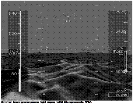
From the ground-based TSRV. 1 test, XVS took to the air with the next experiment, HSR XVS FL.2, in 1996. Using Langley’s venerable ATOPS B-737, FL.2 built upon lessons learned from TSRV.1. FL.2 dem­onstrated for the first time that a pilot could land a transport aircraft using only XVS imagery, with the Langley research pilots flying the air­craft with no external windows in the Research Flight Deck. As well, they landed using only synthetically generated displays, foreshadow­ing future SVS work. Two candidate SVS display concepts were evalu­ated for the first time: elevation-based generic (EBG) and photorealistic. EBG relied on a detailed database to construct a synthetic image of the

Подпись: NASA Langley's Advanced Transport Operating Systems B-737 conducting XVS guided landings. NASA. Подпись: 11

terrain and obstacles. Photorealistic, on the other hand, relied on high – resolution aerial photographs and a detailed database to fuse an image with near-high-resolution photographic quality. These test points were in anticipation of achieving sensor fusion for the HSCT flight deck XVS displays, in which external sensor signals (television, FLIR, etc.) would be seamlessly blended in real time with synthetically derived displays to accommodate surmised varying lighting and visibility conditions. This sensor fusion technology was not achieved during the HSR program, but it would emerge from an unlikely source by the end of the decade.

The second flight test of XVS concepts, known as HSR XVS FL.3, was flown in Langley’s ATOPS B-737 in April 1997 and is illustrative of the challenges in perfecting a usable XVS. Several experiments were accomplished during this flight test, including investigating the effects of nonconformality of the artificial horizon portrayed on the XVS for­ward display and the real-world, out-the-side-window horizon as well as any effects of parallax when viewing the XVS display with a close design eye point rather than viewing the real-world forward scene focused at infinity. Both the Research and Forward Flight Decks (FFD) of the B-737 were highly modified for this test, which was conducted at NASA Wallops Flight Facility (WFF) on Virginia’s Eastern Shore, just south of the Maryland border. Located on the Atlantic coast of the Delmarva

Peninsula, Wallops was situated within restricted airspace and immedi­ately adjoining thousands of square miles of Eastern Seaboard warning areas. The airport was entirely a NASA test and rocket launch facility, complete with sophisticated radar – and laser-tracking capability, control rooms, and high-bandwidth telemetry receivers. Langley flight opera­tions conducted the majority of their test work at Wallops. Every XVS flight test would use WFF.

The modifications to the FFD were summarized in the author’s research notes as follows:

Подпись: 11The aircraft was configured in one of the standard HSR XVS FL.3 configurations including a 2X2 tiled Elmo lipstick cam­era array, a Kodak (Megaplus) high resolution monochrome video camera (1028 x 1028 pixels) mounted below the nose with the tiled camera array, an ASK high resolution (1280 x 1024 pixels) color video projector mounted obliquely behind the co-pilot seat, a Silicon Graphics 4D-440VGXT Skywriter Graphics Workstation, and a custom Honeywell video mixer.

The projector image was focused on a 24 inch by 12 inch white screen mounted 17.5 inches forward of the right cockpit seat Design Eye Position (DEP). Ashtech Differential GPS receiv­ers were mounted on both the 737 and a Beechcraft B-200 tar­get aircraft producing real time differential GPS positioning information for precise inter-aircraft navigation.42

An interesting digression here involves the use of Differential GPS (DGPS) for this experiment. NASA Langley had been a leader in devel­oping Differential GPS technologies in the early 1990s, and the ATOPS B-737 had accomplished the first landing by a transport aircraft using Differential GPS guidance. Plane-plane Differential GPS had been per­fected by Langley researchers in prior years and was instrumental in this and subsequent XVS experiments involving traffic detection using video displays in the flight deck. DGPS could provide real-time relative positions of participating aircraft to centimeter accuracy.

With the conformality and parallax investigations as a background, Langley’s Beechcraft B-200 King Air research support aircraft was
employed for image object detection as a leader aircraft on multiple instrument approaches and as a random traffic target aircraft. FL.3 iden­tified the issue about which a number of XVS researchers and pilots had been concerned about at the XVS Workshop the previous fall: the challenges of seeing a target aircraft in a display. Issues such as pixel per degree resolution, clutter, brightness, sunlight readability, and con­trast were revealed in FL.3. From the flight-test report:

Подпись: 11Unfortunately, the resolution and clarity of the video presen­tation did not allow the evaluation pilot to be able to see the leader aircraft for most of the time. Only if the 737 was flown above the B-200, and it was flying with a dark background behind it, was it readily visible in the display. We closed to 0.6 miles in trail and still had limited success. On final, for exam­ple, the B-200 was only rarely discernible against the runway environment background. The several times that I was able to acquire the target aircraft, the transition from forward display to the side window as I tracked the target was seamless. Most of the time the target was lost behind the horizon line or velocity vector of the display symbology or was not visible due to poor contrast against the horizon. Indeed, even with a bright back­ground with sharp cloud boundaries, the video presentation did not readily distinguish between cloud and sky. . . . Interestingly, the landings are easier this time due, in my opinion, to a per­ceived wider field of view due to the geometry of the arrange­ment in the Forward Flight Deck (FFD) and to the peripheral benefits of the side window. Also, center of percussion effects may have caused false motion cues in the RFD to the extent that it may have affected the landings. The fact that the pilot is quite comfortable in being very confident of his position due to the presence of the side window may have had an effect in reducing the overall mental workload. The conformality differ­ences were not noticeable at 4 degrees, and at 8 degrees, though noticeable and somewhat limiting, successful landings were possible. By adjusting eye height position the pilot could effec­tively null the 0 and 4 degree differences.[1162]

Подпись: 11 Подпись: Convair NC-131H Total In-Flight Simulator used for SVS testing. USAF.

Another test pilot on this experiment, Dr. R. Michael Norman, dis­cussed the effects of rain and insects on the XVS sensors and displays. His words also illustrate the great risks taken by the modern test pilot in the pursuit of knowledge:

Aerodynamics of the flat, forward facing surface of the camera mount enclosure resulted in static positioning of water droplets which became deposited on the aperture face. The relative size of the individual droplets was large and obtrusive, and once they were visible, they generally stayed in place. Just prior to touch­down, a large droplet became visually superimposed with the velocity vector and runway position, which made lineup cor­rections and positional situational awareness extremely diffi­cult. Discussions of schemes to prevent aperture environmental contamination should continue, and consideration of incorpo­ration in future flight tests should be made. During one of the runs, a small flying insect appeared in the cockpit. The shadow of this insect amplified its apparent size on the screen, and was somewhat distracting. Shortly thereafter, it landed on the screen, and continued to be distracting. The presence of flying insects in the cockpit is an issue with front projected displays.44

Clearly, important strides toward a windowless flight deck had been achieved by FL.3, but new challenges had arisen as well. Recognizing the coupling between flight control law development and advanced flight displays, the GFC and Flight Deck ITD Teams planned a joint test in 1998 on a different platform, the Air Force Research Laboratory- Calspan NC-131H Total In-Flight Simulator aircraft.

Подпись: 11TIFS, which was retired to the Air Force Museum a decade after­ward, was an exotic-looking, extensively modified Convair 580 twin – engine turboprop transport that Calspan had converted into an in-flight simulator, which it operated for the Air Force. Unique among such sim­ulators, the TIFS aircraft had a simulation flight deck extending in front of and below the normal flight deck. Additionally, it incorporated two large side force controllers on each wing for simulation fidelity, mod­ified flaps to permit direct lift control, and a main cabin with comput­ers and consoles to allow operators and researchers to program models of different existing or proposed aircraft for simulation. TIFS operated on the model following concept, in which the state vector of TIFS was sampled at a high rate and compared with a model of a simulated air­craft. If TIFS was at a different state than the model, the flight con­trol computers on TIFS corrected the TIFS state vector through thrust, flight controls, direct lift control, and side force control to null all the six degree-of-freedom errors. The Simulation Flight Deck (SFD) design was robust and allowed rapid modification to proposed design specifications.

Undertaken from November 1998 through February 1999, the FL.4 HSR experiment combined XVS and GFC experimental objectives. The SFD was configured with a large cathode ray tube mounted on top of the research pilot’s glare shield, simulating a notional HSR virtual forward window. Head-down PFD and NAV display completed the simulated HSR flight deck. XVS tests for FL.4 included image object detection and dis­play symbology evaluation. The generic HSR control law was used for the XVS evaluation. A generic XVS symbology suite was used for the GFC experiments flown out of Langley and Wallops. Langley research­ers Lou Glaab and Lynda Kramer led the effort, with assistance from the author (who served as Langley HSR project pilot), Calspan test pilot Paul Deppe (among others), and Boeing test pilot Dr. Michael Norman (who was assigned to NASA Langley as a Boeing interface for HSR).

The success of FL.4, combined with some important lessons learned, prepared the way for the final and most sophisticated of the HSR flight tests: FL.5, flown at Langley, Wallops, and Asheville, NC,

Подпись: USAF/Calspan NC-1 31 H The Total In-Flight Simulator on the ramp at Asheville, NC, with the FL.5 crew. Note the simulation flight deck in the extended nose. NASA.
from September through November 1999. Reprising their FL.4 efforts, Langley’s Lou Glaab and Lynda Kramer led FL.5, with valuable assis­tance from Calspan’s Randall E. Bailey, who would soon join the Langley SVS team as a NASA researcher. Russell Parrish also was an indispens­able presence in this and subsequent SVS tests. His imprint was felt throughout the period of focused SVS research at NASA.

With the winding down of the HSR program in 1999, the phase of SVS research tied directly to the needs of a future High-Speed Civil Transport came to an end. But before the lights were turned out on HSR, FL.5 provided an apt denouement and fitting climax to a major program that had achieved much. FL.4 had again demonstrated the difficulty in image object detection using monitors or projected displays. Engineers surmised that a resolution of 60 pixels per degree would be necessary for acceptable performance. The requirement for XVS to be capable of providing traffic separation in VMC was proving onerous. For FL.5, a new screen was used in TIFS. This was another rear projection device, providing a 50-degree vertical by 40-degree horizontal field of view (FOV). Adequate FOV parameters had been and would continue to be a topic of study. A narrow FOV (30 degrees or less), while providing good
resolution, lacked accommodation for acceptable situation awareness. As FOVs became wider, however, distortion was inevitable, and resolu­tion became an issue. The FL.5 XVS display, in addition to its impres­sive FOV, incorporated a unique feature: a high-resolution (60 pixels per degree) inset in the center of the display, calibrated appropriately along an axis to provide the necessary resolution for the flare task and traffic detection. The XVS team pressed on with various preparatory check­outs and tests before finally moving on to a terrain avoidance and traf­fic detection test with TIFS at Asheville, NC.

Подпись: 11Asheville was selected because of the terrain challenges it offered and the high-fidelity digital terrain database of the terminal area pro­vided by the United States Geological Survey. These high-resolution ter­minal area databases are more common now, but in 1999, they were just becoming available. This database allowed the TIFS XVS to pro­vide high-quality head-down PFD SVS information. This foreshadowed the direction Langley would take with FL.5, when XVS gave way to SVS displays incorporating the newer databases. In his FL.5 research notes of the time, the author reflected on the XVS installation, which was by then quite sophisticated:

The Primary XVS Display (PXD) consisted of three tiled pro­jections, an upper, a lower, and a high resolution inset display.

The seams between each projection were noticeable, but were not objectionable. The high resolution inset was designed to approach a resolution of about 60 pixels per degree in the ver­tical axis and somewhat less than that in the horizontal axis.

It is my understanding that this degree of resolution was not actually achieved. The difference in resolution between the high resolution inset and the surround views was not objec­tionable and did not detract from the utility of any of the dis­plays. Symbology was overwritten on all the PXD displays, but at times there was not a perfect match between the sur­rounds and the high resolution inset resulting in some dupli­cated symbology or some occulted symbology. An inboard field-of-view display (IFOV) was also available to the pilot with about the same resolution of the surround views. This also had symbology available.

The symbology consisted of the down selected HSR min­imal symbology set and target symbology for the PXD and a

horizon line, heading marks, and target symbology for the IFOV display. The target symbology consisted of a blue dia­mond with accompanying digital information (distance, alti­tude and altitude trend) placed in the relative position on the PXD or IFOV display that the target would actually be located. Unfortunately, due to several unavoidable transport delays, the target symbology lagged the actual target, especially in high track crossing angle situations. For steady relative bearing situ­ations, the symbology worked well in tracking the target accu­rately. Occasionally, the target symbology would obscure the target, but a well conceived PXD declutter feature corrected this.

Подпись: 11The head down displays available to the pilot included a fairly standard electronic Primary Flight Display (PFD) and Navigation Display (ND). The ND was very useful to the pilot from a strategic perspective in providing situation awareness (SA) for target planning. The PXD provided more of a tactical SA for traffic avoidance. TCAS, Radar, Image Object Detection (IOD), and simulated ADSB targets were displayed and could be brought up to the PXD or IFOV display through a touch screen feature. This implementation was good, but at times was just a little difficult to use. Variable ranges from 4 to 80 miles were pilot selectable through the touch screen. In the past sunlight intrusion in the cockpit had adversely affected both the head up and head down displays. The addition of shaded window liners helped to correct this problem, and sun shafting occur­rences washing out the displays were not frequent.45

The accompanying figure shows the arrangement of XVS displays in the SFD of the TIFS aircraft for the FL.5 experiment.

The author’s flight-test report concluded:

Based on XVS experience to date, it is my opinion that the current state of the art for PXD technologies is insufficient to justify a "windowless” cockpit. Improvements in contrast, res­olution, and fields of view for the PXD are required before this concept can be implemented. . . . A visual means of verifying

Подпись: The XVS head-up and head-down displays used in the FL.5 flight test. NASA. Подпись: 11

the accuracy of the navigation and guidance information pre­sented to the pilot in an XVS configured cockpit seems man­datory. That being said, the use of symbology on the PXD and Nav Display for target acquisition provides the pilot with a sig­nificant increase in both tactical and strategic situation aware­ness. These technologies show huge potentials for use both in the current subsonic fleet as well as for a future HSCT.[1163]

Though falling short of fully achieving the "windowless cockpit” goal by program’s end, the progress made over the previous 4 years on HSR XVS anticipated the future direction of NASA’s SVS research. Much had been accomplished, and NASA had an experienced, motivated team of researchers ready to advance the state of the art as the 20th century closed, stimulated by visions of fleetwide application of Synthetic and Enhanced Vision Systems to subsonic commercial and general-aviation
aircraft and the need for database integrity monitoring. Meanwhile, a continent away, other NASA researchers, unaware of the achieve­ments of HSR XVS, struggled to develop their own XVS and solved the challenge of sensor fusion along the way.

Design and Analysis Tools

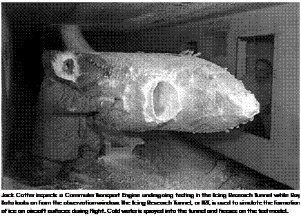
The Icing Branch has a continuing, multidisciplinary research effort aimed at the development of design and analysis tools to aid aircraft manufacturers, subsystem manufacturers, certification authorities, the military, and other Government agencies in assessing the behavior of aircraft systems in an icing environment. These tools consist of com­putational and experimental simulation methods that are validated, robust, and well documented. In addition, these tools are supported through the creation of extensive databases used for validation, cor­relation, and similitude. Current software offerings include LEWICE, LEWICE 3D, and SmaggIce. LEWICE 3D is computationally fast and can handle large problems on workstations and personal computers. It is a diverse, inexpensive tool for use in determining the icing charac­teristics of arbitrary aircraft surfaces. The code can interface with most
3-D flow solvers and can generate solutions on workstations and per­sonal computers for most cases in less than several hours.[1263]

Подпись: 12SmaggIce is short for Surface Modeling and Grid Generation for Iced Airfoils. It is a software toolkit used in the process of predicting the aerodynamic performance ice-covered airfoils using grid-based Computational Fluid Dynamics (CFD). It includes tools for data prob­ing, boundary smoothing, domain decomposition, and structured grid generation and refinement. SmaggIce provides the underlying compu­tations to perform these functions, a GUI (Graphical User Interface) to control and interact with those functions, and graphical displays of results. Until 3-D ice geometry acquisition and numerical flow sim­ulation become easier and faster for studying the effects of icing on wing performance, a 2-D CFD analysis will have to play an important role in complementing flight and wind tunnel tests and in providing insights to effects of ice on airfoil aerodynamics. Even 2-D CFD analy­sis, however, can take a lot of work using the currently available general – purpose grid-generation tools. These existing grid tools require extensive experience and effort on the part of the engineer to generate appropriate grids for moderately complex ice. In addition, these general – purpose tools do not meet unique requirements of icing effects study: ice shape characterization, geometry data evaluation and modification, and grid quality control for various ice shapes. So, SmaggIce is a 2-D software toolkit under development at GRC. It is designed to stream­line the entire 2-D icing aerodynamic analysis process from geometry preparation to grid generation to flow simulation, and to provide unique tools that are required for icing effects study.[1264]

The New Breed

Подпись: 13The intense U. S. research and development programs on high-angle – of-attack technology of the 1970s and 1980s ushered in a new era of carefree maneuvering for tactical aircraft. New options for close-in combat were now available to military pilots, and more importantly, departure/spin accidents were dramatically reduced. Design tools had been sharpened, and the widespread introduction of sophisticated dig­ital flight control systems finally permitted the implementation of auto­matic departure and spin prevention systems. These advances did not go unnoticed by foreign designers, and emerging threat aircraft were rapidly developed and exhibited with comparable high-angle-of-attack capabilities.[1321] As the Air Force and Navy prepared for the next genera­tion of fighters to replace the F-15 and F-14, the integration of superior maneuverability at high angles of attack and other performance – and signature-related capabilities became the new challenge.

HUMAN FACTORS

Human factors played a part in some of the key issues that have already been discussed above. Examples are: confidence in lift-fans, concern for approach to the fan-stall boundary, high pilot workload tasks, and conversion controller design.

The human factor issue that concerned the writer the most was that of the cockpit arrangement. An XV-5A and its pilot were probably lost because of the inadvertent actuation of an incorrectly specified and improperly positioned conversion switch. This tragic lesson must not be repeated, and care­ful human factor studies must be included in the design of modern lift-fan aircraft such as the SSTOVLF. Human fac­tor considerations should be incorporated early in the design and development of the SSTOVLF from the first simulation effort on through the introduction of the production aircraft. It is therefore the writer’s hope that SSTOVLF designers will remember the past as they design for the future and take heed of the "Lessons learned.”

Fatal Accident #1

One of the two XV-5As being flown at Edwards AFB during an official flight demonstration on the morning of April 27, 1965, crashed onto the lakebed, killing Ryan’s Chief Engineering Test Pilot, Lou Everett. The two aircraft were simultaneously dem­onstrating the high-and low-speed capabilities of the Vertifan.

During a high-speed pass, Everett’s aircraft pushed over into a 30° dive and never recovered. The accident board concluded that the uncontrolled dive was the result of an accidental actu­ation of the conversion switch that took place when the air­craft’s speed was far in excess of the safe jet-mode to fan-mode conversion speed limit. The conversion switch (a simple 2- position toggle switch) was, at the time, (improperly) located on the collective for pilot "convenience.” It was speculated that the pilot inadvertently hit the conversion switch during the high-speed pass which initiated the conversion sequence: 15° of nose-down stabilizer movement was accompanied by actuation of the diverter valves to the fan-mode. The resulting stabilizer pitching moment created an uncontrollable nose – down flight path. (Note: Mr. Everett initiated a low altitude (rocket) ejection, but tragically, the ejection seat was improp­erly rigged…another lesson learned!) As a result of this acci­dent, the conversion switch was changed to a lift-lock toggle and relocated on the main instrument panel ahead of the col­lective lever control.

Spacecraft and Electrodynamic Effects

With advent of piloted orbital flight, NASA anticipated the potential effects of lightning upon launch vehicles in the Mercury, Gemini, and Apollo programs. Sitting atop immense boosters, the spacecraft were especially vulnerable on their launch pads and in the liftoff phase. One NASA lecturer warned his audience in 1965 that explosive squibs, deto­nators, vapors, and dust were particularly vulnerable to static electrical detonation; the amount of energy required to initiate detonation was "very small,” and, as a consequence, their triggering was "considerably more frequent than is generally recognized.”[146]

As mentioned briefly, on November 14, 1969, at 11:22 a. m. EST, Apollo 12, crewed by astronauts Charles "Pete” Conrad, Richard F. Gordon, and Alan L. Bean, thundered aloft from Launch Complex 39A at the Kennedy Space Center. Launched amid a torrential downpour, it disappeared from sight almost immediately, swallowed up amid dark, foreboding clouds that cloaked even its immense flaring exhaust. The rain clouds produced an electrical field, prompting a dual trigger response initiated by the craft. As historian Roger Bilstein wrote subsequently:

Within seconds, spectators on the ground were startled to see parallel streaks of lightning flash out of the cloud back to the launch pad. Inside the spacecraft, Conrad exclaimed "I don’t know what happened here. We had everything in the world drop out.” Astronautics Pete Conrad, Richard Gordon, and Alan Bean, inside the spacecraft, had seen a brilliant flash of light inside the spacecraft, and instantaneously, red and yellow warn­ing lights all over the command module panels lit up like an electronic Christmas tree. Fuel cells stopped working, circuits went dead, and the electrically oper­ated gyroscopic platform went tumbling out of control.

The spacecraft and rocket had experienced a massive power failure. Fortunately, the emergency lasted only seconds, as backup power systems took over and the instrument unit of the Saturn V launch vehicle kept the rocket operating.[147]

The electrical disturbance triggered the loss of nine solid-state instrumentation sensors, none of which, fortunately, was essential to the safety or completion of the flight. It resulted in the temporary loss of communications, varying between 30 seconds and 3 minutes, depending upon the particular system. Rapid engagement of backup systems permitted the mission to continue, though three fuel cells were automatically (and, as subsequently proved, unnecessarily) shut down. Afterward, NASA incident investigators concluded that though lightning could be triggered by the long combined length of the Saturn V rocket and its associated exhaust plume, "The pos­sibility that the Apollo vehicle might trigger lightning had not been considered previously.”[148]

Apollo 12 constituted a dramatic wake-up call on the hazards of mixing large rockets and lightning. Afterward, the Agency devoted extensive efforts to assessing the nature of the lightning risk and seeking ways to mitigate it. The first fruit of this detailed study effort was the issuance, in August 1970, of revised electrodynamic design criteria for spacecraft. It stipulated various means of spacecraft and launch facility protection, including

1. Ensuring that all metallic sections are connected electrically (bonded) so that the current flow from a lightning stroke is conducted over the skin with­out any caps where sparking would occur or current would be carried inside.

2. Protecting objects on the ground, such as buildings, by a system of lightning rods and wires over the out­side to carry the lightning stroke to the ground.

3. Providing a cone of protection for the lightning pro­tection plan for Saturn Launch Complex 39.

4. Providing protection devices in critical circuits.

5. Using systems that have no single failure mode; i. e., the Saturn V launch vehicle uses triple-redundant circuitry on the auto-abort system, which requires two out of three of the signals to be correct before abort is initiated.

6. Appropriate shielding of units sensitive to electro­magnetic radiation.[149]

Spacecraft and Electrodynamic Effects

A 1 973 NASA projection of likely paths taken by lightning striking a composite structure Space Shuttle, showing attachment and exit points. NASA.

The stakes involved in lightning protection increased greatly with the advent of the Space Shuttle program. Officially named the Space Transportation System (STS), NASA’s Space Shuttle was envisioned as a routine space logistical support vehicle and was touted by some as a "space age DC-3,” a reference to the legendary Douglas airliner that had galvanized air transport on a global scale. Large, complex, and expen­sive, it required careful planning to avoid lightning damage, particu­larly surface burnthroughs that could constitute a flight hazard (as, alas, the loss of Columbia would tragically demonstrate three decades sub­sequently). NASA predicated its studies on Shuttle lightning vulnera­bilities on two major strokes, one having a peak current of 200 kA at a current rate of change of 100 kA per microsecond (100 kA / 10-6 sec), and a second of 100 kA at a current rate of change of 50 kA / 10-6 sec. Agency researchers also modeled various intermediate currents of lower energies. Analysis indicated that the Shuttle and its launch stack (con­sisting of the orbiter, mounted on a liquid fuel tank flanked by two solid – fuel boosters) would most likely have lightning entry points at the tip of its tankage and boosters, the leading edges of its wings at mid-span

and at the wingtip, on its upper nose surface, and (least likely) above the cockpit. Likely exit points were the nozzles of the two solid-fuel boosters, the trailing-edge tip of the vertical fin, the trailing edge of the body flap, the trailing edges of the wing tip, and (least likely) the nozzles of its three liquid-fuel Space Shuttle main engines (SSMEs).[150] Because the Shuttle orbiter was, effectively, a large delta aircraft, data and criteria assembled previously for conventional aircraft furnished a good reference base for Shuttle lightning prediction studies, even studies dating to the early 1940s. As well, Agency researchers undertook extensive tests to guard against inadvertent triggering of the Shuttle’s solid rocket boosters (SRBs), because their premature ignition would be catastrophic.[151]

Prudently, NASA ensured that the servicing structure on the Shuttle launch complex received an 80-foot lightning mast plus safety wires to guide strikes to the ground rather than through the launch vehicle. Dramatic proof of the system’s effectiveness occurred in August 1983, when lightning struck the launch pad of the Shuttle Challenger before launching mission STS-8, commanded by Richard

H. Truly. It was the first Shuttle night launch, and it subsequently pro­ceeded as planned.

The hazards of what lightning could do to a flight control system (FCS) was dramatically illustrated March 26, 1987, when a bolt led to the loss of AC-67, an Atlas-Centaur mission carrying FLTSATCOM 6, a TRW, Inc., communications satellite developed for the Navy’s Fleet Satellite Communications system. Approximately 48 seconds after launch, a cloud-to-ground lightning strike generated a spurious signal into the Centaur launch vehicle’s digital flight control computer, which then sent a hard-over engine command. The resultant abrupt yaw overstressed the vehicle, causing its virtual immediate breakup. Coming after the weather-related loss of the Space Shuttle Challenger the previous year, the loss of AC-67 was particularly disturbing. In both cases, accident investigators found that the two Kennedy teams had not taken adequate account of meteorological conditions at the time of launch.[152]

The accident led to NASA establishing a Lightning Advisory Panel to provide parameters for determining whether a launch should proceed in the presence of electrical activity. As well, it understandably stimu­lated continuing research on the electrodynamic environment at the Kennedy Space Center and on vulnerabilities of launch vehicles and facilities at the launch site. Vulnerability surveys extended to in-flight hardware, launch and ground support equipment, and ultimately almost any facility in areas of thunderstorm activity. Specific items identified as most vulnerable to lightning strikes were electronic systems, wiring and cables, and critical structures. The engineering challenge was to design methods of protecting those areas and systems without adversely affecting structural integrity or equipment performance.

To improve the fidelity of existing launch models and develop a better understanding of electrodynamic conditions around the Kennedy Center, between September 14 and November 4, 1988, NASA flew a modified single-seat single-engine Schweizer powered sailplane, the Special Purpose Test Vehicle (SPTVAR), on 20 missions over the spaceport and its reservation, measuring electrical fields. These tri­als took place in consultation with the Air Force (Detachment 11 of its 4th Weather Wing had responsibility for Cape lightning forecasting) and the New Mexico Institute of Mining and Technology, which selected candidate cloud forms for study and then monitored the real­time acquisition of field data. Flights ranged from 5,000 to 17,000 feet, averaged over an hour in duration, and took off from late morning to as late as 8 p. m. The SPTVAR aircraft dodged around electrified clouds as high as 35,000 feet, while taking measurements of electrical fields, the net airplane charge, atmospheric liquid water content, ice parti­cle concentrations, sky brightness, accelerations, air temperature and pressure, and basic aircraft parameters, such as heading, roll and pitch angles, and spatial position.[153]

After the Challenger and AC-67 launch accidents, the ongoing Shuttle program remained a particular subject of Agency concern, particularly the danger of lightning currents striking the Shuttle during rollout, on the pad, or upon liftoff. As verified by the SPTVAR survey, large currents (greater than 100 kA) were extremely rare in the operating area. Researchers con­cluded that worst-case figures for an on-pad strike ran from 0.0026 to 0.11953 percent. Trends evident in the data showed that specific operating procedures could further reduce the likelihood of a lightning strike. For instance, a study of all lightning probabilities at Kennedy Space Center observed, "If the Shuttle rollout did not occur during the evening hours, but during the peak July afternoon hours, the resultant nominal probabili­ties for a >220 kA and >50 kA lightning strike are 0.04% and 0.21%, respec­tively. Thus, it does matter ‘when’ the Shuttle is rolled out.”[154] Although estimates for a triggered strike of a Shuttle in ascent were not precisely determined, researchers concluded that the likelihood of triggered strike (one caused by the moving vehicle itself) of any magnitude on an ascend­ing launch vehicle is 140,000 times likelier than a direct hit on the pad. Because Cape Canaveral constitutes America’s premier space launch cen­ter, continued interest in lightning at the Cape and its potential impact upon launch vehicles and facilities will remain major NASA concerns.

Aviation Safety Program

After the in-flight explosion and crash of TWA 800 in July 1996, President Bill Clinton established a Commission on Aviation Safety and Security, chaired by Vice President Al Gore. The Commission’s emphasis was to find ways to reduce the number of fatal air-related accidents. Ultimately, the Commission challenged the aviation community to lower the fatal aircraft accident rate by 80 percent in 10 years and 90 percent in 25 years.

NASA’s response to this challenge was to create in 1997 the Aviation Safety Program (AvSP) and, as seen before, partner with the FAA and the DOD to conduct research on a number of fronts.[226]

NASA’s AvSP was set up with three primary objectives: (1) eliminate accidents during targeted phases of flight, (2) increase the chances that passengers would survive an accident, and (3) beef up the foundation upon which aviation safety technologies are based. From those objec­tives, NASA established six research areas, some having to do directly with making safer skyways and others pointed at increasing aircraft safety and reliability. All produced results, as noted in the referenced technical papers. Those research areas included accident mitigation,[227] systemwide accident prevention,[228] single aircraft accident prevention,[229] weather accident prevention,[230] synthetic vision,[231] and aviation system modeling and monitoring.[232]

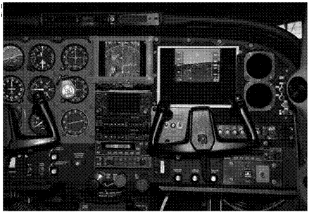
Of particular note is a trio of contributions that have lasting influence today. They include the introduction and incorporation of the glass cock­pit into the pilot’s work environment and a pair of programs to gather key data that can be processed into useful, safety enhancing information.